

This chapter is about animation and artificial intelligence (AI).
Animation is what we need in order to see things move in a game. AI is what is required for characters (other than the player) to know how to behave and react while you are in the game.
We will cover the following topics in this chapter:
Animation is the simulation of movement through a series of images or frames.
Before computers came into the picture, animation was created using traditional techniques such as hand-drawn animation and stop-motion animation (or model animation). Hand-drawn animation, as the name suggests, involves hand-drawn scenes on paper. Each scene is repeated on the next sheet of paper with a slight change in the scene. All the papers are put together in sequence and the pages are turned very quickly, like a flipbook. The slight changes on the sheets of paper create 2D animation, and this can be filmed into a motion film. This technique is used very often in Disney cartoons and movies. As you can imagine, this is a very time-consuming way to produce animation, as you would need thousands of drawings to create seconds of the film.
Stop-motion animation involves creating models, moving them a little in each frame to mimic movement, and filming this sequence to construct an entire scene. The tedious process of capturing countless snippets has limited the use of this method in favor of more mainstream animation techniques today.
Computer animation is quite similar to stop-motion animation as computer graphics is moved a little in each frame; these frames are then rendered on screen. For computer games, we use computer animation by creating 3D models using tools, such as Maya and 3ds Max. Then, we animate these models to simulate life-like behavior and actions for the game. Animation is needed for all things in order to make them move. Characters need to be animated so that they can look real—they can be in an idle position, walk, run, or execute any other action that needs to be performed in the course of the game.
Motion capture is also another very popular way to animate characters these days. This technology basically uses recorded human actions to create the computer graphic character's behavior. If you have watched the movie Avatar, the blue avatar characters were, in fact, played by human actors and then enhanced to look the way they did using computer graphics. For the filming of the movie, they advanced the motion capture technology into what is now called performance capture. This advancement in technology has empowered film and game makers to capture the details in animation in such a way that can make a CG character stand out.
Although the objective of this book is not to teach you how to animate a model, it is important to understand how animation is done so that you can understand better how to get game characters in a game to move and behave according to design.
As mentioned earlier, we can animate 3D models using tools, such as Maya or 3ds Max. We can then record their changes and then render these animations on screen when needed.
In game development, the creation of animation falls under the responsibility of an animator. Before an animation can be first created, we need to first have a 3D model that's been created by a 3D modeler. The 3D modeler is responsible for giving the object its shape and texturing it. Depending on the type of object we're dealing with, the exact process to get an object properly rigged can be slightly different. Rigging needs to be done before handing over the object to the animator to create specific animations. Sometimes, animators also need to fine-tune the rigs for better control of the animation.
Rigging is a process where a skeleton is placed in the mesh and joints that are created for the skeleton. The collection of bones/joints is known as the rig. The rig provides control points, which the animator can use to move the object in order to create the desired animation. I will use a human character model in my explanation here so that you can understand this concept easily.
The 3D or character modeler first shows how the face and body of a model are shaped. It then determines how tall the model is, creates all the required features by adding primitives to the model, and then textures it to give color to its eyes, hair, and so on. The model is now ready but still jelly on the inside because we have not given it any internal structure. Rigging is the process where we add bones to the body to hold it up. The arm can be rotated because we have given it a shoulder bone (scapula), arm bone (humerus), and a joint that can mimic the ball and socket joint. The joint we have in place for rigging is made up of a group of constraints that limit movement in various planes and angles. Hierarchies are also applied to the bone structure to help the bones link each other. The fingers are linked to the hand, which is linked to the arm. Such a relationship can be put in place so that movement looks real when one of parts moves and the rest of the parts naturally move together as well.
Tools, such as Maya and 3ds Max, provide some simplification to the rigging process, as you can use standard rigs as the base, and tweak this base according to the needs of the model. Some models are taller and require longer bones. A 3D model must have a simple skeletal structure that adheres closely to the shape and size of a 3D model. Similar sized 3D models can share the same skeletal structure.
To better understand how we can add animation to our game levels, let's learn how computer animation is created and how we can make these models move.
Animation basically mimics how life moves in the real world. Many companies go to great lengths to make computer animation as accurate as possible through the use of motion capture. They film actual movements in real life and then recreate these movements using computer 3D models.
When creating animations, the animator makes use of the bones and joints created during the rigging process and adjusts them in place using as much detail as possible to mimic their natural movement. The joints and bones work together to affect the body posture. These movements are then recorded as short animation clips known as an animation sequence. Animation sequences form the most basic blocks of animation, and they can be played once or repeatedly to create an action. For example, a walking animation is only 1.8 seconds long but can be replayed over and over to simulate walking. When this sequence is repeated again, it is commonly known as an animation loop.
Animation sequences can also be linked to form a chain of actions. While transitioning from one sequence to another, some blending might be needed in order for the movement to look natural.
Preparing before animation
In game development, the creation of animation falls under the responsibility of an animator. Before an animation can be first created, we need to first have a 3D model that's been created by a 3D modeler. The 3D modeler is responsible for giving the object its shape and texturing it. Depending on the type of object we're dealing with, the exact process to get an object properly rigged can be slightly different. Rigging needs to be done before handing over the object to the animator to create specific animations. Sometimes, animators also need to fine-tune the rigs for better control of the animation.
Rigging is a process where a skeleton is placed in the mesh and joints that are created for the skeleton. The collection of bones/joints is known as the rig. The rig provides control points, which the animator can use to move the object in order to create the desired animation. I will use a human character model in my explanation here so that you can understand this concept easily.
The 3D or character modeler first shows how the face and body of a model are shaped. It then determines how tall the model is, creates all the required features by adding primitives to the model, and then textures it to give color to its eyes, hair, and so on. The model is now ready but still jelly on the inside because we have not given it any internal structure. Rigging is the process where we add bones to the body to hold it up. The arm can be rotated because we have given it a shoulder bone (scapula), arm bone (humerus), and a joint that can mimic the ball and socket joint. The joint we have in place for rigging is made up of a group of constraints that limit movement in various planes and angles. Hierarchies are also applied to the bone structure to help the bones link each other. The fingers are linked to the hand, which is linked to the arm. Such a relationship can be put in place so that movement looks real when one of parts moves and the rest of the parts naturally move together as well.
Tools, such as Maya and 3ds Max, provide some simplification to the rigging process, as you can use standard rigs as the base, and tweak this base according to the needs of the model. Some models are taller and require longer bones. A 3D model must have a simple skeletal structure that adheres closely to the shape and size of a 3D model. Similar sized 3D models can share the same skeletal structure.
To better understand how we can add animation to our game levels, let's learn how computer animation is created and how we can make these models move.
Animation basically mimics how life moves in the real world. Many companies go to great lengths to make computer animation as accurate as possible through the use of motion capture. They film actual movements in real life and then recreate these movements using computer 3D models.
When creating animations, the animator makes use of the bones and joints created during the rigging process and adjusts them in place using as much detail as possible to mimic their natural movement. The joints and bones work together to affect the body posture. These movements are then recorded as short animation clips known as an animation sequence. Animation sequences form the most basic blocks of animation, and they can be played once or repeatedly to create an action. For example, a walking animation is only 1.8 seconds long but can be replayed over and over to simulate walking. When this sequence is repeated again, it is commonly known as an animation loop.
Animation sequences can also be linked to form a chain of actions. While transitioning from one sequence to another, some blending might be needed in order for the movement to look natural.
How is animation created?
Animation basically mimics how life moves in the real world. Many companies go to great lengths to make computer animation as accurate as possible through the use of motion capture. They film actual movements in real life and then recreate these movements using computer 3D models.
When creating animations, the animator makes use of the bones and joints created during the rigging process and adjusts them in place using as much detail as possible to mimic their natural movement. The joints and bones work together to affect the body posture. These movements are then recorded as short animation clips known as an animation sequence. Animation sequences form the most basic blocks of animation, and they can be played once or repeatedly to create an action. For example, a walking animation is only 1.8 seconds long but can be replayed over and over to simulate walking. When this sequence is repeated again, it is commonly known as an animation loop.
Animation sequences can also be linked to form a chain of actions. While transitioning from one sequence to another, some blending might be needed in order for the movement to look natural.
Animation in Unreal Engine 4 is mostly done in the Persona editor. This editor offers four different modes: Skeleton, Mesh, Animation, and Graph. These modes mainly exist so that you can jump straight into one of them to edit/create the animations more effectively. So, they are simply a loose group of functions that can be used to control the different aspects of animation. We will learn how to make use of the functions in Persona to add animation to our level.
To help improve team collaboration, Unreal Engine 4 also released a previously in-house-only toolset, which is a plugin for Maya (compatible for Maya 2013 and higher versions), known as Animation and Rigging Toolset (ART). This toolset provides a user interface to allow the creation of a skeleton, placement of the skeleton, and rig creation within Maya itself. We will not go into the details of this toolset, but you can find more information on this in Unreal's online documentation at https://docs.unrealengine.com/latest/INT/Engine/Content/Tools/MayaRiggingTool/index.html.
As many artists use Maya and 3ds Max to create 3D models and animation, Unreal Engine 4 has a great FBX Import pipeline that allows you to successfully import skeletal models, animation sequences, and morph targets. This makes it easy to transfer assets to the Unreal Editor and put them into the game. Unreal also tries to stabilize the import of art assets from other software, such as Blender and MODO.
Since 3D models and animation are first created outside Unreal Engine, for the purpose of learning about how animation works, we will import an animation pack that contains a 3D model with a number of animation sequences first, and we'll then learn how to make use of the different tools in the Unreal Editor for animation.
Unreal Engine offers a number of downloadable packs in Marketplace. Marketplace is in the start menu screen, which is under the Launch button. The following screenshot shows the startup screen that has the Marketplace tab selected for the downloadable packs. Search for Animation Starter Pack in Marketplace under Characters and Animations. This particular pack is free to download. Click on Animation Started Pack to download it.

After the pack is downloaded, you will find the pack added to the Library. The following screenshot shows where Animator Starter Pack is found in Library under Vault:

Now that we have the Animation Starter Pack in our Library, we can add it to our current project and start playing with the animations.
Click on Add To Project and a pop-up screen with all the current projects that are present in Unreal Engine will appear. Select the name of the project that you have been creating for all the various levels and all the tutorial examples. If you have followed the same project and level naming convention as me, it will be MyProject. I have also opened Chapter4Level from the previous chapter and renamed it Chapter5Level. The following screenshot shows AnimStarterPack loaded in the project:

Persona gives game developers the ability to playback and preview animation sequences, combine animation sequences into a single animation by blending, creating montages, editing skeletons/sockets, and controlling animation with Blueprints. I hope you still remember what you have learned about Blueprints in Chapter 3, Game Object – More and Move.
After adding the free animation pack into your project in the previous exercise, it is time to add some animation to the level. First of all, open Chapter4Level, rename it Chapter5Level, and then navigate to the AnimStarterPack folder using Content Browser. Go to the Character subfolder and click and drag HeroTPP into the level.
This screenshot shows how HeroTPP is added to the level:

The HeroTPP looks fake and frozen, right? Now, let's give him a better pose. Click on HeroTPP to display the details. Go to the Animation tab under Details and input the Animation Mode settings. Use Animation Asset, navigate and click on Jog_Fwd_Rifle in AnimStarterPack (in Content Browser), and then click on the arrow next to Anim to Play.

Here is a zoomed-in view of the Animation settings:

Now, build and play the level. You will see the character that you have just added to the level, is jogging.
This is the straightforward way to animate a character. However, the character continues to loop through this animation no matter what is happening around. We probably want the character to be able to react to the environment and conditions of the game. So, how can we do this?
In the previous exercise, we learned how to make a skeletal mesh take on a single animation. But can we make the skeletal mesh start running in a straight line? The next few sections of animation exercises will explain how we can do this and, subsequently, add more to this basic animation.
First of all, you need to remember that animation sequences/poses are played when you tell them to. While animating character, you need to look into the details so that the character looks normal.
Now, let's quickly recap what we did in the previous exercise: the skeletal mesh character was a zombie with no animation attached. When we linked the run animation and set it to play, the character immediately seemed like it was running. So, if we want the character to stop running, we can remove the run animation. The character goes back to looking like a zombie that hasn't been animated. If we did this in a game, you would probably think that there is something very wrong with the animation. Zombie->Running->Zombie. Nothing realistic about it.
How can we improve this? We start with an idle pose for the character; an idle pose is one where the character stands at a fixed spot and breathes. Breathing is part of animation too. It makes the character look like it's alive. Next, we set it to play the run animation. To stop this animation, we allow the character to take the idle position again. Not a bad attempt for this iteration. The character doesn't look like a zombie now, but it looks and feels real.
What else can we do to make this even better? Let's use an analogy of someone driving a car normally (not a race car driver). When moving from the start position, you accelerate from a speed of 0 up to a comfortable cruising speed. When you want to stop, you reduce the cruising speed by stepping on the brakes and then gradually go back to 0 (to avoid a stopping suddenly and giving your passengers the unpleasant experience of being thrown forward). Similarly, we can use this to help us design our character's transition from a stationary position. We will use a tool called Blend Animation to create this transition so that we can make the movement of the character a little more realistic.
Blend Animation, as the name suggests, blends various types of animation using variables. It can be a simple one-dimensional relationship where we use speed as an axis to blend the animations or a two-dimensional relationship where we use both speed and direction to blend animations. Unreal Engine's Blend Animation tool is capable of setting up the blending of animations in different ways.
In this example, we will use speed as the parameter to blend the animation. Let's quickly cover the thought process here first before listing the steps to follow in the Unreal Editor to achieve this. This would help in your understanding of how this process works instead of simply following the process to make something happen.
At speed = 0, we assign the idle pose. As the speed increases, we should switch the animation from an idle to a walking animation. As the speed increases even more, the animation switches from walking to jogging, and then running. Here's an illustration of how the blend would look:

Next, let's identify which animation sequences we have in the animation pack and would be suitable for each of the stages:
- Idle_Rifle_Hip
- Walk_Fwd_Rifle_Ironsights
- Jog_Fwd_Rifle
- Sprint_Fwd_Rifle
To create a simple 1D Blend Space, we can right-click on the Character folder, and go to Create Asset | Animation | Blend Space 1D. Alternatively, you can select the Character folder in Content Browser, click on the Create button at the top, go to Animation, and then Blend Space 1D.

Select HeroTPP_Skeleton; clicking on this creates a new Blend Space 1D. Rename newblendspace1d to WalkJogRun. Double-click on the newly created WalkJogRun to open the editor. This will propel you straight to the Animation tab of the editor. Notice that this part is highlighted in the following screenshot. In the SkeletonMesh field, we have HeroTPP_Skeleton, which was what we selected when creating the blend space earlier.

In the Animation editor, you have access to Asset Browser (which is, by default, in the bottom right-hand side of the screen). Clicking on the animation assets will allow you to preview how the animation looks.
Let's first set the X Axis Label to Speed. X Axis Range is from 0 to 375. Leave X Axis Divisions as 4.
The number of divisions creates segments in the speed graph that we have. Based on what we selected earlier for the Idle, Walk, Jog, and Run states, find the animation using Asset Browser, click and drop the animation into the WalkJogRun tab into the appropriate sections, as shown in the following screenshot:
Idle_Rifle_Hip is at speed = 0. Set Walk_Fwd_Rifle_Ironsights in the first division line. When you drag an animation into the graph, it creates a node and snaps at one of the division lines. Set Jog_Fwd_Rifle in the second division line and set Sprint_Fwd_Rifle at speed = 375. To preview how the animation blends, move the mouse over the graph along the vertical axis.

Now we have created a Blend Animation that uses speed as a parameter. How do we make an NPC change speed and then link this animation to it so that as the speed changes and the animation that is played also changes?
For a simple implementation of getting the speed and animation to change, we will set up the Animation Blueprint. Go to Content Browser. Navigate to Animation | Character; then, navigate and click on Create Asset | Animation | Animation Blueprint:

Upon selecting Animation Blueprint, the editor will prompt you about the base class that you want the Animation Blueprint to be created in. This screenshot shows the options that are available for selection:

In this example, we will pick the most basic generic class, AnimInstance, to build our Animation Blueprint in. Select HeroTPP_Skeleton as the target skeletal mesh for this blueprint. Name this Animation Blueprint MyNPC_Blueprint.
To check whether you have selected the correct target skeletal mesh, look in the Skeleton tab in the Blueprint window, as shown in the following screenshot. You should see HeroTPP_Skeleton in the box. The screenshot also shows the Graph tab that's been selected with the empty default AnimGraph showing. We will proceed through this exercise with the Graph tab selected, unless specified otherwise.
This screenshot shows the default blank AnimGraph. Final Animation Pose will receive the output of the skeletal mesh that's been specified:

First, we want to add a state machine by right-clicking within the AnimGraph and navigating to State Machines | Add New State Machine…, as shown in the following screenshot:

Rename the newly created state machine Movement:

Double-click on Movement. Create a new state named WalkJogRun:

Double-click on the newly created WalkJogRun state to modify the state in a new tab. Go to the Asset Browser tab, look for WalkJogRun blendspace, which we created in the previous exercise, and click and drag it into the editor. Link WalkJogRun blendspace to the final animation, as shown in the following screenshot. Notice that speed = 0.00 is specified in the blendspace node; this was the variable that we defined to control the change of the animation when we created blendspace in the earlier exercise.
Next, we need to create a variable so that we can pass in a value to the WalkJogRun blendspace speed variable. To do so, we need to click and drag the green dot next to the Speed on the blendspace node to open up a contextual menu, look for Promote to Variable, and then click on it. This promotes speed in the blendspace node to a float variable, which we would set to control the speed and type of animation that will be played. Rename this new variable Speed. The following screenshot shows how we have created and connected a Speed variable to WalkJogRun blendspace, which is linked to Final Animation Pose:

Now, go back to link Movement to Final Animation Pose:

Now, the entire AnimGraph is linked up. Click on Compile, and you would see the preview of the character model updated, as shown in the following screenshot. The white moving dots show how data flows through the system. The speed is 0 here.

We can also use this tab to see live preview as we change the value to Speed. The following screenshot shows you when speed is 50. The character model assumes a walking pose.

Through AnimGraph, we were able to set up Speed as a variable and link this variable to WalkJogRun blendspace, which, in turn, controls what animation to play at which speed. We need to now think about how to provide some logic to determine how the speed of the NPC changes.
EventGraph is used to program logic into the Blueprint.
In this example, we will use EventGraph to create logic to change the speed values that will, in turn, affect the NPC's animation control.
To create a more complex intelligent decision-making process, which is termed as AI, we will need to use a set of AI-related nodes in EventGraph. We will learn more about creating AI in the next section.
The following screenshot shows the default new EventGraph tab in the Animation Blueprint.
The Event Blueprint Update Animation node can be thought of as the source that sends a pulse through the EventGraph network. As this pulse travels through the network, it goes through a series of questions that you design to determine which animation is played.

Try Get Pawn Owner is to get the owner that Animation Blueprint is assigned to. This is simply used in combination with another node, IsValid, to ensure that we have a valid owner before setting values to change the animation.
To make MyNPC_Blueprint work for the Hero_TPP mesh that we have in the level, we will need to first delete the Try Get Pawn Owner node and replace it with Get Owning Component. Right-click on the EventGraph and type Get. In the contextual menu that is opened, scroll down to find Get Owning Component. This screenshot shows where the Get Owning Component node is:

In the same way, right-click in the editor and type IsValid to look for the node. This screenshot shows where to get the IsValid node:

Now, link the triangular output from Event Blueprint Update Animation to the Exec input of the IsValid node (which is also a triangular input). Link Return Value (this has a blue circle next to it) output from Get Owning Component to Input Object (this has a blue circle next to it) of the IsValid node. The following screenshot shows the linkage of the three nodes.
The explanation for this is that at every tick, we need to check whether the target skeleton mesh is valid.
For now, let's simply set the speed of the NPC to 100 if the target skeleton mesh is valid. So, right-click on the EventGraph area, and type SetSpeed to filter the options. Click and select Set Speed, as shown in this screenshot:

Link the Is Valid output of the IsValid node to the input (this has a triangular symbol) of the SET Speed node. Then, click on the box next to Speed and type 100 to set the speed:

Save and recompile now to see how the preview model changes. The following screenshot shows the model playing the walk animation when speed is set to 100:

Now, Animation Blueprint is ready for use in the game level. We need to assign this Animation Blueprint to a character in the game. Save and close the Animation Blueprint editor to go back to the main editor.
To assign the Blueprint to the skeleton mesh, we will click on the existing HeroTPP to display the details panel. Focus on the animation part of the panel; the following screenshot shows the original setting that I have when there is no animation sequence linked to the skeleton mesh and it does not use an Animation Blueprint. Set Animation Mode to Use Animation Asset and Anim to Play to None:

To use MyNPC_Blueprint for this skeleton mesh, set Animation Mode to Use Animation Blueprint. Select MyNPC_Blueprint for Anim Blueprint Generated Class:

Now, compile and run the game; you would see the NPC walking on the same spot with the speed set as 100.
Importing animation from Maya/3ds Max
As many artists use Maya and 3ds Max to create 3D models and animation, Unreal Engine 4 has a great FBX Import pipeline that allows you to successfully import skeletal models, animation sequences, and morph targets. This makes it easy to transfer assets to the Unreal Editor and put them into the game. Unreal also tries to stabilize the import of art assets from other software, such as Blender and MODO.
Since 3D models and animation are first created outside Unreal Engine, for the purpose of learning about how animation works, we will import an animation pack that contains a 3D model with a number of animation sequences first, and we'll then learn how to make use of the different tools in the Unreal Editor for animation.
Unreal Engine offers a number of downloadable packs in Marketplace. Marketplace is in the start menu screen, which is under the Launch button. The following screenshot shows the startup screen that has the Marketplace tab selected for the downloadable packs. Search for Animation Starter Pack in Marketplace under Characters and Animations. This particular pack is free to download. Click on Animation Started Pack to download it.
After the pack is downloaded, you will find the pack added to the Library. The following screenshot shows where Animator Starter Pack is found in Library under Vault:
Now that we have the Animation Starter Pack in our Library, we can add it to our current project and start playing with the animations.
Click on Add To Project and a pop-up screen with all the current projects that are present in Unreal Engine will appear. Select the name of the project that you have been creating for all the various levels and all the tutorial examples. If you have followed the same project and level naming convention as me, it will be MyProject. I have also opened Chapter4Level from the previous chapter and renamed it Chapter5Level. The following screenshot shows AnimStarterPack loaded in the project:
Persona gives game developers the ability to playback and preview animation sequences, combine animation sequences into a single animation by blending, creating montages, editing skeletons/sockets, and controlling animation with Blueprints. I hope you still remember what you have learned about Blueprints in Chapter 3, Game Object – More and Move.
After adding the free animation pack into your project in the previous exercise, it is time to add some animation to the level. First of all, open Chapter4Level, rename it Chapter5Level, and then navigate to the AnimStarterPack folder using Content Browser. Go to the Character subfolder and click and drag HeroTPP into the level.
This screenshot shows how HeroTPP is added to the level:
The HeroTPP looks fake and frozen, right? Now, let's give him a better pose. Click on HeroTPP to display the details. Go to the Animation tab under Details and input the Animation Mode settings. Use Animation Asset, navigate and click on Jog_Fwd_Rifle in AnimStarterPack (in Content Browser), and then click on the arrow next to Anim to Play.
Here is a zoomed-in view of the Animation settings:
Now, build and play the level. You will see the character that you have just added to the level, is jogging.
This is the straightforward way to animate a character. However, the character continues to loop through this animation no matter what is happening around. We probably want the character to be able to react to the environment and conditions of the game. So, how can we do this?
In the previous exercise, we learned how to make a skeletal mesh take on a single animation. But can we make the skeletal mesh start running in a straight line? The next few sections of animation exercises will explain how we can do this and, subsequently, add more to this basic animation.
First of all, you need to remember that animation sequences/poses are played when you tell them to. While animating character, you need to look into the details so that the character looks normal.
Now, let's quickly recap what we did in the previous exercise: the skeletal mesh character was a zombie with no animation attached. When we linked the run animation and set it to play, the character immediately seemed like it was running. So, if we want the character to stop running, we can remove the run animation. The character goes back to looking like a zombie that hasn't been animated. If we did this in a game, you would probably think that there is something very wrong with the animation. Zombie->Running->Zombie. Nothing realistic about it.
How can we improve this? We start with an idle pose for the character; an idle pose is one where the character stands at a fixed spot and breathes. Breathing is part of animation too. It makes the character look like it's alive. Next, we set it to play the run animation. To stop this animation, we allow the character to take the idle position again. Not a bad attempt for this iteration. The character doesn't look like a zombie now, but it looks and feels real.
What else can we do to make this even better? Let's use an analogy of someone driving a car normally (not a race car driver). When moving from the start position, you accelerate from a speed of 0 up to a comfortable cruising speed. When you want to stop, you reduce the cruising speed by stepping on the brakes and then gradually go back to 0 (to avoid a stopping suddenly and giving your passengers the unpleasant experience of being thrown forward). Similarly, we can use this to help us design our character's transition from a stationary position. We will use a tool called Blend Animation to create this transition so that we can make the movement of the character a little more realistic.
Blend Animation, as the name suggests, blends various types of animation using variables. It can be a simple one-dimensional relationship where we use speed as an axis to blend the animations or a two-dimensional relationship where we use both speed and direction to blend animations. Unreal Engine's Blend Animation tool is capable of setting up the blending of animations in different ways.
In this example, we will use speed as the parameter to blend the animation. Let's quickly cover the thought process here first before listing the steps to follow in the Unreal Editor to achieve this. This would help in your understanding of how this process works instead of simply following the process to make something happen.
At speed = 0, we assign the idle pose. As the speed increases, we should switch the animation from an idle to a walking animation. As the speed increases even more, the animation switches from walking to jogging, and then running. Here's an illustration of how the blend would look:
Next, let's identify which animation sequences we have in the animation pack and would be suitable for each of the stages:
- Idle_Rifle_Hip
- Walk_Fwd_Rifle_Ironsights
- Jog_Fwd_Rifle
- Sprint_Fwd_Rifle
To create a simple 1D Blend Space, we can right-click on the Character folder, and go to Create Asset | Animation | Blend Space 1D. Alternatively, you can select the Character folder in Content Browser, click on the Create button at the top, go to Animation, and then Blend Space 1D.
Select HeroTPP_Skeleton; clicking on this creates a new Blend Space 1D. Rename newblendspace1d to WalkJogRun. Double-click on the newly created WalkJogRun to open the editor. This will propel you straight to the Animation tab of the editor. Notice that this part is highlighted in the following screenshot. In the SkeletonMesh field, we have HeroTPP_Skeleton, which was what we selected when creating the blend space earlier.
In the Animation editor, you have access to Asset Browser (which is, by default, in the bottom right-hand side of the screen). Clicking on the animation assets will allow you to preview how the animation looks.
Let's first set the X Axis Label to Speed. X Axis Range is from 0 to 375. Leave X Axis Divisions as 4.
The number of divisions creates segments in the speed graph that we have. Based on what we selected earlier for the Idle, Walk, Jog, and Run states, find the animation using Asset Browser, click and drop the animation into the WalkJogRun tab into the appropriate sections, as shown in the following screenshot:
Idle_Rifle_Hip is at speed = 0. Set Walk_Fwd_Rifle_Ironsights in the first division line. When you drag an animation into the graph, it creates a node and snaps at one of the division lines. Set Jog_Fwd_Rifle in the second division line and set Sprint_Fwd_Rifle at speed = 375. To preview how the animation blends, move the mouse over the graph along the vertical axis.
Now we have created a Blend Animation that uses speed as a parameter. How do we make an NPC change speed and then link this animation to it so that as the speed changes and the animation that is played also changes?
For a simple implementation of getting the speed and animation to change, we will set up the Animation Blueprint. Go to Content Browser. Navigate to Animation | Character; then, navigate and click on Create Asset | Animation | Animation Blueprint:
Upon selecting Animation Blueprint, the editor will prompt you about the base class that you want the Animation Blueprint to be created in. This screenshot shows the options that are available for selection:
In this example, we will pick the most basic generic class, AnimInstance, to build our Animation Blueprint in. Select HeroTPP_Skeleton as the target skeletal mesh for this blueprint. Name this Animation Blueprint MyNPC_Blueprint.
To check whether you have selected the correct target skeletal mesh, look in the Skeleton tab in the Blueprint window, as shown in the following screenshot. You should see HeroTPP_Skeleton in the box. The screenshot also shows the Graph tab that's been selected with the empty default AnimGraph showing. We will proceed through this exercise with the Graph tab selected, unless specified otherwise.
This screenshot shows the default blank AnimGraph. Final Animation Pose will receive the output of the skeletal mesh that's been specified:
First, we want to add a state machine by right-clicking within the AnimGraph and navigating to State Machines | Add New State Machine…, as shown in the following screenshot:
Rename the newly created state machine Movement:
Double-click on Movement. Create a new state named WalkJogRun:
Double-click on the newly created WalkJogRun state to modify the state in a new tab. Go to the Asset Browser tab, look for WalkJogRun blendspace, which we created in the previous exercise, and click and drag it into the editor. Link WalkJogRun blendspace to the final animation, as shown in the following screenshot. Notice that speed = 0.00 is specified in the blendspace node; this was the variable that we defined to control the change of the animation when we created blendspace in the earlier exercise.
Next, we need to create a variable so that we can pass in a value to the WalkJogRun blendspace speed variable. To do so, we need to click and drag the green dot next to the Speed on the blendspace node to open up a contextual menu, look for Promote to Variable, and then click on it. This promotes speed in the blendspace node to a float variable, which we would set to control the speed and type of animation that will be played. Rename this new variable Speed. The following screenshot shows how we have created and connected a Speed variable to WalkJogRun blendspace, which is linked to Final Animation Pose:
Now, go back to link Movement to Final Animation Pose:
Now, the entire AnimGraph is linked up. Click on Compile, and you would see the preview of the character model updated, as shown in the following screenshot. The white moving dots show how data flows through the system. The speed is 0 here.
We can also use this tab to see live preview as we change the value to Speed. The following screenshot shows you when speed is 50. The character model assumes a walking pose.
Through AnimGraph, we were able to set up Speed as a variable and link this variable to WalkJogRun blendspace, which, in turn, controls what animation to play at which speed. We need to now think about how to provide some logic to determine how the speed of the NPC changes.
EventGraph is used to program logic into the Blueprint.
In this example, we will use EventGraph to create logic to change the speed values that will, in turn, affect the NPC's animation control.
To create a more complex intelligent decision-making process, which is termed as AI, we will need to use a set of AI-related nodes in EventGraph. We will learn more about creating AI in the next section.
The following screenshot shows the default new EventGraph tab in the Animation Blueprint.
The Event Blueprint Update Animation node can be thought of as the source that sends a pulse through the EventGraph network. As this pulse travels through the network, it goes through a series of questions that you design to determine which animation is played.
Try Get Pawn Owner is to get the owner that Animation Blueprint is assigned to. This is simply used in combination with another node, IsValid, to ensure that we have a valid owner before setting values to change the animation.
To make MyNPC_Blueprint work for the Hero_TPP mesh that we have in the level, we will need to first delete the Try Get Pawn Owner node and replace it with Get Owning Component. Right-click on the EventGraph and type Get. In the contextual menu that is opened, scroll down to find Get Owning Component. This screenshot shows where the Get Owning Component node is:
In the same way, right-click in the editor and type IsValid to look for the node. This screenshot shows where to get the IsValid node:
Now, link the triangular output from Event Blueprint Update Animation to the Exec input of the IsValid node (which is also a triangular input). Link Return Value (this has a blue circle next to it) output from Get Owning Component to Input Object (this has a blue circle next to it) of the IsValid node. The following screenshot shows the linkage of the three nodes.
The explanation for this is that at every tick, we need to check whether the target skeleton mesh is valid.
For now, let's simply set the speed of the NPC to 100 if the target skeleton mesh is valid. So, right-click on the EventGraph area, and type SetSpeed to filter the options. Click and select Set Speed, as shown in this screenshot:
Link the Is Valid output of the IsValid node to the input (this has a triangular symbol) of the SET Speed node. Then, click on the box next to Speed and type 100 to set the speed:
Save and recompile now to see how the preview model changes. The following screenshot shows the model playing the walk animation when speed is set to 100:
Now, Animation Blueprint is ready for use in the game level. We need to assign this Animation Blueprint to a character in the game. Save and close the Animation Blueprint editor to go back to the main editor.
To assign the Blueprint to the skeleton mesh, we will click on the existing HeroTPP to display the details panel. Focus on the animation part of the panel; the following screenshot shows the original setting that I have when there is no animation sequence linked to the skeleton mesh and it does not use an Animation Blueprint. Set Animation Mode to Use Animation Asset and Anim to Play to None:
To use MyNPC_Blueprint for this skeleton mesh, set Animation Mode to Use Animation Blueprint. Select MyNPC_Blueprint for Anim Blueprint Generated Class:
Now, compile and run the game; you would see the NPC walking on the same spot with the speed set as 100.
Tutorial – importing the animation pack from Marketplace
Since 3D models and animation are first created outside Unreal Engine, for the purpose of learning about how animation works, we will import an animation pack that contains a 3D model with a number of animation sequences first, and we'll then learn how to make use of the different tools in the Unreal Editor for animation.
Unreal Engine offers a number of downloadable packs in Marketplace. Marketplace is in the start menu screen, which is under the Launch button. The following screenshot shows the startup screen that has the Marketplace tab selected for the downloadable packs. Search for Animation Starter Pack in Marketplace under Characters and Animations. This particular pack is free to download. Click on Animation Started Pack to download it.
After the pack is downloaded, you will find the pack added to the Library. The following screenshot shows where Animator Starter Pack is found in Library under Vault:
Now that we have the Animation Starter Pack in our Library, we can add it to our current project and start playing with the animations.
Click on Add To Project and a pop-up screen with all the current projects that are present in Unreal Engine will appear. Select the name of the project that you have been creating for all the various levels and all the tutorial examples. If you have followed the same project and level naming convention as me, it will be MyProject. I have also opened Chapter4Level from the previous chapter and renamed it Chapter5Level. The following screenshot shows AnimStarterPack loaded in the project:
Persona gives game developers the ability to playback and preview animation sequences, combine animation sequences into a single animation by blending, creating montages, editing skeletons/sockets, and controlling animation with Blueprints. I hope you still remember what you have learned about Blueprints in Chapter 3, Game Object – More and Move.
After adding the free animation pack into your project in the previous exercise, it is time to add some animation to the level. First of all, open Chapter4Level, rename it Chapter5Level, and then navigate to the AnimStarterPack folder using Content Browser. Go to the Character subfolder and click and drag HeroTPP into the level.
This screenshot shows how HeroTPP is added to the level:
The HeroTPP looks fake and frozen, right? Now, let's give him a better pose. Click on HeroTPP to display the details. Go to the Animation tab under Details and input the Animation Mode settings. Use Animation Asset, navigate and click on Jog_Fwd_Rifle in AnimStarterPack (in Content Browser), and then click on the arrow next to Anim to Play.
Here is a zoomed-in view of the Animation settings:
Now, build and play the level. You will see the character that you have just added to the level, is jogging.
This is the straightforward way to animate a character. However, the character continues to loop through this animation no matter what is happening around. We probably want the character to be able to react to the environment and conditions of the game. So, how can we do this?
In the previous exercise, we learned how to make a skeletal mesh take on a single animation. But can we make the skeletal mesh start running in a straight line? The next few sections of animation exercises will explain how we can do this and, subsequently, add more to this basic animation.
First of all, you need to remember that animation sequences/poses are played when you tell them to. While animating character, you need to look into the details so that the character looks normal.
Now, let's quickly recap what we did in the previous exercise: the skeletal mesh character was a zombie with no animation attached. When we linked the run animation and set it to play, the character immediately seemed like it was running. So, if we want the character to stop running, we can remove the run animation. The character goes back to looking like a zombie that hasn't been animated. If we did this in a game, you would probably think that there is something very wrong with the animation. Zombie->Running->Zombie. Nothing realistic about it.
How can we improve this? We start with an idle pose for the character; an idle pose is one where the character stands at a fixed spot and breathes. Breathing is part of animation too. It makes the character look like it's alive. Next, we set it to play the run animation. To stop this animation, we allow the character to take the idle position again. Not a bad attempt for this iteration. The character doesn't look like a zombie now, but it looks and feels real.
What else can we do to make this even better? Let's use an analogy of someone driving a car normally (not a race car driver). When moving from the start position, you accelerate from a speed of 0 up to a comfortable cruising speed. When you want to stop, you reduce the cruising speed by stepping on the brakes and then gradually go back to 0 (to avoid a stopping suddenly and giving your passengers the unpleasant experience of being thrown forward). Similarly, we can use this to help us design our character's transition from a stationary position. We will use a tool called Blend Animation to create this transition so that we can make the movement of the character a little more realistic.
Blend Animation, as the name suggests, blends various types of animation using variables. It can be a simple one-dimensional relationship where we use speed as an axis to blend the animations or a two-dimensional relationship where we use both speed and direction to blend animations. Unreal Engine's Blend Animation tool is capable of setting up the blending of animations in different ways.
In this example, we will use speed as the parameter to blend the animation. Let's quickly cover the thought process here first before listing the steps to follow in the Unreal Editor to achieve this. This would help in your understanding of how this process works instead of simply following the process to make something happen.
At speed = 0, we assign the idle pose. As the speed increases, we should switch the animation from an idle to a walking animation. As the speed increases even more, the animation switches from walking to jogging, and then running. Here's an illustration of how the blend would look:
Next, let's identify which animation sequences we have in the animation pack and would be suitable for each of the stages:
- Idle_Rifle_Hip
- Walk_Fwd_Rifle_Ironsights
- Jog_Fwd_Rifle
- Sprint_Fwd_Rifle
To create a simple 1D Blend Space, we can right-click on the Character folder, and go to Create Asset | Animation | Blend Space 1D. Alternatively, you can select the Character folder in Content Browser, click on the Create button at the top, go to Animation, and then Blend Space 1D.
Select HeroTPP_Skeleton; clicking on this creates a new Blend Space 1D. Rename newblendspace1d to WalkJogRun. Double-click on the newly created WalkJogRun to open the editor. This will propel you straight to the Animation tab of the editor. Notice that this part is highlighted in the following screenshot. In the SkeletonMesh field, we have HeroTPP_Skeleton, which was what we selected when creating the blend space earlier.
In the Animation editor, you have access to Asset Browser (which is, by default, in the bottom right-hand side of the screen). Clicking on the animation assets will allow you to preview how the animation looks.
Let's first set the X Axis Label to Speed. X Axis Range is from 0 to 375. Leave X Axis Divisions as 4.
The number of divisions creates segments in the speed graph that we have. Based on what we selected earlier for the Idle, Walk, Jog, and Run states, find the animation using Asset Browser, click and drop the animation into the WalkJogRun tab into the appropriate sections, as shown in the following screenshot:
Idle_Rifle_Hip is at speed = 0. Set Walk_Fwd_Rifle_Ironsights in the first division line. When you drag an animation into the graph, it creates a node and snaps at one of the division lines. Set Jog_Fwd_Rifle in the second division line and set Sprint_Fwd_Rifle at speed = 375. To preview how the animation blends, move the mouse over the graph along the vertical axis.
Now we have created a Blend Animation that uses speed as a parameter. How do we make an NPC change speed and then link this animation to it so that as the speed changes and the animation that is played also changes?
For a simple implementation of getting the speed and animation to change, we will set up the Animation Blueprint. Go to Content Browser. Navigate to Animation | Character; then, navigate and click on Create Asset | Animation | Animation Blueprint:
Upon selecting Animation Blueprint, the editor will prompt you about the base class that you want the Animation Blueprint to be created in. This screenshot shows the options that are available for selection:
In this example, we will pick the most basic generic class, AnimInstance, to build our Animation Blueprint in. Select HeroTPP_Skeleton as the target skeletal mesh for this blueprint. Name this Animation Blueprint MyNPC_Blueprint.
To check whether you have selected the correct target skeletal mesh, look in the Skeleton tab in the Blueprint window, as shown in the following screenshot. You should see HeroTPP_Skeleton in the box. The screenshot also shows the Graph tab that's been selected with the empty default AnimGraph showing. We will proceed through this exercise with the Graph tab selected, unless specified otherwise.
This screenshot shows the default blank AnimGraph. Final Animation Pose will receive the output of the skeletal mesh that's been specified:
First, we want to add a state machine by right-clicking within the AnimGraph and navigating to State Machines | Add New State Machine…, as shown in the following screenshot:
Rename the newly created state machine Movement:
Double-click on Movement. Create a new state named WalkJogRun:
Double-click on the newly created WalkJogRun state to modify the state in a new tab. Go to the Asset Browser tab, look for WalkJogRun blendspace, which we created in the previous exercise, and click and drag it into the editor. Link WalkJogRun blendspace to the final animation, as shown in the following screenshot. Notice that speed = 0.00 is specified in the blendspace node; this was the variable that we defined to control the change of the animation when we created blendspace in the earlier exercise.
Next, we need to create a variable so that we can pass in a value to the WalkJogRun blendspace speed variable. To do so, we need to click and drag the green dot next to the Speed on the blendspace node to open up a contextual menu, look for Promote to Variable, and then click on it. This promotes speed in the blendspace node to a float variable, which we would set to control the speed and type of animation that will be played. Rename this new variable Speed. The following screenshot shows how we have created and connected a Speed variable to WalkJogRun blendspace, which is linked to Final Animation Pose:
Now, go back to link Movement to Final Animation Pose:
Now, the entire AnimGraph is linked up. Click on Compile, and you would see the preview of the character model updated, as shown in the following screenshot. The white moving dots show how data flows through the system. The speed is 0 here.
We can also use this tab to see live preview as we change the value to Speed. The following screenshot shows you when speed is 50. The character model assumes a walking pose.
Through AnimGraph, we were able to set up Speed as a variable and link this variable to WalkJogRun blendspace, which, in turn, controls what animation to play at which speed. We need to now think about how to provide some logic to determine how the speed of the NPC changes.
EventGraph is used to program logic into the Blueprint.
In this example, we will use EventGraph to create logic to change the speed values that will, in turn, affect the NPC's animation control.
To create a more complex intelligent decision-making process, which is termed as AI, we will need to use a set of AI-related nodes in EventGraph. We will learn more about creating AI in the next section.
The following screenshot shows the default new EventGraph tab in the Animation Blueprint.
The Event Blueprint Update Animation node can be thought of as the source that sends a pulse through the EventGraph network. As this pulse travels through the network, it goes through a series of questions that you design to determine which animation is played.
Try Get Pawn Owner is to get the owner that Animation Blueprint is assigned to. This is simply used in combination with another node, IsValid, to ensure that we have a valid owner before setting values to change the animation.
To make MyNPC_Blueprint work for the Hero_TPP mesh that we have in the level, we will need to first delete the Try Get Pawn Owner node and replace it with Get Owning Component. Right-click on the EventGraph and type Get. In the contextual menu that is opened, scroll down to find Get Owning Component. This screenshot shows where the Get Owning Component node is:
In the same way, right-click in the editor and type IsValid to look for the node. This screenshot shows where to get the IsValid node:
Now, link the triangular output from Event Blueprint Update Animation to the Exec input of the IsValid node (which is also a triangular input). Link Return Value (this has a blue circle next to it) output from Get Owning Component to Input Object (this has a blue circle next to it) of the IsValid node. The following screenshot shows the linkage of the three nodes.
The explanation for this is that at every tick, we need to check whether the target skeleton mesh is valid.
For now, let's simply set the speed of the NPC to 100 if the target skeleton mesh is valid. So, right-click on the EventGraph area, and type SetSpeed to filter the options. Click and select Set Speed, as shown in this screenshot:
Link the Is Valid output of the IsValid node to the input (this has a triangular symbol) of the SET Speed node. Then, click on the box next to Speed and type 100 to set the speed:
Save and recompile now to see how the preview model changes. The following screenshot shows the model playing the walk animation when speed is set to 100:
Now, Animation Blueprint is ready for use in the game level. We need to assign this Animation Blueprint to a character in the game. Save and close the Animation Blueprint editor to go back to the main editor.
To assign the Blueprint to the skeleton mesh, we will click on the existing HeroTPP to display the details panel. Focus on the animation part of the panel; the following screenshot shows the original setting that I have when there is no animation sequence linked to the skeleton mesh and it does not use an Animation Blueprint. Set Animation Mode to Use Animation Asset and Anim to Play to None:
To use MyNPC_Blueprint for this skeleton mesh, set Animation Mode to Use Animation Blueprint. Select MyNPC_Blueprint for Anim Blueprint Generated Class:
Now, compile and run the game; you would see the NPC walking on the same spot with the speed set as 100.
What can you do with Persona?
Persona gives game developers the ability to playback and preview animation sequences, combine animation sequences into a single animation by blending, creating montages, editing skeletons/sockets, and controlling animation with Blueprints. I hope you still remember what you have learned about Blueprints in Chapter 3, Game Object – More and Move.
After adding the free animation pack into your project in the previous exercise, it is time to add some animation to the level. First of all, open Chapter4Level, rename it Chapter5Level, and then navigate to the AnimStarterPack folder using Content Browser. Go to the Character subfolder and click and drag HeroTPP into the level.
This screenshot shows how HeroTPP is added to the level:
The HeroTPP looks fake and frozen, right? Now, let's give him a better pose. Click on HeroTPP to display the details. Go to the Animation tab under Details and input the Animation Mode settings. Use Animation Asset, navigate and click on Jog_Fwd_Rifle in AnimStarterPack (in Content Browser), and then click on the arrow next to Anim to Play.
Here is a zoomed-in view of the Animation settings:
Now, build and play the level. You will see the character that you have just added to the level, is jogging.
This is the straightforward way to animate a character. However, the character continues to loop through this animation no matter what is happening around. We probably want the character to be able to react to the environment and conditions of the game. So, how can we do this?
In the previous exercise, we learned how to make a skeletal mesh take on a single animation. But can we make the skeletal mesh start running in a straight line? The next few sections of animation exercises will explain how we can do this and, subsequently, add more to this basic animation.
First of all, you need to remember that animation sequences/poses are played when you tell them to. While animating character, you need to look into the details so that the character looks normal.
Now, let's quickly recap what we did in the previous exercise: the skeletal mesh character was a zombie with no animation attached. When we linked the run animation and set it to play, the character immediately seemed like it was running. So, if we want the character to stop running, we can remove the run animation. The character goes back to looking like a zombie that hasn't been animated. If we did this in a game, you would probably think that there is something very wrong with the animation. Zombie->Running->Zombie. Nothing realistic about it.
How can we improve this? We start with an idle pose for the character; an idle pose is one where the character stands at a fixed spot and breathes. Breathing is part of animation too. It makes the character look like it's alive. Next, we set it to play the run animation. To stop this animation, we allow the character to take the idle position again. Not a bad attempt for this iteration. The character doesn't look like a zombie now, but it looks and feels real.
What else can we do to make this even better? Let's use an analogy of someone driving a car normally (not a race car driver). When moving from the start position, you accelerate from a speed of 0 up to a comfortable cruising speed. When you want to stop, you reduce the cruising speed by stepping on the brakes and then gradually go back to 0 (to avoid a stopping suddenly and giving your passengers the unpleasant experience of being thrown forward). Similarly, we can use this to help us design our character's transition from a stationary position. We will use a tool called Blend Animation to create this transition so that we can make the movement of the character a little more realistic.
Blend Animation, as the name suggests, blends various types of animation using variables. It can be a simple one-dimensional relationship where we use speed as an axis to blend the animations or a two-dimensional relationship where we use both speed and direction to blend animations. Unreal Engine's Blend Animation tool is capable of setting up the blending of animations in different ways.
In this example, we will use speed as the parameter to blend the animation. Let's quickly cover the thought process here first before listing the steps to follow in the Unreal Editor to achieve this. This would help in your understanding of how this process works instead of simply following the process to make something happen.
At speed = 0, we assign the idle pose. As the speed increases, we should switch the animation from an idle to a walking animation. As the speed increases even more, the animation switches from walking to jogging, and then running. Here's an illustration of how the blend would look:
Next, let's identify which animation sequences we have in the animation pack and would be suitable for each of the stages:
- Idle_Rifle_Hip
- Walk_Fwd_Rifle_Ironsights
- Jog_Fwd_Rifle
- Sprint_Fwd_Rifle
To create a simple 1D Blend Space, we can right-click on the Character folder, and go to Create Asset | Animation | Blend Space 1D. Alternatively, you can select the Character folder in Content Browser, click on the Create button at the top, go to Animation, and then Blend Space 1D.
Select HeroTPP_Skeleton; clicking on this creates a new Blend Space 1D. Rename newblendspace1d to WalkJogRun. Double-click on the newly created WalkJogRun to open the editor. This will propel you straight to the Animation tab of the editor. Notice that this part is highlighted in the following screenshot. In the SkeletonMesh field, we have HeroTPP_Skeleton, which was what we selected when creating the blend space earlier.
In the Animation editor, you have access to Asset Browser (which is, by default, in the bottom right-hand side of the screen). Clicking on the animation assets will allow you to preview how the animation looks.
Let's first set the X Axis Label to Speed. X Axis Range is from 0 to 375. Leave X Axis Divisions as 4.
The number of divisions creates segments in the speed graph that we have. Based on what we selected earlier for the Idle, Walk, Jog, and Run states, find the animation using Asset Browser, click and drop the animation into the WalkJogRun tab into the appropriate sections, as shown in the following screenshot:
Idle_Rifle_Hip is at speed = 0. Set Walk_Fwd_Rifle_Ironsights in the first division line. When you drag an animation into the graph, it creates a node and snaps at one of the division lines. Set Jog_Fwd_Rifle in the second division line and set Sprint_Fwd_Rifle at speed = 375. To preview how the animation blends, move the mouse over the graph along the vertical axis.
Now we have created a Blend Animation that uses speed as a parameter. How do we make an NPC change speed and then link this animation to it so that as the speed changes and the animation that is played also changes?
For a simple implementation of getting the speed and animation to change, we will set up the Animation Blueprint. Go to Content Browser. Navigate to Animation | Character; then, navigate and click on Create Asset | Animation | Animation Blueprint:
Upon selecting Animation Blueprint, the editor will prompt you about the base class that you want the Animation Blueprint to be created in. This screenshot shows the options that are available for selection:
In this example, we will pick the most basic generic class, AnimInstance, to build our Animation Blueprint in. Select HeroTPP_Skeleton as the target skeletal mesh for this blueprint. Name this Animation Blueprint MyNPC_Blueprint.
To check whether you have selected the correct target skeletal mesh, look in the Skeleton tab in the Blueprint window, as shown in the following screenshot. You should see HeroTPP_Skeleton in the box. The screenshot also shows the Graph tab that's been selected with the empty default AnimGraph showing. We will proceed through this exercise with the Graph tab selected, unless specified otherwise.
This screenshot shows the default blank AnimGraph. Final Animation Pose will receive the output of the skeletal mesh that's been specified:
First, we want to add a state machine by right-clicking within the AnimGraph and navigating to State Machines | Add New State Machine…, as shown in the following screenshot:
Rename the newly created state machine Movement:
Double-click on Movement. Create a new state named WalkJogRun:
Double-click on the newly created WalkJogRun state to modify the state in a new tab. Go to the Asset Browser tab, look for WalkJogRun blendspace, which we created in the previous exercise, and click and drag it into the editor. Link WalkJogRun blendspace to the final animation, as shown in the following screenshot. Notice that speed = 0.00 is specified in the blendspace node; this was the variable that we defined to control the change of the animation when we created blendspace in the earlier exercise.
Next, we need to create a variable so that we can pass in a value to the WalkJogRun blendspace speed variable. To do so, we need to click and drag the green dot next to the Speed on the blendspace node to open up a contextual menu, look for Promote to Variable, and then click on it. This promotes speed in the blendspace node to a float variable, which we would set to control the speed and type of animation that will be played. Rename this new variable Speed. The following screenshot shows how we have created and connected a Speed variable to WalkJogRun blendspace, which is linked to Final Animation Pose:
Now, go back to link Movement to Final Animation Pose:
Now, the entire AnimGraph is linked up. Click on Compile, and you would see the preview of the character model updated, as shown in the following screenshot. The white moving dots show how data flows through the system. The speed is 0 here.
We can also use this tab to see live preview as we change the value to Speed. The following screenshot shows you when speed is 50. The character model assumes a walking pose.
Through AnimGraph, we were able to set up Speed as a variable and link this variable to WalkJogRun blendspace, which, in turn, controls what animation to play at which speed. We need to now think about how to provide some logic to determine how the speed of the NPC changes.
EventGraph is used to program logic into the Blueprint.
In this example, we will use EventGraph to create logic to change the speed values that will, in turn, affect the NPC's animation control.
To create a more complex intelligent decision-making process, which is termed as AI, we will need to use a set of AI-related nodes in EventGraph. We will learn more about creating AI in the next section.
The following screenshot shows the default new EventGraph tab in the Animation Blueprint.
The Event Blueprint Update Animation node can be thought of as the source that sends a pulse through the EventGraph network. As this pulse travels through the network, it goes through a series of questions that you design to determine which animation is played.
Try Get Pawn Owner is to get the owner that Animation Blueprint is assigned to. This is simply used in combination with another node, IsValid, to ensure that we have a valid owner before setting values to change the animation.
To make MyNPC_Blueprint work for the Hero_TPP mesh that we have in the level, we will need to first delete the Try Get Pawn Owner node and replace it with Get Owning Component. Right-click on the EventGraph and type Get. In the contextual menu that is opened, scroll down to find Get Owning Component. This screenshot shows where the Get Owning Component node is:
In the same way, right-click in the editor and type IsValid to look for the node. This screenshot shows where to get the IsValid node:
Now, link the triangular output from Event Blueprint Update Animation to the Exec input of the IsValid node (which is also a triangular input). Link Return Value (this has a blue circle next to it) output from Get Owning Component to Input Object (this has a blue circle next to it) of the IsValid node. The following screenshot shows the linkage of the three nodes.
The explanation for this is that at every tick, we need to check whether the target skeleton mesh is valid.
For now, let's simply set the speed of the NPC to 100 if the target skeleton mesh is valid. So, right-click on the EventGraph area, and type SetSpeed to filter the options. Click and select Set Speed, as shown in this screenshot:
Link the Is Valid output of the IsValid node to the input (this has a triangular symbol) of the SET Speed node. Then, click on the box next to Speed and type 100 to set the speed:
Save and recompile now to see how the preview model changes. The following screenshot shows the model playing the walk animation when speed is set to 100:
Now, Animation Blueprint is ready for use in the game level. We need to assign this Animation Blueprint to a character in the game. Save and close the Animation Blueprint editor to go back to the main editor.
To assign the Blueprint to the skeleton mesh, we will click on the existing HeroTPP to display the details panel. Focus on the animation part of the panel; the following screenshot shows the original setting that I have when there is no animation sequence linked to the skeleton mesh and it does not use an Animation Blueprint. Set Animation Mode to Use Animation Asset and Anim to Play to None:
To use MyNPC_Blueprint for this skeleton mesh, set Animation Mode to Use Animation Blueprint. Select MyNPC_Blueprint for Anim Blueprint Generated Class:
Now, compile and run the game; you would see the NPC walking on the same spot with the speed set as 100.
Tutorial – assigning existing animation to a Pawn
After adding the free animation pack into your project in the previous exercise, it is time to add some animation to the level. First of all, open Chapter4Level, rename it Chapter5Level, and then navigate to the AnimStarterPack folder using Content Browser. Go to the Character subfolder and click and drag HeroTPP into the level.
This screenshot shows how HeroTPP is added to the level:
The HeroTPP looks fake and frozen, right? Now, let's give him a better pose. Click on HeroTPP to display the details. Go to the Animation tab under Details and input the Animation Mode settings. Use Animation Asset, navigate and click on Jog_Fwd_Rifle in AnimStarterPack (in Content Browser), and then click on the arrow next to Anim to Play.
Here is a zoomed-in view of the Animation settings:
Now, build and play the level. You will see the character that you have just added to the level, is jogging.
This is the straightforward way to animate a character. However, the character continues to loop through this animation no matter what is happening around. We probably want the character to be able to react to the environment and conditions of the game. So, how can we do this?
In the previous exercise, we learned how to make a skeletal mesh take on a single animation. But can we make the skeletal mesh start running in a straight line? The next few sections of animation exercises will explain how we can do this and, subsequently, add more to this basic animation.
First of all, you need to remember that animation sequences/poses are played when you tell them to. While animating character, you need to look into the details so that the character looks normal.
Now, let's quickly recap what we did in the previous exercise: the skeletal mesh character was a zombie with no animation attached. When we linked the run animation and set it to play, the character immediately seemed like it was running. So, if we want the character to stop running, we can remove the run animation. The character goes back to looking like a zombie that hasn't been animated. If we did this in a game, you would probably think that there is something very wrong with the animation. Zombie->Running->Zombie. Nothing realistic about it.
How can we improve this? We start with an idle pose for the character; an idle pose is one where the character stands at a fixed spot and breathes. Breathing is part of animation too. It makes the character look like it's alive. Next, we set it to play the run animation. To stop this animation, we allow the character to take the idle position again. Not a bad attempt for this iteration. The character doesn't look like a zombie now, but it looks and feels real.
What else can we do to make this even better? Let's use an analogy of someone driving a car normally (not a race car driver). When moving from the start position, you accelerate from a speed of 0 up to a comfortable cruising speed. When you want to stop, you reduce the cruising speed by stepping on the brakes and then gradually go back to 0 (to avoid a stopping suddenly and giving your passengers the unpleasant experience of being thrown forward). Similarly, we can use this to help us design our character's transition from a stationary position. We will use a tool called Blend Animation to create this transition so that we can make the movement of the character a little more realistic.
Blend Animation, as the name suggests, blends various types of animation using variables. It can be a simple one-dimensional relationship where we use speed as an axis to blend the animations or a two-dimensional relationship where we use both speed and direction to blend animations. Unreal Engine's Blend Animation tool is capable of setting up the blending of animations in different ways.
In this example, we will use speed as the parameter to blend the animation. Let's quickly cover the thought process here first before listing the steps to follow in the Unreal Editor to achieve this. This would help in your understanding of how this process works instead of simply following the process to make something happen.
At speed = 0, we assign the idle pose. As the speed increases, we should switch the animation from an idle to a walking animation. As the speed increases even more, the animation switches from walking to jogging, and then running. Here's an illustration of how the blend would look:
Next, let's identify which animation sequences we have in the animation pack and would be suitable for each of the stages:
- Idle_Rifle_Hip
- Walk_Fwd_Rifle_Ironsights
- Jog_Fwd_Rifle
- Sprint_Fwd_Rifle
To create a simple 1D Blend Space, we can right-click on the Character folder, and go to Create Asset | Animation | Blend Space 1D. Alternatively, you can select the Character folder in Content Browser, click on the Create button at the top, go to Animation, and then Blend Space 1D.
Select HeroTPP_Skeleton; clicking on this creates a new Blend Space 1D. Rename newblendspace1d to WalkJogRun. Double-click on the newly created WalkJogRun to open the editor. This will propel you straight to the Animation tab of the editor. Notice that this part is highlighted in the following screenshot. In the SkeletonMesh field, we have HeroTPP_Skeleton, which was what we selected when creating the blend space earlier.
In the Animation editor, you have access to Asset Browser (which is, by default, in the bottom right-hand side of the screen). Clicking on the animation assets will allow you to preview how the animation looks.
Let's first set the X Axis Label to Speed. X Axis Range is from 0 to 375. Leave X Axis Divisions as 4.
The number of divisions creates segments in the speed graph that we have. Based on what we selected earlier for the Idle, Walk, Jog, and Run states, find the animation using Asset Browser, click and drop the animation into the WalkJogRun tab into the appropriate sections, as shown in the following screenshot:
Idle_Rifle_Hip is at speed = 0. Set Walk_Fwd_Rifle_Ironsights in the first division line. When you drag an animation into the graph, it creates a node and snaps at one of the division lines. Set Jog_Fwd_Rifle in the second division line and set Sprint_Fwd_Rifle at speed = 375. To preview how the animation blends, move the mouse over the graph along the vertical axis.
Now we have created a Blend Animation that uses speed as a parameter. How do we make an NPC change speed and then link this animation to it so that as the speed changes and the animation that is played also changes?
For a simple implementation of getting the speed and animation to change, we will set up the Animation Blueprint. Go to Content Browser. Navigate to Animation | Character; then, navigate and click on Create Asset | Animation | Animation Blueprint:
Upon selecting Animation Blueprint, the editor will prompt you about the base class that you want the Animation Blueprint to be created in. This screenshot shows the options that are available for selection:
In this example, we will pick the most basic generic class, AnimInstance, to build our Animation Blueprint in. Select HeroTPP_Skeleton as the target skeletal mesh for this blueprint. Name this Animation Blueprint MyNPC_Blueprint.
To check whether you have selected the correct target skeletal mesh, look in the Skeleton tab in the Blueprint window, as shown in the following screenshot. You should see HeroTPP_Skeleton in the box. The screenshot also shows the Graph tab that's been selected with the empty default AnimGraph showing. We will proceed through this exercise with the Graph tab selected, unless specified otherwise.
This screenshot shows the default blank AnimGraph. Final Animation Pose will receive the output of the skeletal mesh that's been specified:
First, we want to add a state machine by right-clicking within the AnimGraph and navigating to State Machines | Add New State Machine…, as shown in the following screenshot:
Rename the newly created state machine Movement:
Double-click on Movement. Create a new state named WalkJogRun:
Double-click on the newly created WalkJogRun state to modify the state in a new tab. Go to the Asset Browser tab, look for WalkJogRun blendspace, which we created in the previous exercise, and click and drag it into the editor. Link WalkJogRun blendspace to the final animation, as shown in the following screenshot. Notice that speed = 0.00 is specified in the blendspace node; this was the variable that we defined to control the change of the animation when we created blendspace in the earlier exercise.
Next, we need to create a variable so that we can pass in a value to the WalkJogRun blendspace speed variable. To do so, we need to click and drag the green dot next to the Speed on the blendspace node to open up a contextual menu, look for Promote to Variable, and then click on it. This promotes speed in the blendspace node to a float variable, which we would set to control the speed and type of animation that will be played. Rename this new variable Speed. The following screenshot shows how we have created and connected a Speed variable to WalkJogRun blendspace, which is linked to Final Animation Pose:
Now, go back to link Movement to Final Animation Pose:
Now, the entire AnimGraph is linked up. Click on Compile, and you would see the preview of the character model updated, as shown in the following screenshot. The white moving dots show how data flows through the system. The speed is 0 here.
We can also use this tab to see live preview as we change the value to Speed. The following screenshot shows you when speed is 50. The character model assumes a walking pose.
Through AnimGraph, we were able to set up Speed as a variable and link this variable to WalkJogRun blendspace, which, in turn, controls what animation to play at which speed. We need to now think about how to provide some logic to determine how the speed of the NPC changes.
EventGraph is used to program logic into the Blueprint.
In this example, we will use EventGraph to create logic to change the speed values that will, in turn, affect the NPC's animation control.
To create a more complex intelligent decision-making process, which is termed as AI, we will need to use a set of AI-related nodes in EventGraph. We will learn more about creating AI in the next section.
The following screenshot shows the default new EventGraph tab in the Animation Blueprint.
The Event Blueprint Update Animation node can be thought of as the source that sends a pulse through the EventGraph network. As this pulse travels through the network, it goes through a series of questions that you design to determine which animation is played.
Try Get Pawn Owner is to get the owner that Animation Blueprint is assigned to. This is simply used in combination with another node, IsValid, to ensure that we have a valid owner before setting values to change the animation.
To make MyNPC_Blueprint work for the Hero_TPP mesh that we have in the level, we will need to first delete the Try Get Pawn Owner node and replace it with Get Owning Component. Right-click on the EventGraph and type Get. In the contextual menu that is opened, scroll down to find Get Owning Component. This screenshot shows where the Get Owning Component node is:
In the same way, right-click in the editor and type IsValid to look for the node. This screenshot shows where to get the IsValid node:
Now, link the triangular output from Event Blueprint Update Animation to the Exec input of the IsValid node (which is also a triangular input). Link Return Value (this has a blue circle next to it) output from Get Owning Component to Input Object (this has a blue circle next to it) of the IsValid node. The following screenshot shows the linkage of the three nodes.
The explanation for this is that at every tick, we need to check whether the target skeleton mesh is valid.
For now, let's simply set the speed of the NPC to 100 if the target skeleton mesh is valid. So, right-click on the EventGraph area, and type SetSpeed to filter the options. Click and select Set Speed, as shown in this screenshot:
Link the Is Valid output of the IsValid node to the input (this has a triangular symbol) of the SET Speed node. Then, click on the box next to Speed and type 100 to set the speed:
Save and recompile now to see how the preview model changes. The following screenshot shows the model playing the walk animation when speed is set to 100:
Now, Animation Blueprint is ready for use in the game level. We need to assign this Animation Blueprint to a character in the game. Save and close the Animation Blueprint editor to go back to the main editor.
To assign the Blueprint to the skeleton mesh, we will click on the existing HeroTPP to display the details panel. Focus on the animation part of the panel; the following screenshot shows the original setting that I have when there is no animation sequence linked to the skeleton mesh and it does not use an Animation Blueprint. Set Animation Mode to Use Animation Asset and Anim to Play to None:
To use MyNPC_Blueprint for this skeleton mesh, set Animation Mode to Use Animation Blueprint. Select MyNPC_Blueprint for Anim Blueprint Generated Class:
Now, compile and run the game; you would see the NPC walking on the same spot with the speed set as 100.
Why do we need to blend animations?
In the previous exercise, we learned how to make a skeletal mesh take on a single animation. But can we make the skeletal mesh start running in a straight line? The next few sections of animation exercises will explain how we can do this and, subsequently, add more to this basic animation.
First of all, you need to remember that animation sequences/poses are played when you tell them to. While animating character, you need to look into the details so that the character looks normal.
Now, let's quickly recap what we did in the previous exercise: the skeletal mesh character was a zombie with no animation attached. When we linked the run animation and set it to play, the character immediately seemed like it was running. So, if we want the character to stop running, we can remove the run animation. The character goes back to looking like a zombie that hasn't been animated. If we did this in a game, you would probably think that there is something very wrong with the animation. Zombie->Running->Zombie. Nothing realistic about it.
How can we improve this? We start with an idle pose for the character; an idle pose is one where the character stands at a fixed spot and breathes. Breathing is part of animation too. It makes the character look like it's alive. Next, we set it to play the run animation. To stop this animation, we allow the character to take the idle position again. Not a bad attempt for this iteration. The character doesn't look like a zombie now, but it looks and feels real.
What else can we do to make this even better? Let's use an analogy of someone driving a car normally (not a race car driver). When moving from the start position, you accelerate from a speed of 0 up to a comfortable cruising speed. When you want to stop, you reduce the cruising speed by stepping on the brakes and then gradually go back to 0 (to avoid a stopping suddenly and giving your passengers the unpleasant experience of being thrown forward). Similarly, we can use this to help us design our character's transition from a stationary position. We will use a tool called Blend Animation to create this transition so that we can make the movement of the character a little more realistic.
Blend Animation, as the name suggests, blends various types of animation using variables. It can be a simple one-dimensional relationship where we use speed as an axis to blend the animations or a two-dimensional relationship where we use both speed and direction to blend animations. Unreal Engine's Blend Animation tool is capable of setting up the blending of animations in different ways.
In this example, we will use speed as the parameter to blend the animation. Let's quickly cover the thought process here first before listing the steps to follow in the Unreal Editor to achieve this. This would help in your understanding of how this process works instead of simply following the process to make something happen.
At speed = 0, we assign the idle pose. As the speed increases, we should switch the animation from an idle to a walking animation. As the speed increases even more, the animation switches from walking to jogging, and then running. Here's an illustration of how the blend would look:
Next, let's identify which animation sequences we have in the animation pack and would be suitable for each of the stages:
- Idle_Rifle_Hip
- Walk_Fwd_Rifle_Ironsights
- Jog_Fwd_Rifle
- Sprint_Fwd_Rifle
To create a simple 1D Blend Space, we can right-click on the Character folder, and go to Create Asset | Animation | Blend Space 1D. Alternatively, you can select the Character folder in Content Browser, click on the Create button at the top, go to Animation, and then Blend Space 1D.
Select HeroTPP_Skeleton; clicking on this creates a new Blend Space 1D. Rename newblendspace1d to WalkJogRun. Double-click on the newly created WalkJogRun to open the editor. This will propel you straight to the Animation tab of the editor. Notice that this part is highlighted in the following screenshot. In the SkeletonMesh field, we have HeroTPP_Skeleton, which was what we selected when creating the blend space earlier.
In the Animation editor, you have access to Asset Browser (which is, by default, in the bottom right-hand side of the screen). Clicking on the animation assets will allow you to preview how the animation looks.
Let's first set the X Axis Label to Speed. X Axis Range is from 0 to 375. Leave X Axis Divisions as 4.
The number of divisions creates segments in the speed graph that we have. Based on what we selected earlier for the Idle, Walk, Jog, and Run states, find the animation using Asset Browser, click and drop the animation into the WalkJogRun tab into the appropriate sections, as shown in the following screenshot:
Idle_Rifle_Hip is at speed = 0. Set Walk_Fwd_Rifle_Ironsights in the first division line. When you drag an animation into the graph, it creates a node and snaps at one of the division lines. Set Jog_Fwd_Rifle in the second division line and set Sprint_Fwd_Rifle at speed = 375. To preview how the animation blends, move the mouse over the graph along the vertical axis.
Now we have created a Blend Animation that uses speed as a parameter. How do we make an NPC change speed and then link this animation to it so that as the speed changes and the animation that is played also changes?
For a simple implementation of getting the speed and animation to change, we will set up the Animation Blueprint. Go to Content Browser. Navigate to Animation | Character; then, navigate and click on Create Asset | Animation | Animation Blueprint:
Upon selecting Animation Blueprint, the editor will prompt you about the base class that you want the Animation Blueprint to be created in. This screenshot shows the options that are available for selection:
In this example, we will pick the most basic generic class, AnimInstance, to build our Animation Blueprint in. Select HeroTPP_Skeleton as the target skeletal mesh for this blueprint. Name this Animation Blueprint MyNPC_Blueprint.
To check whether you have selected the correct target skeletal mesh, look in the Skeleton tab in the Blueprint window, as shown in the following screenshot. You should see HeroTPP_Skeleton in the box. The screenshot also shows the Graph tab that's been selected with the empty default AnimGraph showing. We will proceed through this exercise with the Graph tab selected, unless specified otherwise.
This screenshot shows the default blank AnimGraph. Final Animation Pose will receive the output of the skeletal mesh that's been specified:
First, we want to add a state machine by right-clicking within the AnimGraph and navigating to State Machines | Add New State Machine…, as shown in the following screenshot:
Rename the newly created state machine Movement:
Double-click on Movement. Create a new state named WalkJogRun:
Double-click on the newly created WalkJogRun state to modify the state in a new tab. Go to the Asset Browser tab, look for WalkJogRun blendspace, which we created in the previous exercise, and click and drag it into the editor. Link WalkJogRun blendspace to the final animation, as shown in the following screenshot. Notice that speed = 0.00 is specified in the blendspace node; this was the variable that we defined to control the change of the animation when we created blendspace in the earlier exercise.
Next, we need to create a variable so that we can pass in a value to the WalkJogRun blendspace speed variable. To do so, we need to click and drag the green dot next to the Speed on the blendspace node to open up a contextual menu, look for Promote to Variable, and then click on it. This promotes speed in the blendspace node to a float variable, which we would set to control the speed and type of animation that will be played. Rename this new variable Speed. The following screenshot shows how we have created and connected a Speed variable to WalkJogRun blendspace, which is linked to Final Animation Pose:
Now, go back to link Movement to Final Animation Pose:
Now, the entire AnimGraph is linked up. Click on Compile, and you would see the preview of the character model updated, as shown in the following screenshot. The white moving dots show how data flows through the system. The speed is 0 here.
We can also use this tab to see live preview as we change the value to Speed. The following screenshot shows you when speed is 50. The character model assumes a walking pose.
Through AnimGraph, we were able to set up Speed as a variable and link this variable to WalkJogRun blendspace, which, in turn, controls what animation to play at which speed. We need to now think about how to provide some logic to determine how the speed of the NPC changes.
EventGraph is used to program logic into the Blueprint.
In this example, we will use EventGraph to create logic to change the speed values that will, in turn, affect the NPC's animation control.
To create a more complex intelligent decision-making process, which is termed as AI, we will need to use a set of AI-related nodes in EventGraph. We will learn more about creating AI in the next section.
The following screenshot shows the default new EventGraph tab in the Animation Blueprint.
The Event Blueprint Update Animation node can be thought of as the source that sends a pulse through the EventGraph network. As this pulse travels through the network, it goes through a series of questions that you design to determine which animation is played.
Try Get Pawn Owner is to get the owner that Animation Blueprint is assigned to. This is simply used in combination with another node, IsValid, to ensure that we have a valid owner before setting values to change the animation.
To make MyNPC_Blueprint work for the Hero_TPP mesh that we have in the level, we will need to first delete the Try Get Pawn Owner node and replace it with Get Owning Component. Right-click on the EventGraph and type Get. In the contextual menu that is opened, scroll down to find Get Owning Component. This screenshot shows where the Get Owning Component node is:
In the same way, right-click in the editor and type IsValid to look for the node. This screenshot shows where to get the IsValid node:
Now, link the triangular output from Event Blueprint Update Animation to the Exec input of the IsValid node (which is also a triangular input). Link Return Value (this has a blue circle next to it) output from Get Owning Component to Input Object (this has a blue circle next to it) of the IsValid node. The following screenshot shows the linkage of the three nodes.
The explanation for this is that at every tick, we need to check whether the target skeleton mesh is valid.
For now, let's simply set the speed of the NPC to 100 if the target skeleton mesh is valid. So, right-click on the EventGraph area, and type SetSpeed to filter the options. Click and select Set Speed, as shown in this screenshot:
Link the Is Valid output of the IsValid node to the input (this has a triangular symbol) of the SET Speed node. Then, click on the box next to Speed and type 100 to set the speed:
Save and recompile now to see how the preview model changes. The following screenshot shows the model playing the walk animation when speed is set to 100:
Now, Animation Blueprint is ready for use in the game level. We need to assign this Animation Blueprint to a character in the game. Save and close the Animation Blueprint editor to go back to the main editor.
To assign the Blueprint to the skeleton mesh, we will click on the existing HeroTPP to display the details panel. Focus on the animation part of the panel; the following screenshot shows the original setting that I have when there is no animation sequence linked to the skeleton mesh and it does not use an Animation Blueprint. Set Animation Mode to Use Animation Asset and Anim to Play to None:
To use MyNPC_Blueprint for this skeleton mesh, set Animation Mode to Use Animation Blueprint. Select MyNPC_Blueprint for Anim Blueprint Generated Class:
Now, compile and run the game; you would see the NPC walking on the same spot with the speed set as 100.
Tutorial – creating a Blend Animation
In this example, we will use speed as the parameter to blend the animation. Let's quickly cover the thought process here first before listing the steps to follow in the Unreal Editor to achieve this. This would help in your understanding of how this process works instead of simply following the process to make something happen.
At speed = 0, we assign the idle pose. As the speed increases, we should switch the animation from an idle to a walking animation. As the speed increases even more, the animation switches from walking to jogging, and then running. Here's an illustration of how the blend would look:
Next, let's identify which animation sequences we have in the animation pack and would be suitable for each of the stages:
- Idle_Rifle_Hip
- Walk_Fwd_Rifle_Ironsights
- Jog_Fwd_Rifle
- Sprint_Fwd_Rifle
To create a simple 1D Blend Space, we can right-click on the Character folder, and go to Create Asset | Animation | Blend Space 1D. Alternatively, you can select the Character folder in Content Browser, click on the Create button at the top, go to Animation, and then Blend Space 1D.
Select HeroTPP_Skeleton; clicking on this creates a new Blend Space 1D. Rename newblendspace1d to WalkJogRun. Double-click on the newly created WalkJogRun to open the editor. This will propel you straight to the Animation tab of the editor. Notice that this part is highlighted in the following screenshot. In the SkeletonMesh field, we have HeroTPP_Skeleton, which was what we selected when creating the blend space earlier.
In the Animation editor, you have access to Asset Browser (which is, by default, in the bottom right-hand side of the screen). Clicking on the animation assets will allow you to preview how the animation looks.
Let's first set the X Axis Label to Speed. X Axis Range is from 0 to 375. Leave X Axis Divisions as 4.
The number of divisions creates segments in the speed graph that we have. Based on what we selected earlier for the Idle, Walk, Jog, and Run states, find the animation using Asset Browser, click and drop the animation into the WalkJogRun tab into the appropriate sections, as shown in the following screenshot:
Idle_Rifle_Hip is at speed = 0. Set Walk_Fwd_Rifle_Ironsights in the first division line. When you drag an animation into the graph, it creates a node and snaps at one of the division lines. Set Jog_Fwd_Rifle in the second division line and set Sprint_Fwd_Rifle at speed = 375. To preview how the animation blends, move the mouse over the graph along the vertical axis.
Now we have created a Blend Animation that uses speed as a parameter. How do we make an NPC change speed and then link this animation to it so that as the speed changes and the animation that is played also changes?
For a simple implementation of getting the speed and animation to change, we will set up the Animation Blueprint. Go to Content Browser. Navigate to Animation | Character; then, navigate and click on Create Asset | Animation | Animation Blueprint:
Upon selecting Animation Blueprint, the editor will prompt you about the base class that you want the Animation Blueprint to be created in. This screenshot shows the options that are available for selection:
In this example, we will pick the most basic generic class, AnimInstance, to build our Animation Blueprint in. Select HeroTPP_Skeleton as the target skeletal mesh for this blueprint. Name this Animation Blueprint MyNPC_Blueprint.
To check whether you have selected the correct target skeletal mesh, look in the Skeleton tab in the Blueprint window, as shown in the following screenshot. You should see HeroTPP_Skeleton in the box. The screenshot also shows the Graph tab that's been selected with the empty default AnimGraph showing. We will proceed through this exercise with the Graph tab selected, unless specified otherwise.
This screenshot shows the default blank AnimGraph. Final Animation Pose will receive the output of the skeletal mesh that's been specified:
First, we want to add a state machine by right-clicking within the AnimGraph and navigating to State Machines | Add New State Machine…, as shown in the following screenshot:
Rename the newly created state machine Movement:
Double-click on Movement. Create a new state named WalkJogRun:
Double-click on the newly created WalkJogRun state to modify the state in a new tab. Go to the Asset Browser tab, look for WalkJogRun blendspace, which we created in the previous exercise, and click and drag it into the editor. Link WalkJogRun blendspace to the final animation, as shown in the following screenshot. Notice that speed = 0.00 is specified in the blendspace node; this was the variable that we defined to control the change of the animation when we created blendspace in the earlier exercise.
Next, we need to create a variable so that we can pass in a value to the WalkJogRun blendspace speed variable. To do so, we need to click and drag the green dot next to the Speed on the blendspace node to open up a contextual menu, look for Promote to Variable, and then click on it. This promotes speed in the blendspace node to a float variable, which we would set to control the speed and type of animation that will be played. Rename this new variable Speed. The following screenshot shows how we have created and connected a Speed variable to WalkJogRun blendspace, which is linked to Final Animation Pose:
Now, go back to link Movement to Final Animation Pose:
Now, the entire AnimGraph is linked up. Click on Compile, and you would see the preview of the character model updated, as shown in the following screenshot. The white moving dots show how data flows through the system. The speed is 0 here.
We can also use this tab to see live preview as we change the value to Speed. The following screenshot shows you when speed is 50. The character model assumes a walking pose.
Through AnimGraph, we were able to set up Speed as a variable and link this variable to WalkJogRun blendspace, which, in turn, controls what animation to play at which speed. We need to now think about how to provide some logic to determine how the speed of the NPC changes.
EventGraph is used to program logic into the Blueprint.
In this example, we will use EventGraph to create logic to change the speed values that will, in turn, affect the NPC's animation control.
To create a more complex intelligent decision-making process, which is termed as AI, we will need to use a set of AI-related nodes in EventGraph. We will learn more about creating AI in the next section.
The following screenshot shows the default new EventGraph tab in the Animation Blueprint.
The Event Blueprint Update Animation node can be thought of as the source that sends a pulse through the EventGraph network. As this pulse travels through the network, it goes through a series of questions that you design to determine which animation is played.
Try Get Pawn Owner is to get the owner that Animation Blueprint is assigned to. This is simply used in combination with another node, IsValid, to ensure that we have a valid owner before setting values to change the animation.
To make MyNPC_Blueprint work for the Hero_TPP mesh that we have in the level, we will need to first delete the Try Get Pawn Owner node and replace it with Get Owning Component. Right-click on the EventGraph and type Get. In the contextual menu that is opened, scroll down to find Get Owning Component. This screenshot shows where the Get Owning Component node is:
In the same way, right-click in the editor and type IsValid to look for the node. This screenshot shows where to get the IsValid node:
Now, link the triangular output from Event Blueprint Update Animation to the Exec input of the IsValid node (which is also a triangular input). Link Return Value (this has a blue circle next to it) output from Get Owning Component to Input Object (this has a blue circle next to it) of the IsValid node. The following screenshot shows the linkage of the three nodes.
The explanation for this is that at every tick, we need to check whether the target skeleton mesh is valid.
For now, let's simply set the speed of the NPC to 100 if the target skeleton mesh is valid. So, right-click on the EventGraph area, and type SetSpeed to filter the options. Click and select Set Speed, as shown in this screenshot:
Link the Is Valid output of the IsValid node to the input (this has a triangular symbol) of the SET Speed node. Then, click on the box next to Speed and type 100 to set the speed:
Save and recompile now to see how the preview model changes. The following screenshot shows the model playing the walk animation when speed is set to 100:
Now, Animation Blueprint is ready for use in the game level. We need to assign this Animation Blueprint to a character in the game. Save and close the Animation Blueprint editor to go back to the main editor.
To assign the Blueprint to the skeleton mesh, we will click on the existing HeroTPP to display the details panel. Focus on the animation part of the panel; the following screenshot shows the original setting that I have when there is no animation sequence linked to the skeleton mesh and it does not use an Animation Blueprint. Set Animation Mode to Use Animation Asset and Anim to Play to None:
To use MyNPC_Blueprint for this skeleton mesh, set Animation Mode to Use Animation Blueprint. Select MyNPC_Blueprint for Anim Blueprint Generated Class:
Now, compile and run the game; you would see the NPC walking on the same spot with the speed set as 100.
Tutorial – setting up the Animation Blueprint to use a Blend Animation
Now we have created a Blend Animation that uses speed as a parameter. How do we make an NPC change speed and then link this animation to it so that as the speed changes and the animation that is played also changes?
For a simple implementation of getting the speed and animation to change, we will set up the Animation Blueprint. Go to Content Browser. Navigate to Animation | Character; then, navigate and click on Create Asset | Animation | Animation Blueprint:
Upon selecting Animation Blueprint, the editor will prompt you about the base class that you want the Animation Blueprint to be created in. This screenshot shows the options that are available for selection:
In this example, we will pick the most basic generic class, AnimInstance, to build our Animation Blueprint in. Select HeroTPP_Skeleton as the target skeletal mesh for this blueprint. Name this Animation Blueprint MyNPC_Blueprint.
To check whether you have selected the correct target skeletal mesh, look in the Skeleton tab in the Blueprint window, as shown in the following screenshot. You should see HeroTPP_Skeleton in the box. The screenshot also shows the Graph tab that's been selected with the empty default AnimGraph showing. We will proceed through this exercise with the Graph tab selected, unless specified otherwise.
This screenshot shows the default blank AnimGraph. Final Animation Pose will receive the output of the skeletal mesh that's been specified:
First, we want to add a state machine by right-clicking within the AnimGraph and navigating to State Machines | Add New State Machine…, as shown in the following screenshot:
Rename the newly created state machine Movement:
Double-click on Movement. Create a new state named WalkJogRun:
Double-click on the newly created WalkJogRun state to modify the state in a new tab. Go to the Asset Browser tab, look for WalkJogRun blendspace, which we created in the previous exercise, and click and drag it into the editor. Link WalkJogRun blendspace to the final animation, as shown in the following screenshot. Notice that speed = 0.00 is specified in the blendspace node; this was the variable that we defined to control the change of the animation when we created blendspace in the earlier exercise.
Next, we need to create a variable so that we can pass in a value to the WalkJogRun blendspace speed variable. To do so, we need to click and drag the green dot next to the Speed on the blendspace node to open up a contextual menu, look for Promote to Variable, and then click on it. This promotes speed in the blendspace node to a float variable, which we would set to control the speed and type of animation that will be played. Rename this new variable Speed. The following screenshot shows how we have created and connected a Speed variable to WalkJogRun blendspace, which is linked to Final Animation Pose:
Now, go back to link Movement to Final Animation Pose:
Now, the entire AnimGraph is linked up. Click on Compile, and you would see the preview of the character model updated, as shown in the following screenshot. The white moving dots show how data flows through the system. The speed is 0 here.
We can also use this tab to see live preview as we change the value to Speed. The following screenshot shows you when speed is 50. The character model assumes a walking pose.
Through AnimGraph, we were able to set up Speed as a variable and link this variable to WalkJogRun blendspace, which, in turn, controls what animation to play at which speed. We need to now think about how to provide some logic to determine how the speed of the NPC changes.
EventGraph is used to program logic into the Blueprint.
In this example, we will use EventGraph to create logic to change the speed values that will, in turn, affect the NPC's animation control.
To create a more complex intelligent decision-making process, which is termed as AI, we will need to use a set of AI-related nodes in EventGraph. We will learn more about creating AI in the next section.
The following screenshot shows the default new EventGraph tab in the Animation Blueprint.
The Event Blueprint Update Animation node can be thought of as the source that sends a pulse through the EventGraph network. As this pulse travels through the network, it goes through a series of questions that you design to determine which animation is played.
Try Get Pawn Owner is to get the owner that Animation Blueprint is assigned to. This is simply used in combination with another node, IsValid, to ensure that we have a valid owner before setting values to change the animation.
To make MyNPC_Blueprint work for the Hero_TPP mesh that we have in the level, we will need to first delete the Try Get Pawn Owner node and replace it with Get Owning Component. Right-click on the EventGraph and type Get. In the contextual menu that is opened, scroll down to find Get Owning Component. This screenshot shows where the Get Owning Component node is:
In the same way, right-click in the editor and type IsValid to look for the node. This screenshot shows where to get the IsValid node:
Now, link the triangular output from Event Blueprint Update Animation to the Exec input of the IsValid node (which is also a triangular input). Link Return Value (this has a blue circle next to it) output from Get Owning Component to Input Object (this has a blue circle next to it) of the IsValid node. The following screenshot shows the linkage of the three nodes.
The explanation for this is that at every tick, we need to check whether the target skeleton mesh is valid.
For now, let's simply set the speed of the NPC to 100 if the target skeleton mesh is valid. So, right-click on the EventGraph area, and type SetSpeed to filter the options. Click and select Set Speed, as shown in this screenshot:
Link the Is Valid output of the IsValid node to the input (this has a triangular symbol) of the SET Speed node. Then, click on the box next to Speed and type 100 to set the speed:
Save and recompile now to see how the preview model changes. The following screenshot shows the model playing the walk animation when speed is set to 100:
Now, Animation Blueprint is ready for use in the game level. We need to assign this Animation Blueprint to a character in the game. Save and close the Animation Blueprint editor to go back to the main editor.
To assign the Blueprint to the skeleton mesh, we will click on the existing HeroTPP to display the details panel. Focus on the animation part of the panel; the following screenshot shows the original setting that I have when there is no animation sequence linked to the skeleton mesh and it does not use an Animation Blueprint. Set Animation Mode to Use Animation Asset and Anim to Play to None:
To use MyNPC_Blueprint for this skeleton mesh, set Animation Mode to Use Animation Blueprint. Select MyNPC_Blueprint for Anim Blueprint Generated Class:
Now, compile and run the game; you would see the NPC walking on the same spot with the speed set as 100.
AnimGraph
This screenshot shows the default blank AnimGraph. Final Animation Pose will receive the output of the skeletal mesh that's been specified:
First, we want to add a state machine by right-clicking within the AnimGraph and navigating to State Machines | Add New State Machine…, as shown in the following screenshot:
Rename the newly created state machine Movement:
Double-click on Movement. Create a new state named WalkJogRun:
Double-click on the newly created WalkJogRun state to modify the state in a new tab. Go to the Asset Browser tab, look for WalkJogRun blendspace, which we created in the previous exercise, and click and drag it into the editor. Link WalkJogRun blendspace to the final animation, as shown in the following screenshot. Notice that speed = 0.00 is specified in the blendspace node; this was the variable that we defined to control the change of the animation when we created blendspace in the earlier exercise.
Next, we need to create a variable so that we can pass in a value to the WalkJogRun blendspace speed variable. To do so, we need to click and drag the green dot next to the Speed on the blendspace node to open up a contextual menu, look for Promote to Variable, and then click on it. This promotes speed in the blendspace node to a float variable, which we would set to control the speed and type of animation that will be played. Rename this new variable Speed. The following screenshot shows how we have created and connected a Speed variable to WalkJogRun blendspace, which is linked to Final Animation Pose:
Now, go back to link Movement to Final Animation Pose:
Now, the entire AnimGraph is linked up. Click on Compile, and you would see the preview of the character model updated, as shown in the following screenshot. The white moving dots show how data flows through the system. The speed is 0 here.
We can also use this tab to see live preview as we change the value to Speed. The following screenshot shows you when speed is 50. The character model assumes a walking pose.
Through AnimGraph, we were able to set up Speed as a variable and link this variable to WalkJogRun blendspace, which, in turn, controls what animation to play at which speed. We need to now think about how to provide some logic to determine how the speed of the NPC changes.
EventGraph is used to program logic into the Blueprint.
In this example, we will use EventGraph to create logic to change the speed values that will, in turn, affect the NPC's animation control.
To create a more complex intelligent decision-making process, which is termed as AI, we will need to use a set of AI-related nodes in EventGraph. We will learn more about creating AI in the next section.
The following screenshot shows the default new EventGraph tab in the Animation Blueprint.
The Event Blueprint Update Animation node can be thought of as the source that sends a pulse through the EventGraph network. As this pulse travels through the network, it goes through a series of questions that you design to determine which animation is played.
Try Get Pawn Owner is to get the owner that Animation Blueprint is assigned to. This is simply used in combination with another node, IsValid, to ensure that we have a valid owner before setting values to change the animation.
To make MyNPC_Blueprint work for the Hero_TPP mesh that we have in the level, we will need to first delete the Try Get Pawn Owner node and replace it with Get Owning Component. Right-click on the EventGraph and type Get. In the contextual menu that is opened, scroll down to find Get Owning Component. This screenshot shows where the Get Owning Component node is:
In the same way, right-click in the editor and type IsValid to look for the node. This screenshot shows where to get the IsValid node:
Now, link the triangular output from Event Blueprint Update Animation to the Exec input of the IsValid node (which is also a triangular input). Link Return Value (this has a blue circle next to it) output from Get Owning Component to Input Object (this has a blue circle next to it) of the IsValid node. The following screenshot shows the linkage of the three nodes.
The explanation for this is that at every tick, we need to check whether the target skeleton mesh is valid.
For now, let's simply set the speed of the NPC to 100 if the target skeleton mesh is valid. So, right-click on the EventGraph area, and type SetSpeed to filter the options. Click and select Set Speed, as shown in this screenshot:
Link the Is Valid output of the IsValid node to the input (this has a triangular symbol) of the SET Speed node. Then, click on the box next to Speed and type 100 to set the speed:
Save and recompile now to see how the preview model changes. The following screenshot shows the model playing the walk animation when speed is set to 100:
Now, Animation Blueprint is ready for use in the game level. We need to assign this Animation Blueprint to a character in the game. Save and close the Animation Blueprint editor to go back to the main editor.
To assign the Blueprint to the skeleton mesh, we will click on the existing HeroTPP to display the details panel. Focus on the animation part of the panel; the following screenshot shows the original setting that I have when there is no animation sequence linked to the skeleton mesh and it does not use an Animation Blueprint. Set Animation Mode to Use Animation Asset and Anim to Play to None:
To use MyNPC_Blueprint for this skeleton mesh, set Animation Mode to Use Animation Blueprint. Select MyNPC_Blueprint for Anim Blueprint Generated Class:
Now, compile and run the game; you would see the NPC walking on the same spot with the speed set as 100.
EventGraph
EventGraph is used to program logic into the Blueprint.
In this example, we will use EventGraph to create logic to change the speed values that will, in turn, affect the NPC's animation control.
To create a more complex intelligent decision-making process, which is termed as AI, we will need to use a set of AI-related nodes in EventGraph. We will learn more about creating AI in the next section.
The following screenshot shows the default new EventGraph tab in the Animation Blueprint.
The Event Blueprint Update Animation node can be thought of as the source that sends a pulse through the EventGraph network. As this pulse travels through the network, it goes through a series of questions that you design to determine which animation is played.
Try Get Pawn Owner is to get the owner that Animation Blueprint is assigned to. This is simply used in combination with another node, IsValid, to ensure that we have a valid owner before setting values to change the animation.
To make MyNPC_Blueprint work for the Hero_TPP mesh that we have in the level, we will need to first delete the Try Get Pawn Owner node and replace it with Get Owning Component. Right-click on the EventGraph and type Get. In the contextual menu that is opened, scroll down to find Get Owning Component. This screenshot shows where the Get Owning Component node is:
In the same way, right-click in the editor and type IsValid to look for the node. This screenshot shows where to get the IsValid node:
Now, link the triangular output from Event Blueprint Update Animation to the Exec input of the IsValid node (which is also a triangular input). Link Return Value (this has a blue circle next to it) output from Get Owning Component to Input Object (this has a blue circle next to it) of the IsValid node. The following screenshot shows the linkage of the three nodes.
The explanation for this is that at every tick, we need to check whether the target skeleton mesh is valid.
For now, let's simply set the speed of the NPC to 100 if the target skeleton mesh is valid. So, right-click on the EventGraph area, and type SetSpeed to filter the options. Click and select Set Speed, as shown in this screenshot:
Link the Is Valid output of the IsValid node to the input (this has a triangular symbol) of the SET Speed node. Then, click on the box next to Speed and type 100 to set the speed:
Save and recompile now to see how the preview model changes. The following screenshot shows the model playing the walk animation when speed is set to 100:
Now, Animation Blueprint is ready for use in the game level. We need to assign this Animation Blueprint to a character in the game. Save and close the Animation Blueprint editor to go back to the main editor.
To assign the Blueprint to the skeleton mesh, we will click on the existing HeroTPP to display the details panel. Focus on the animation part of the panel; the following screenshot shows the original setting that I have when there is no animation sequence linked to the skeleton mesh and it does not use an Animation Blueprint. Set Animation Mode to Use Animation Asset and Anim to Play to None:
To use MyNPC_Blueprint for this skeleton mesh, set Animation Mode to Use Animation Blueprint. Select MyNPC_Blueprint for Anim Blueprint Generated Class:
Now, compile and run the game; you would see the NPC walking on the same spot with the speed set as 100.
AI is a decision-making process that adds NPCs in a game. AI is a programmable decision-making process for NPCs to govern their responses and behaviors in a game. A game character that is not controlled by a human player has no form of intelligence, and when these characters need to have a higher form of decision-making process, we apply AI to them.
AI in games has progressed tremendously over the years and NPCs can be programmed to behave in a certain way, sometimes, with some form of randomness, making it almost unpredictable so that players do not have a simple, straightforward strategy to win the level.
The decision-making process, which is also the logic of the NPCs, is stored in a data structure known as a Behavior Tree. We will first learn how to design a simple Behavior Tree then learn how to implement this in Unreal Engine 4.
Learning how to design a good decision-making tree is very important. This is the foundation on which programmers or scripters rely to create the behavior of a character in a game. The Behavior Tree is the equivalent of a construction blueprint for architects who design your house.
A Behavior Tree has roots that branch out into layers of child nodes, which are ordered from left to right (this means that you always start from the left-most node when traversing the child nodes) that describe the decision-making process. The nodes that make up the Behavior Tree mainly fall into three categories: Composite, Decorator, or Leaf. Once you are familiar with a couple of the common types of nodes in each of the three categories, you would be ready to create your own complex behaviors:
|
Composite |
Decorator |
Leaf | |
|---|---|---|---|
|
Children nodes |
Having one or more children are possible. |
This can only have a single child node. |
This cannot have any children at all. |
|
Function |
Children nodes are processed, depending on the particular type of composite node. |
This either transforms results from a child node's status, terminates the child, or repeats the processing of the child, depending on the particular type of Decorator. |
This executes specific game actions/tasks or tests. |
|
Node examples |
The Sequence node processes the children nodes from the left-most child in sequence, collects results from each child, and passes the overall success or failure result over to the parent (note that even when only one child fails and the rest succeed, the overall result is failure). This can be thought of as an AND node. |
The Inverter node converts a success to a failure and pass this inverted result back to the parent. It works vice versa as well. |
The Shoot Once leaf node shows that the NPC would shoot once and return a success or failure, depending on the result. |
This is a simple walkthrough of how a Behavior Tree can be constructed. The following legend will help you identify the different components of a Behavior Tree:

The following figure shows a simple response for an enemy NPC. The enemy will only start attacking when the war starts.

The following figure has been expanded on the earlier Behavior Tree. It gives a more detailed description of how the enemy NPC should approach the target. The NPC will run towards the target (the player character in this case), and if it is close enough, it starts shooting the player.

Next, we set more behaviors that show how the NPC will shoot the player. We give the enemy NPC a little intelligence: hide if someone is shooting at it and start shooting if no one is shooting at it; if the player starts moving in toward it, the NPC starts moving backward to a better spot or goes for a death match (it shoots the player at close range).

The Unreal Editor allows complex Behavior Trees to be designed using the visual scripting Blueprints together with several AI components.
There is also an option in Unreal Engine 4 where very complex AI behaviors can be programmed in the conventional way or in combination with Blueprint visual scripting.
The nodes for BT in UE4 are broadly divided into five categories. Just to recap, we have already learned a little about the first four in the previous section; Service is the only new category here:
- Root: The starting node for a Behavior Tree and every Behavior Tree has only one root.
- Composite: These are the nodes that define the root of a branch and the base rules for how this branch is executed.
- Decorator: This is also known as a conditional. These attach themselves to another node and make decisions on whether or not a branch in the tree, or even a single node, can be executed.
- Task: This is also known as a Leaf in a typical BT. These are the leaves of the tree, that is, the nodes that "do" things.
- Service: These are attachments to composite nodes. They are executed at a defined frequency, as long as their branch is being executed. These are often used to make checks and update the Blackboard. These take the place of traditional parallel nodes in other Behavior Tree systems.
For AI characters to move around in the game level, we need to specifically tell the AI character which areas in the map are accessible.
Unreal Engine has implemented a mesh-like component known as Navigation Mesh. The Navigation Mesh is pretty much like a block volume; you could scale the size of the mesh to cover a specific area in the game level that an AI character can move around in. This limits the area in which an AI can go and makes the movement of the character more predictable.
Go to Modes | Volumes. Click and drop Nav Mesh Bounds Volume into your game level. The following screenshot shows where you can find Nav Mesh Bounds Volume in the editor:

If you are unable to see Nav Mesh Bounds Volume in your map, go to the Show settings within the editor, as shown in the following screenshot. Make sure the checkbox next to Navigation is checked:

Scale and move the Navigation Mesh to cover the area of the floor you want the AI character to be able to access. What I have done in the following screenshot is to scale the mesh to fit the floor area which I want my AI character to walk in. Translate the mesh upward and downward to allow it to be slightly above the actual ground mesh. The Navigation Mesh should sort of enclose the ground mesh. This screenshot shows how the mesh looks when it is visible:

Here's an overview of the components that we will create for this tutorial:
- Blueprint AIController (MyNPC_AIController)
- Blueprint Character (MyNPC_Character)
- BlackBoard (MyNPC_Brain)
- Behavior Tree (MyNPC_BT)
- Blueprint Behavior Tree Task (Task_PickTargetLocation)
The important takeaway from this tutorial is to learn how the components are linked up to work together to create logic; we make use of this logic to control the behavior of the NPC.
In terms of file structure in Content Browser for these different file types, you can group the different components into different folders. For this example, since we are only creating one NPC character with logic, I will put all these components into a single folder for simplicity. I created MyFolder under the main directory for this purpose.
We start creating the AI logic of our NPC starting with AIController and Character. The Character Blueprint is the object that contains the link to the mesh, and we will drag and drop this Character Blueprint into the level map after we make some initial configurations. The AIController is the component that gives the NPC character its logic.
We will discuss the rest of the other three components as we go along.
Go to Create | Blueprint. Type in AIController into the textbox to filter by class, as shown in the following screenshot. Select AIController as the parent class.
Rename this AIController Blueprint as MyNPC_AIController:

We will come back to configure this later.
Go to Create | Blueprint, and type in Character in the textbox to filter by class. Select Character as the parent class for the Blueprint, as shown in the following screenshot. Rename this Blueprint as MyNPC_Character.

Double-click on MyNPC_Character in Content Browser to open the Character Blueprint editor. Go to the Components tab.
In the Perspective space view, you will see an empty wireframe-capsule-shaped object, as shown in the following screenshot. In the Details panel in the Blueprint editor, scroll to the Mesh section, and we will add a mesh to this Blueprint by selecting an existing mesh we have. You can go to Content Browser, select HeroTPP, and click on the arrow next to it. Alternatively, you can click on the search button next to the box and find HeroTPP:

After selecting HeroTPP as the skeletal mesh, you will see the mesh appearing in the wireframe capsule. Notice that the HeroTPP skeletal mesh is much larger than the capsule wireframe, as shown in the following screenshot. We want to be able to adjust the size of the wireframe to surround the height and width of the skeletal mesh as closely as possible. This will define the collision volume of the character.

This figure shows when the wireframe for the skeletal mesh is the correct height:

Go to the Default tab of MyNPC_Character, scroll to the AI section, and click on the scroll box to display the options available for AIControllers. Select MyNPC_AIController to assign the character to use this AIController, as shown in this screenshot. Compile, save, and close MyNPC_Character for now.

Go to Content Browser, and click and drop MyNPC_Character into the level map. Compile and play the level. You will see that the character appears in the level but it is static.
Similar to the early implementation of assigning an animation to the mesh, we will add animation to MyNPC_Character. Double-click on MyNPC_Character to open the editor. Go the Default tab, scroll to the Animation section, and assign the Animation Blueprint (MyNPC_Blueprint), which we created earlier for this Character Blueprint. The following screenshot shows how we can assign animation to the character. Compile and save MyNPC_Character:

Now, play the level again, and you will see that the character is now walking on the spot (as we have set the speed to 100 in the Animation Blueprint, MyNPC_Blueprint).
Go to Content Browser. Then, go to MyFolder and double-click on MyNPC_AIController to open the editor. We will now add nodes in EventGraph to design the logic.
Our first mission is to get the character to move forward (instead of just walking on the same spot).
The following are the nodes to be added in EventGraph:
- Event Tick: This is used to trigger the loop to run at every tick
- Get Controlled Pawn: This returns the pawn of AIController (which will be the pawn of HeroTPP)
- Get Actor Forward Vector: This gets the forward vector
- Add Movement Input: This links the target to Get Controlled Pawn and Link World Direction to the output of Get Actor Forward Vector
- IsValid: This is to ensure that the pawn exists first before actually changing the pawn values
The following screenshot shows the final EventGraph that we want to create:

Now, play the level again, and you will see that the character is now walking forward. But it's doing this a little too quickly. We want to adjust the maximum speed at which the character moves.
Double-click on MyNPC_Character to open the editor. Go to the Default tab, scroll to the Character Movement section, and set Max Walk Speed to 100, as shown in this screenshot:

BlackBoardData functions as the memory unit of the brain of the NPC. This is where you store and retrieve data that would be used to control the behavior of the NPC. Go to Content Browser, and navigate to Create | Miscellaneous | Blackboard. Rename it MyNPC_Brain.

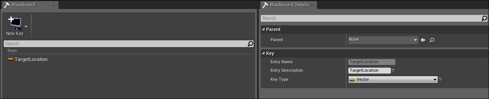
Behavior Tree is the logic path that NPC goes through to determine what course of action to take.
To create a Behavior Tree in Unreal Engine, go to Content Browser | Create | Miscellaneous, and then click on Behavior Tree. Rename it MyNPC_BT.

Double-click on MyNPC_BT to open the Behavior Tree editor. The following screenshot shows the setting that we want for MyNPC_BT. It should have MyNPC_Brain set as the BlackBoard asset. If it doesn't, search for MyNPC_Brain and assign it as the BlackBoard asset.
If you have already gone through the earlier exercise and are familiar with a Behavior Tree, you will notice that in this editor that there is a Root node, which you could use to start building out your NPC's behavior.

The next step here is to add on a composite node (either Sequence, Selector, or Simple Parallel). In this example, we will select and use a Sequence node to extend our Behavior Tree here. You can click and drag from the Root node to open up the contextual menu, as shown in the following screenshot. Alternatively, just right-click to open up the menu and select the node that you want to create.

We will add a Wait task from the Sequence node. Click and drag to create a new connection from the Sequence node. From the contextual menu, select Wait. Set Wait to be 15.0s, as shown in this screenshot. Save and compile MyNPC_BT.

After compiling, click on Play in the Behavior Tree editor. You would see the light moving through the links and especially from the Sequence node to the Wait task for 15s.
Now that we have a simple implementation of the Behavior Tree, we want our NPC character to start using it. How do we do this? Go to Content Browser | MyFolder, and double-click on MyNPC_AIController to open up the editor. Go to the EventGraph tab where we initially created a simple move forward implementation. Break the initial links between the IsValid node and Add Movement Input. Rewire them based on the following screenshot by linking the IsValid node to a new Run Behavior Tree node. In the Run Behavior Tree node, assign BTAsset to MyNPC_BT. Next, replace Event Tick with Event Begin Play (since the BT will now replace the thinking function here). Save and compile.

We want to now make the NPC select a location on the map and walk toward it.
This requires the creation of a custom task where the NPC has to select a target location. We have already created an entry in the BlackBoardData to store a vector value. However, we have not made a way to assign values to the data yet. This would be done by creating a custom Behavior Tree task.
Go to Content Browser | Create | Blueprint. For the parent class, search for BTNode and select BTTask_BlueprintBase, as shown in the following screenshot. Rename this task as Task_PickTargetLocation.

Double-click on the newly created Task_PickTargetLocation. Go to EventGraph, create the following nodes, and link these nodes:
- Event Receive Execute: Link Owner Actor to the target of Get Actor Location. When PickTargetLocation is executed, Event Receive Execute starts.
- Get Actor Location: Link Return Value to Origin of Get Random Point in the Radius node.
- Set Blackboard Value as Vector: Link Event Receive Execute to the execution arrow of Set Blackboard Value as Vector.
- Get Random Point in Radius: Link Return Value to the Value input for Set Blackboard Value as Vector.
- Finish Execute: Link Set Blackboard Value as Vector to the input execution of Finish Execute.
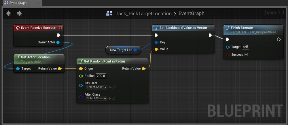
Notice that there is a
New Target Loc variable linked to Key of Set Blackboard Value as Vector. We need to create a new variable for this. Click on +Variable, as shown in the following screenshot, to create a new variable. Name the new variable New Target Loc.

Click on the newly created New Target Loc to display the details of the variable. Select BlackBoardKeySelector as the variable type, as shown in this screenshot:

Add a new link from the current Sequence composite node. Place the Task_PickTargetLocation node to the left of the Sequence node so that it would be executed first, as shown in the following screenshot. Make sure that New Target Loc is set as TargetLocation:

Delete the Wait node, and add the Move To node in its place. Make sure that Blackboard Key for Move To is set as TargetLocation, as show in this screenshot:

After compiling, click on Play to run the game. Double-click on MyNPC_BT to open the Behavior Tree editor. You would see the light moving through the links and the TargetLocation value changing in the Blackboard, as shown in this screenshot:

Remember to go back to the map level and see how the NPC is behaving now. The NPC now selects a target location and then move to the target location. Then, it selects a new target location and moves to another spot.
With this example, you have gained a detailed understanding of how to set up AI behavior and getting AI to work in your level. Challenge yourself to create more complex behaviors using the knowledge gained in this section.
I am sure you have noticed that we definitely need to create more complex behaviors to make a game interesting. In terms of implementation, it is often easier to implement more complex AI through a combination of programming and use the editor functions to take this a step further. So, it is important to know how AI can be triggered via the editor and how you can customize AI for your game.
Understanding a Behavior Tree
Learning how to design a good decision-making tree is very important. This is the foundation on which programmers or scripters rely to create the behavior of a character in a game. The Behavior Tree is the equivalent of a construction blueprint for architects who design your house.
A Behavior Tree has roots that branch out into layers of child nodes, which are ordered from left to right (this means that you always start from the left-most node when traversing the child nodes) that describe the decision-making process. The nodes that make up the Behavior Tree mainly fall into three categories: Composite, Decorator, or Leaf. Once you are familiar with a couple of the common types of nodes in each of the three categories, you would be ready to create your own complex behaviors:
|
Composite |
Decorator |
Leaf | |
|---|---|---|---|
|
Children nodes |
Having one or more children are possible. |
This can only have a single child node. |
This cannot have any children at all. |
|
Function |
Children nodes are processed, depending on the particular type of composite node. |
This either transforms results from a child node's status, terminates the child, or repeats the processing of the child, depending on the particular type of Decorator. |
This executes specific game actions/tasks or tests. |
|
Node examples |
The Sequence node processes the children nodes from the left-most child in sequence, collects results from each child, and passes the overall success or failure result over to the parent (note that even when only one child fails and the rest succeed, the overall result is failure). This can be thought of as an AND node. |
The Inverter node converts a success to a failure and pass this inverted result back to the parent. It works vice versa as well. |
The Shoot Once leaf node shows that the NPC would shoot once and return a success or failure, depending on the result. |
This is a simple walkthrough of how a Behavior Tree can be constructed. The following legend will help you identify the different components of a Behavior Tree:
The following figure shows a simple response for an enemy NPC. The enemy will only start attacking when the war starts.
The following figure has been expanded on the earlier Behavior Tree. It gives a more detailed description of how the enemy NPC should approach the target. The NPC will run towards the target (the player character in this case), and if it is close enough, it starts shooting the player.
Next, we set more behaviors that show how the NPC will shoot the player. We give the enemy NPC a little intelligence: hide if someone is shooting at it and start shooting if no one is shooting at it; if the player starts moving in toward it, the NPC starts moving backward to a better spot or goes for a death match (it shoots the player at close range).
The Unreal Editor allows complex Behavior Trees to be designed using the visual scripting Blueprints together with several AI components.
There is also an option in Unreal Engine 4 where very complex AI behaviors can be programmed in the conventional way or in combination with Blueprint visual scripting.
The nodes for BT in UE4 are broadly divided into five categories. Just to recap, we have already learned a little about the first four in the previous section; Service is the only new category here:
- Root: The starting node for a Behavior Tree and every Behavior Tree has only one root.
- Composite: These are the nodes that define the root of a branch and the base rules for how this branch is executed.
- Decorator: This is also known as a conditional. These attach themselves to another node and make decisions on whether or not a branch in the tree, or even a single node, can be executed.
- Task: This is also known as a Leaf in a typical BT. These are the leaves of the tree, that is, the nodes that "do" things.
- Service: These are attachments to composite nodes. They are executed at a defined frequency, as long as their branch is being executed. These are often used to make checks and update the Blackboard. These take the place of traditional parallel nodes in other Behavior Tree systems.
For AI characters to move around in the game level, we need to specifically tell the AI character which areas in the map are accessible.
Unreal Engine has implemented a mesh-like component known as Navigation Mesh. The Navigation Mesh is pretty much like a block volume; you could scale the size of the mesh to cover a specific area in the game level that an AI character can move around in. This limits the area in which an AI can go and makes the movement of the character more predictable.
Go to Modes | Volumes. Click and drop Nav Mesh Bounds Volume into your game level. The following screenshot shows where you can find Nav Mesh Bounds Volume in the editor:
If you are unable to see Nav Mesh Bounds Volume in your map, go to the Show settings within the editor, as shown in the following screenshot. Make sure the checkbox next to Navigation is checked:
Scale and move the Navigation Mesh to cover the area of the floor you want the AI character to be able to access. What I have done in the following screenshot is to scale the mesh to fit the floor area which I want my AI character to walk in. Translate the mesh upward and downward to allow it to be slightly above the actual ground mesh. The Navigation Mesh should sort of enclose the ground mesh. This screenshot shows how the mesh looks when it is visible:
Here's an overview of the components that we will create for this tutorial:
- Blueprint AIController (MyNPC_AIController)
- Blueprint Character (MyNPC_Character)
- BlackBoard (MyNPC_Brain)
- Behavior Tree (MyNPC_BT)
- Blueprint Behavior Tree Task (Task_PickTargetLocation)
The important takeaway from this tutorial is to learn how the components are linked up to work together to create logic; we make use of this logic to control the behavior of the NPC.
In terms of file structure in Content Browser for these different file types, you can group the different components into different folders. For this example, since we are only creating one NPC character with logic, I will put all these components into a single folder for simplicity. I created MyFolder under the main directory for this purpose.
We start creating the AI logic of our NPC starting with AIController and Character. The Character Blueprint is the object that contains the link to the mesh, and we will drag and drop this Character Blueprint into the level map after we make some initial configurations. The AIController is the component that gives the NPC character its logic.
We will discuss the rest of the other three components as we go along.
Go to Create | Blueprint. Type in AIController into the textbox to filter by class, as shown in the following screenshot. Select AIController as the parent class.
Rename this AIController Blueprint as MyNPC_AIController:
We will come back to configure this later.
Go to Create | Blueprint, and type in Character in the textbox to filter by class. Select Character as the parent class for the Blueprint, as shown in the following screenshot. Rename this Blueprint as MyNPC_Character.
Double-click on MyNPC_Character in Content Browser to open the Character Blueprint editor. Go to the Components tab.
In the Perspective space view, you will see an empty wireframe-capsule-shaped object, as shown in the following screenshot. In the Details panel in the Blueprint editor, scroll to the Mesh section, and we will add a mesh to this Blueprint by selecting an existing mesh we have. You can go to Content Browser, select HeroTPP, and click on the arrow next to it. Alternatively, you can click on the search button next to the box and find HeroTPP:
After selecting HeroTPP as the skeletal mesh, you will see the mesh appearing in the wireframe capsule. Notice that the HeroTPP skeletal mesh is much larger than the capsule wireframe, as shown in the following screenshot. We want to be able to adjust the size of the wireframe to surround the height and width of the skeletal mesh as closely as possible. This will define the collision volume of the character.
This figure shows when the wireframe for the skeletal mesh is the correct height:
Go to the Default tab of MyNPC_Character, scroll to the AI section, and click on the scroll box to display the options available for AIControllers. Select MyNPC_AIController to assign the character to use this AIController, as shown in this screenshot. Compile, save, and close MyNPC_Character for now.
Go to Content Browser, and click and drop MyNPC_Character into the level map. Compile and play the level. You will see that the character appears in the level but it is static.
Similar to the early implementation of assigning an animation to the mesh, we will add animation to MyNPC_Character. Double-click on MyNPC_Character to open the editor. Go the Default tab, scroll to the Animation section, and assign the Animation Blueprint (MyNPC_Blueprint), which we created earlier for this Character Blueprint. The following screenshot shows how we can assign animation to the character. Compile and save MyNPC_Character:
Now, play the level again, and you will see that the character is now walking on the spot (as we have set the speed to 100 in the Animation Blueprint, MyNPC_Blueprint).
Go to Content Browser. Then, go to MyFolder and double-click on MyNPC_AIController to open the editor. We will now add nodes in EventGraph to design the logic.
Our first mission is to get the character to move forward (instead of just walking on the same spot).
The following are the nodes to be added in EventGraph:
- Event Tick: This is used to trigger the loop to run at every tick
- Get Controlled Pawn: This returns the pawn of AIController (which will be the pawn of HeroTPP)
- Get Actor Forward Vector: This gets the forward vector
- Add Movement Input: This links the target to Get Controlled Pawn and Link World Direction to the output of Get Actor Forward Vector
- IsValid: This is to ensure that the pawn exists first before actually changing the pawn values
The following screenshot shows the final EventGraph that we want to create:
Now, play the level again, and you will see that the character is now walking forward. But it's doing this a little too quickly. We want to adjust the maximum speed at which the character moves.
Double-click on MyNPC_Character to open the editor. Go to the Default tab, scroll to the Character Movement section, and set Max Walk Speed to 100, as shown in this screenshot:
BlackBoardData functions as the memory unit of the brain of the NPC. This is where you store and retrieve data that would be used to control the behavior of the NPC. Go to Content Browser, and navigate to Create | Miscellaneous | Blackboard. Rename it MyNPC_Brain.
Behavior Tree is the logic path that NPC goes through to determine what course of action to take.
To create a Behavior Tree in Unreal Engine, go to Content Browser | Create | Miscellaneous, and then click on Behavior Tree. Rename it MyNPC_BT.
Double-click on MyNPC_BT to open the Behavior Tree editor. The following screenshot shows the setting that we want for MyNPC_BT. It should have MyNPC_Brain set as the BlackBoard asset. If it doesn't, search for MyNPC_Brain and assign it as the BlackBoard asset.
If you have already gone through the earlier exercise and are familiar with a Behavior Tree, you will notice that in this editor that there is a Root node, which you could use to start building out your NPC's behavior.
The next step here is to add on a composite node (either Sequence, Selector, or Simple Parallel). In this example, we will select and use a Sequence node to extend our Behavior Tree here. You can click and drag from the Root node to open up the contextual menu, as shown in the following screenshot. Alternatively, just right-click to open up the menu and select the node that you want to create.
We will add a Wait task from the Sequence node. Click and drag to create a new connection from the Sequence node. From the contextual menu, select Wait. Set Wait to be 15.0s, as shown in this screenshot. Save and compile MyNPC_BT.
After compiling, click on Play in the Behavior Tree editor. You would see the light moving through the links and especially from the Sequence node to the Wait task for 15s.
Now that we have a simple implementation of the Behavior Tree, we want our NPC character to start using it. How do we do this? Go to Content Browser | MyFolder, and double-click on MyNPC_AIController to open up the editor. Go to the EventGraph tab where we initially created a simple move forward implementation. Break the initial links between the IsValid node and Add Movement Input. Rewire them based on the following screenshot by linking the IsValid node to a new Run Behavior Tree node. In the Run Behavior Tree node, assign BTAsset to MyNPC_BT. Next, replace Event Tick with Event Begin Play (since the BT will now replace the thinking function here). Save and compile.
We want to now make the NPC select a location on the map and walk toward it.
This requires the creation of a custom task where the NPC has to select a target location. We have already created an entry in the BlackBoardData to store a vector value. However, we have not made a way to assign values to the data yet. This would be done by creating a custom Behavior Tree task.
Go to Content Browser | Create | Blueprint. For the parent class, search for BTNode and select BTTask_BlueprintBase, as shown in the following screenshot. Rename this task as Task_PickTargetLocation.
Double-click on the newly created Task_PickTargetLocation. Go to EventGraph, create the following nodes, and link these nodes:
- Event Receive Execute: Link Owner Actor to the target of Get Actor Location. When PickTargetLocation is executed, Event Receive Execute starts.
- Get Actor Location: Link Return Value to Origin of Get Random Point in the Radius node.
- Set Blackboard Value as Vector: Link Event Receive Execute to the execution arrow of Set Blackboard Value as Vector.
- Get Random Point in Radius: Link Return Value to the Value input for Set Blackboard Value as Vector.
- Finish Execute: Link Set Blackboard Value as Vector to the input execution of Finish Execute.
Notice that there is a
New Target Loc variable linked to Key of Set Blackboard Value as Vector. We need to create a new variable for this. Click on +Variable, as shown in the following screenshot, to create a new variable. Name the new variable New Target Loc.
Click on the newly created New Target Loc to display the details of the variable. Select BlackBoardKeySelector as the variable type, as shown in this screenshot:
Add a new link from the current Sequence composite node. Place the Task_PickTargetLocation node to the left of the Sequence node so that it would be executed first, as shown in the following screenshot. Make sure that New Target Loc is set as TargetLocation:
Delete the Wait node, and add the Move To node in its place. Make sure that Blackboard Key for Move To is set as TargetLocation, as show in this screenshot:
After compiling, click on Play to run the game. Double-click on MyNPC_BT to open the Behavior Tree editor. You would see the light moving through the links and the TargetLocation value changing in the Blackboard, as shown in this screenshot:
Remember to go back to the map level and see how the NPC is behaving now. The NPC now selects a target location and then move to the target location. Then, it selects a new target location and moves to another spot.
With this example, you have gained a detailed understanding of how to set up AI behavior and getting AI to work in your level. Challenge yourself to create more complex behaviors using the knowledge gained in this section.
I am sure you have noticed that we definitely need to create more complex behaviors to make a game interesting. In terms of implementation, it is often easier to implement more complex AI through a combination of programming and use the editor functions to take this a step further. So, it is important to know how AI can be triggered via the editor and how you can customize AI for your game.
Exercise – designing the logic of a Behavior Tree
This is a simple walkthrough of how a Behavior Tree can be constructed. The following legend will help you identify the different components of a Behavior Tree:
The following figure shows a simple response for an enemy NPC. The enemy will only start attacking when the war starts.
The following figure has been expanded on the earlier Behavior Tree. It gives a more detailed description of how the enemy NPC should approach the target. The NPC will run towards the target (the player character in this case), and if it is close enough, it starts shooting the player.
Next, we set more behaviors that show how the NPC will shoot the player. We give the enemy NPC a little intelligence: hide if someone is shooting at it and start shooting if no one is shooting at it; if the player starts moving in toward it, the NPC starts moving backward to a better spot or goes for a death match (it shoots the player at close range).
The Unreal Editor allows complex Behavior Trees to be designed using the visual scripting Blueprints together with several AI components.
There is also an option in Unreal Engine 4 where very complex AI behaviors can be programmed in the conventional way or in combination with Blueprint visual scripting.
The nodes for BT in UE4 are broadly divided into five categories. Just to recap, we have already learned a little about the first four in the previous section; Service is the only new category here:
- Root: The starting node for a Behavior Tree and every Behavior Tree has only one root.
- Composite: These are the nodes that define the root of a branch and the base rules for how this branch is executed.
- Decorator: This is also known as a conditional. These attach themselves to another node and make decisions on whether or not a branch in the tree, or even a single node, can be executed.
- Task: This is also known as a Leaf in a typical BT. These are the leaves of the tree, that is, the nodes that "do" things.
- Service: These are attachments to composite nodes. They are executed at a defined frequency, as long as their branch is being executed. These are often used to make checks and update the Blackboard. These take the place of traditional parallel nodes in other Behavior Tree systems.
For AI characters to move around in the game level, we need to specifically tell the AI character which areas in the map are accessible.
Unreal Engine has implemented a mesh-like component known as Navigation Mesh. The Navigation Mesh is pretty much like a block volume; you could scale the size of the mesh to cover a specific area in the game level that an AI character can move around in. This limits the area in which an AI can go and makes the movement of the character more predictable.
Go to Modes | Volumes. Click and drop Nav Mesh Bounds Volume into your game level. The following screenshot shows where you can find Nav Mesh Bounds Volume in the editor:
If you are unable to see Nav Mesh Bounds Volume in your map, go to the Show settings within the editor, as shown in the following screenshot. Make sure the checkbox next to Navigation is checked:
Scale and move the Navigation Mesh to cover the area of the floor you want the AI character to be able to access. What I have done in the following screenshot is to scale the mesh to fit the floor area which I want my AI character to walk in. Translate the mesh upward and downward to allow it to be slightly above the actual ground mesh. The Navigation Mesh should sort of enclose the ground mesh. This screenshot shows how the mesh looks when it is visible:
Here's an overview of the components that we will create for this tutorial:
- Blueprint AIController (MyNPC_AIController)
- Blueprint Character (MyNPC_Character)
- BlackBoard (MyNPC_Brain)
- Behavior Tree (MyNPC_BT)
- Blueprint Behavior Tree Task (Task_PickTargetLocation)
The important takeaway from this tutorial is to learn how the components are linked up to work together to create logic; we make use of this logic to control the behavior of the NPC.
In terms of file structure in Content Browser for these different file types, you can group the different components into different folders. For this example, since we are only creating one NPC character with logic, I will put all these components into a single folder for simplicity. I created MyFolder under the main directory for this purpose.
We start creating the AI logic of our NPC starting with AIController and Character. The Character Blueprint is the object that contains the link to the mesh, and we will drag and drop this Character Blueprint into the level map after we make some initial configurations. The AIController is the component that gives the NPC character its logic.
We will discuss the rest of the other three components as we go along.
Go to Create | Blueprint. Type in AIController into the textbox to filter by class, as shown in the following screenshot. Select AIController as the parent class.
Rename this AIController Blueprint as MyNPC_AIController:
We will come back to configure this later.
Go to Create | Blueprint, and type in Character in the textbox to filter by class. Select Character as the parent class for the Blueprint, as shown in the following screenshot. Rename this Blueprint as MyNPC_Character.
Double-click on MyNPC_Character in Content Browser to open the Character Blueprint editor. Go to the Components tab.
In the Perspective space view, you will see an empty wireframe-capsule-shaped object, as shown in the following screenshot. In the Details panel in the Blueprint editor, scroll to the Mesh section, and we will add a mesh to this Blueprint by selecting an existing mesh we have. You can go to Content Browser, select HeroTPP, and click on the arrow next to it. Alternatively, you can click on the search button next to the box and find HeroTPP:
After selecting HeroTPP as the skeletal mesh, you will see the mesh appearing in the wireframe capsule. Notice that the HeroTPP skeletal mesh is much larger than the capsule wireframe, as shown in the following screenshot. We want to be able to adjust the size of the wireframe to surround the height and width of the skeletal mesh as closely as possible. This will define the collision volume of the character.
This figure shows when the wireframe for the skeletal mesh is the correct height:
Go to the Default tab of MyNPC_Character, scroll to the AI section, and click on the scroll box to display the options available for AIControllers. Select MyNPC_AIController to assign the character to use this AIController, as shown in this screenshot. Compile, save, and close MyNPC_Character for now.
Go to Content Browser, and click and drop MyNPC_Character into the level map. Compile and play the level. You will see that the character appears in the level but it is static.
Similar to the early implementation of assigning an animation to the mesh, we will add animation to MyNPC_Character. Double-click on MyNPC_Character to open the editor. Go the Default tab, scroll to the Animation section, and assign the Animation Blueprint (MyNPC_Blueprint), which we created earlier for this Character Blueprint. The following screenshot shows how we can assign animation to the character. Compile and save MyNPC_Character:
Now, play the level again, and you will see that the character is now walking on the spot (as we have set the speed to 100 in the Animation Blueprint, MyNPC_Blueprint).
Go to Content Browser. Then, go to MyFolder and double-click on MyNPC_AIController to open the editor. We will now add nodes in EventGraph to design the logic.
Our first mission is to get the character to move forward (instead of just walking on the same spot).
The following are the nodes to be added in EventGraph:
- Event Tick: This is used to trigger the loop to run at every tick
- Get Controlled Pawn: This returns the pawn of AIController (which will be the pawn of HeroTPP)
- Get Actor Forward Vector: This gets the forward vector
- Add Movement Input: This links the target to Get Controlled Pawn and Link World Direction to the output of Get Actor Forward Vector
- IsValid: This is to ensure that the pawn exists first before actually changing the pawn values
The following screenshot shows the final EventGraph that we want to create:
Now, play the level again, and you will see that the character is now walking forward. But it's doing this a little too quickly. We want to adjust the maximum speed at which the character moves.
Double-click on MyNPC_Character to open the editor. Go to the Default tab, scroll to the Character Movement section, and set Max Walk Speed to 100, as shown in this screenshot:
BlackBoardData functions as the memory unit of the brain of the NPC. This is where you store and retrieve data that would be used to control the behavior of the NPC. Go to Content Browser, and navigate to Create | Miscellaneous | Blackboard. Rename it MyNPC_Brain.
Behavior Tree is the logic path that NPC goes through to determine what course of action to take.
To create a Behavior Tree in Unreal Engine, go to Content Browser | Create | Miscellaneous, and then click on Behavior Tree. Rename it MyNPC_BT.
Double-click on MyNPC_BT to open the Behavior Tree editor. The following screenshot shows the setting that we want for MyNPC_BT. It should have MyNPC_Brain set as the BlackBoard asset. If it doesn't, search for MyNPC_Brain and assign it as the BlackBoard asset.
If you have already gone through the earlier exercise and are familiar with a Behavior Tree, you will notice that in this editor that there is a Root node, which you could use to start building out your NPC's behavior.
The next step here is to add on a composite node (either Sequence, Selector, or Simple Parallel). In this example, we will select and use a Sequence node to extend our Behavior Tree here. You can click and drag from the Root node to open up the contextual menu, as shown in the following screenshot. Alternatively, just right-click to open up the menu and select the node that you want to create.
We will add a Wait task from the Sequence node. Click and drag to create a new connection from the Sequence node. From the contextual menu, select Wait. Set Wait to be 15.0s, as shown in this screenshot. Save and compile MyNPC_BT.
After compiling, click on Play in the Behavior Tree editor. You would see the light moving through the links and especially from the Sequence node to the Wait task for 15s.
Now that we have a simple implementation of the Behavior Tree, we want our NPC character to start using it. How do we do this? Go to Content Browser | MyFolder, and double-click on MyNPC_AIController to open up the editor. Go to the EventGraph tab where we initially created a simple move forward implementation. Break the initial links between the IsValid node and Add Movement Input. Rewire them based on the following screenshot by linking the IsValid node to a new Run Behavior Tree node. In the Run Behavior Tree node, assign BTAsset to MyNPC_BT. Next, replace Event Tick with Event Begin Play (since the BT will now replace the thinking function here). Save and compile.
We want to now make the NPC select a location on the map and walk toward it.
This requires the creation of a custom task where the NPC has to select a target location. We have already created an entry in the BlackBoardData to store a vector value. However, we have not made a way to assign values to the data yet. This would be done by creating a custom Behavior Tree task.
Go to Content Browser | Create | Blueprint. For the parent class, search for BTNode and select BTTask_BlueprintBase, as shown in the following screenshot. Rename this task as Task_PickTargetLocation.
Double-click on the newly created Task_PickTargetLocation. Go to EventGraph, create the following nodes, and link these nodes:
- Event Receive Execute: Link Owner Actor to the target of Get Actor Location. When PickTargetLocation is executed, Event Receive Execute starts.
- Get Actor Location: Link Return Value to Origin of Get Random Point in the Radius node.
- Set Blackboard Value as Vector: Link Event Receive Execute to the execution arrow of Set Blackboard Value as Vector.
- Get Random Point in Radius: Link Return Value to the Value input for Set Blackboard Value as Vector.
- Finish Execute: Link Set Blackboard Value as Vector to the input execution of Finish Execute.
Notice that there is a
New Target Loc variable linked to Key of Set Blackboard Value as Vector. We need to create a new variable for this. Click on +Variable, as shown in the following screenshot, to create a new variable. Name the new variable New Target Loc.
Click on the newly created New Target Loc to display the details of the variable. Select BlackBoardKeySelector as the variable type, as shown in this screenshot:
Add a new link from the current Sequence composite node. Place the Task_PickTargetLocation node to the left of the Sequence node so that it would be executed first, as shown in the following screenshot. Make sure that New Target Loc is set as TargetLocation:
Delete the Wait node, and add the Move To node in its place. Make sure that Blackboard Key for Move To is set as TargetLocation, as show in this screenshot:
After compiling, click on Play to run the game. Double-click on MyNPC_BT to open the Behavior Tree editor. You would see the light moving through the links and the TargetLocation value changing in the Blackboard, as shown in this screenshot:
Remember to go back to the map level and see how the NPC is behaving now. The NPC now selects a target location and then move to the target location. Then, it selects a new target location and moves to another spot.
With this example, you have gained a detailed understanding of how to set up AI behavior and getting AI to work in your level. Challenge yourself to create more complex behaviors using the knowledge gained in this section.
I am sure you have noticed that we definitely need to create more complex behaviors to make a game interesting. In terms of implementation, it is often easier to implement more complex AI through a combination of programming and use the editor functions to take this a step further. So, it is important to know how AI can be triggered via the editor and how you can customize AI for your game.
Example – creating a simple Behavior Tree
The following figure shows a simple response for an enemy NPC. The enemy will only start attacking when the war starts.
The following figure has been expanded on the earlier Behavior Tree. It gives a more detailed description of how the enemy NPC should approach the target. The NPC will run towards the target (the player character in this case), and if it is close enough, it starts shooting the player.
Next, we set more behaviors that show how the NPC will shoot the player. We give the enemy NPC a little intelligence: hide if someone is shooting at it and start shooting if no one is shooting at it; if the player starts moving in toward it, the NPC starts moving backward to a better spot or goes for a death match (it shoots the player at close range).
The Unreal Editor allows complex Behavior Trees to be designed using the visual scripting Blueprints together with several AI components.
There is also an option in Unreal Engine 4 where very complex AI behaviors can be programmed in the conventional way or in combination with Blueprint visual scripting.
The nodes for BT in UE4 are broadly divided into five categories. Just to recap, we have already learned a little about the first four in the previous section; Service is the only new category here:
- Root: The starting node for a Behavior Tree and every Behavior Tree has only one root.
- Composite: These are the nodes that define the root of a branch and the base rules for how this branch is executed.
- Decorator: This is also known as a conditional. These attach themselves to another node and make decisions on whether or not a branch in the tree, or even a single node, can be executed.
- Task: This is also known as a Leaf in a typical BT. These are the leaves of the tree, that is, the nodes that "do" things.
- Service: These are attachments to composite nodes. They are executed at a defined frequency, as long as their branch is being executed. These are often used to make checks and update the Blackboard. These take the place of traditional parallel nodes in other Behavior Tree systems.
For AI characters to move around in the game level, we need to specifically tell the AI character which areas in the map are accessible.
Unreal Engine has implemented a mesh-like component known as Navigation Mesh. The Navigation Mesh is pretty much like a block volume; you could scale the size of the mesh to cover a specific area in the game level that an AI character can move around in. This limits the area in which an AI can go and makes the movement of the character more predictable.
Go to Modes | Volumes. Click and drop Nav Mesh Bounds Volume into your game level. The following screenshot shows where you can find Nav Mesh Bounds Volume in the editor:
If you are unable to see Nav Mesh Bounds Volume in your map, go to the Show settings within the editor, as shown in the following screenshot. Make sure the checkbox next to Navigation is checked:
Scale and move the Navigation Mesh to cover the area of the floor you want the AI character to be able to access. What I have done in the following screenshot is to scale the mesh to fit the floor area which I want my AI character to walk in. Translate the mesh upward and downward to allow it to be slightly above the actual ground mesh. The Navigation Mesh should sort of enclose the ground mesh. This screenshot shows how the mesh looks when it is visible:
Here's an overview of the components that we will create for this tutorial:
- Blueprint AIController (MyNPC_AIController)
- Blueprint Character (MyNPC_Character)
- BlackBoard (MyNPC_Brain)
- Behavior Tree (MyNPC_BT)
- Blueprint Behavior Tree Task (Task_PickTargetLocation)
The important takeaway from this tutorial is to learn how the components are linked up to work together to create logic; we make use of this logic to control the behavior of the NPC.
In terms of file structure in Content Browser for these different file types, you can group the different components into different folders. For this example, since we are only creating one NPC character with logic, I will put all these components into a single folder for simplicity. I created MyFolder under the main directory for this purpose.
We start creating the AI logic of our NPC starting with AIController and Character. The Character Blueprint is the object that contains the link to the mesh, and we will drag and drop this Character Blueprint into the level map after we make some initial configurations. The AIController is the component that gives the NPC character its logic.
We will discuss the rest of the other three components as we go along.
Go to Create | Blueprint. Type in AIController into the textbox to filter by class, as shown in the following screenshot. Select AIController as the parent class.
Rename this AIController Blueprint as MyNPC_AIController:
We will come back to configure this later.
Go to Create | Blueprint, and type in Character in the textbox to filter by class. Select Character as the parent class for the Blueprint, as shown in the following screenshot. Rename this Blueprint as MyNPC_Character.
Double-click on MyNPC_Character in Content Browser to open the Character Blueprint editor. Go to the Components tab.
In the Perspective space view, you will see an empty wireframe-capsule-shaped object, as shown in the following screenshot. In the Details panel in the Blueprint editor, scroll to the Mesh section, and we will add a mesh to this Blueprint by selecting an existing mesh we have. You can go to Content Browser, select HeroTPP, and click on the arrow next to it. Alternatively, you can click on the search button next to the box and find HeroTPP:
After selecting HeroTPP as the skeletal mesh, you will see the mesh appearing in the wireframe capsule. Notice that the HeroTPP skeletal mesh is much larger than the capsule wireframe, as shown in the following screenshot. We want to be able to adjust the size of the wireframe to surround the height and width of the skeletal mesh as closely as possible. This will define the collision volume of the character.
This figure shows when the wireframe for the skeletal mesh is the correct height:
Go to the Default tab of MyNPC_Character, scroll to the AI section, and click on the scroll box to display the options available for AIControllers. Select MyNPC_AIController to assign the character to use this AIController, as shown in this screenshot. Compile, save, and close MyNPC_Character for now.
Go to Content Browser, and click and drop MyNPC_Character into the level map. Compile and play the level. You will see that the character appears in the level but it is static.
Similar to the early implementation of assigning an animation to the mesh, we will add animation to MyNPC_Character. Double-click on MyNPC_Character to open the editor. Go the Default tab, scroll to the Animation section, and assign the Animation Blueprint (MyNPC_Blueprint), which we created earlier for this Character Blueprint. The following screenshot shows how we can assign animation to the character. Compile and save MyNPC_Character:
Now, play the level again, and you will see that the character is now walking on the spot (as we have set the speed to 100 in the Animation Blueprint, MyNPC_Blueprint).
Go to Content Browser. Then, go to MyFolder and double-click on MyNPC_AIController to open the editor. We will now add nodes in EventGraph to design the logic.
Our first mission is to get the character to move forward (instead of just walking on the same spot).
The following are the nodes to be added in EventGraph:
- Event Tick: This is used to trigger the loop to run at every tick
- Get Controlled Pawn: This returns the pawn of AIController (which will be the pawn of HeroTPP)
- Get Actor Forward Vector: This gets the forward vector
- Add Movement Input: This links the target to Get Controlled Pawn and Link World Direction to the output of Get Actor Forward Vector
- IsValid: This is to ensure that the pawn exists first before actually changing the pawn values
The following screenshot shows the final EventGraph that we want to create:
Now, play the level again, and you will see that the character is now walking forward. But it's doing this a little too quickly. We want to adjust the maximum speed at which the character moves.
Double-click on MyNPC_Character to open the editor. Go to the Default tab, scroll to the Character Movement section, and set Max Walk Speed to 100, as shown in this screenshot:
BlackBoardData functions as the memory unit of the brain of the NPC. This is where you store and retrieve data that would be used to control the behavior of the NPC. Go to Content Browser, and navigate to Create | Miscellaneous | Blackboard. Rename it MyNPC_Brain.
Behavior Tree is the logic path that NPC goes through to determine what course of action to take.
To create a Behavior Tree in Unreal Engine, go to Content Browser | Create | Miscellaneous, and then click on Behavior Tree. Rename it MyNPC_BT.
Double-click on MyNPC_BT to open the Behavior Tree editor. The following screenshot shows the setting that we want for MyNPC_BT. It should have MyNPC_Brain set as the BlackBoard asset. If it doesn't, search for MyNPC_Brain and assign it as the BlackBoard asset.
If you have already gone through the earlier exercise and are familiar with a Behavior Tree, you will notice that in this editor that there is a Root node, which you could use to start building out your NPC's behavior.
The next step here is to add on a composite node (either Sequence, Selector, or Simple Parallel). In this example, we will select and use a Sequence node to extend our Behavior Tree here. You can click and drag from the Root node to open up the contextual menu, as shown in the following screenshot. Alternatively, just right-click to open up the menu and select the node that you want to create.
We will add a Wait task from the Sequence node. Click and drag to create a new connection from the Sequence node. From the contextual menu, select Wait. Set Wait to be 15.0s, as shown in this screenshot. Save and compile MyNPC_BT.
After compiling, click on Play in the Behavior Tree editor. You would see the light moving through the links and especially from the Sequence node to the Wait task for 15s.
Now that we have a simple implementation of the Behavior Tree, we want our NPC character to start using it. How do we do this? Go to Content Browser | MyFolder, and double-click on MyNPC_AIController to open up the editor. Go to the EventGraph tab where we initially created a simple move forward implementation. Break the initial links between the IsValid node and Add Movement Input. Rewire them based on the following screenshot by linking the IsValid node to a new Run Behavior Tree node. In the Run Behavior Tree node, assign BTAsset to MyNPC_BT. Next, replace Event Tick with Event Begin Play (since the BT will now replace the thinking function here). Save and compile.
We want to now make the NPC select a location on the map and walk toward it.
This requires the creation of a custom task where the NPC has to select a target location. We have already created an entry in the BlackBoardData to store a vector value. However, we have not made a way to assign values to the data yet. This would be done by creating a custom Behavior Tree task.
Go to Content Browser | Create | Blueprint. For the parent class, search for BTNode and select BTTask_BlueprintBase, as shown in the following screenshot. Rename this task as Task_PickTargetLocation.
Double-click on the newly created Task_PickTargetLocation. Go to EventGraph, create the following nodes, and link these nodes:
- Event Receive Execute: Link Owner Actor to the target of Get Actor Location. When PickTargetLocation is executed, Event Receive Execute starts.
- Get Actor Location: Link Return Value to Origin of Get Random Point in the Radius node.
- Set Blackboard Value as Vector: Link Event Receive Execute to the execution arrow of Set Blackboard Value as Vector.
- Get Random Point in Radius: Link Return Value to the Value input for Set Blackboard Value as Vector.
- Finish Execute: Link Set Blackboard Value as Vector to the input execution of Finish Execute.
Notice that there is a
New Target Loc variable linked to Key of Set Blackboard Value as Vector. We need to create a new variable for this. Click on +Variable, as shown in the following screenshot, to create a new variable. Name the new variable New Target Loc.
Click on the newly created New Target Loc to display the details of the variable. Select BlackBoardKeySelector as the variable type, as shown in this screenshot:
Add a new link from the current Sequence composite node. Place the Task_PickTargetLocation node to the left of the Sequence node so that it would be executed first, as shown in the following screenshot. Make sure that New Target Loc is set as TargetLocation:
Delete the Wait node, and add the Move To node in its place. Make sure that Blackboard Key for Move To is set as TargetLocation, as show in this screenshot:
After compiling, click on Play to run the game. Double-click on MyNPC_BT to open the Behavior Tree editor. You would see the light moving through the links and the TargetLocation value changing in the Blackboard, as shown in this screenshot:
Remember to go back to the map level and see how the NPC is behaving now. The NPC now selects a target location and then move to the target location. Then, it selects a new target location and moves to another spot.
With this example, you have gained a detailed understanding of how to set up AI behavior and getting AI to work in your level. Challenge yourself to create more complex behaviors using the knowledge gained in this section.
I am sure you have noticed that we definitely need to create more complex behaviors to make a game interesting. In terms of implementation, it is often easier to implement more complex AI through a combination of programming and use the editor functions to take this a step further. So, it is important to know how AI can be triggered via the editor and how you can customize AI for your game.
How to implement a Behavior Tree in Unreal Engine 4
The Unreal Editor allows complex Behavior Trees to be designed using the visual scripting Blueprints together with several AI components.
There is also an option in Unreal Engine 4 where very complex AI behaviors can be programmed in the conventional way or in combination with Blueprint visual scripting.
The nodes for BT in UE4 are broadly divided into five categories. Just to recap, we have already learned a little about the first four in the previous section; Service is the only new category here:
- Root: The starting node for a Behavior Tree and every Behavior Tree has only one root.
- Composite: These are the nodes that define the root of a branch and the base rules for how this branch is executed.
- Decorator: This is also known as a conditional. These attach themselves to another node and make decisions on whether or not a branch in the tree, or even a single node, can be executed.
- Task: This is also known as a Leaf in a typical BT. These are the leaves of the tree, that is, the nodes that "do" things.
- Service: These are attachments to composite nodes. They are executed at a defined frequency, as long as their branch is being executed. These are often used to make checks and update the Blackboard. These take the place of traditional parallel nodes in other Behavior Tree systems.
For AI characters to move around in the game level, we need to specifically tell the AI character which areas in the map are accessible.
Unreal Engine has implemented a mesh-like component known as Navigation Mesh. The Navigation Mesh is pretty much like a block volume; you could scale the size of the mesh to cover a specific area in the game level that an AI character can move around in. This limits the area in which an AI can go and makes the movement of the character more predictable.
Go to Modes | Volumes. Click and drop Nav Mesh Bounds Volume into your game level. The following screenshot shows where you can find Nav Mesh Bounds Volume in the editor:
If you are unable to see Nav Mesh Bounds Volume in your map, go to the Show settings within the editor, as shown in the following screenshot. Make sure the checkbox next to Navigation is checked:
Scale and move the Navigation Mesh to cover the area of the floor you want the AI character to be able to access. What I have done in the following screenshot is to scale the mesh to fit the floor area which I want my AI character to walk in. Translate the mesh upward and downward to allow it to be slightly above the actual ground mesh. The Navigation Mesh should sort of enclose the ground mesh. This screenshot shows how the mesh looks when it is visible:
Here's an overview of the components that we will create for this tutorial:
- Blueprint AIController (MyNPC_AIController)
- Blueprint Character (MyNPC_Character)
- BlackBoard (MyNPC_Brain)
- Behavior Tree (MyNPC_BT)
- Blueprint Behavior Tree Task (Task_PickTargetLocation)
The important takeaway from this tutorial is to learn how the components are linked up to work together to create logic; we make use of this logic to control the behavior of the NPC.
In terms of file structure in Content Browser for these different file types, you can group the different components into different folders. For this example, since we are only creating one NPC character with logic, I will put all these components into a single folder for simplicity. I created MyFolder under the main directory for this purpose.
We start creating the AI logic of our NPC starting with AIController and Character. The Character Blueprint is the object that contains the link to the mesh, and we will drag and drop this Character Blueprint into the level map after we make some initial configurations. The AIController is the component that gives the NPC character its logic.
We will discuss the rest of the other three components as we go along.
Go to Create | Blueprint. Type in AIController into the textbox to filter by class, as shown in the following screenshot. Select AIController as the parent class.
Rename this AIController Blueprint as MyNPC_AIController:
We will come back to configure this later.
Go to Create | Blueprint, and type in Character in the textbox to filter by class. Select Character as the parent class for the Blueprint, as shown in the following screenshot. Rename this Blueprint as MyNPC_Character.
Double-click on MyNPC_Character in Content Browser to open the Character Blueprint editor. Go to the Components tab.
In the Perspective space view, you will see an empty wireframe-capsule-shaped object, as shown in the following screenshot. In the Details panel in the Blueprint editor, scroll to the Mesh section, and we will add a mesh to this Blueprint by selecting an existing mesh we have. You can go to Content Browser, select HeroTPP, and click on the arrow next to it. Alternatively, you can click on the search button next to the box and find HeroTPP:
After selecting HeroTPP as the skeletal mesh, you will see the mesh appearing in the wireframe capsule. Notice that the HeroTPP skeletal mesh is much larger than the capsule wireframe, as shown in the following screenshot. We want to be able to adjust the size of the wireframe to surround the height and width of the skeletal mesh as closely as possible. This will define the collision volume of the character.
This figure shows when the wireframe for the skeletal mesh is the correct height:
Go to the Default tab of MyNPC_Character, scroll to the AI section, and click on the scroll box to display the options available for AIControllers. Select MyNPC_AIController to assign the character to use this AIController, as shown in this screenshot. Compile, save, and close MyNPC_Character for now.
Go to Content Browser, and click and drop MyNPC_Character into the level map. Compile and play the level. You will see that the character appears in the level but it is static.
Similar to the early implementation of assigning an animation to the mesh, we will add animation to MyNPC_Character. Double-click on MyNPC_Character to open the editor. Go the Default tab, scroll to the Animation section, and assign the Animation Blueprint (MyNPC_Blueprint), which we created earlier for this Character Blueprint. The following screenshot shows how we can assign animation to the character. Compile and save MyNPC_Character:
Now, play the level again, and you will see that the character is now walking on the spot (as we have set the speed to 100 in the Animation Blueprint, MyNPC_Blueprint).
Go to Content Browser. Then, go to MyFolder and double-click on MyNPC_AIController to open the editor. We will now add nodes in EventGraph to design the logic.
Our first mission is to get the character to move forward (instead of just walking on the same spot).
The following are the nodes to be added in EventGraph:
- Event Tick: This is used to trigger the loop to run at every tick
- Get Controlled Pawn: This returns the pawn of AIController (which will be the pawn of HeroTPP)
- Get Actor Forward Vector: This gets the forward vector
- Add Movement Input: This links the target to Get Controlled Pawn and Link World Direction to the output of Get Actor Forward Vector
- IsValid: This is to ensure that the pawn exists first before actually changing the pawn values
The following screenshot shows the final EventGraph that we want to create:
Now, play the level again, and you will see that the character is now walking forward. But it's doing this a little too quickly. We want to adjust the maximum speed at which the character moves.
Double-click on MyNPC_Character to open the editor. Go to the Default tab, scroll to the Character Movement section, and set Max Walk Speed to 100, as shown in this screenshot:
BlackBoardData functions as the memory unit of the brain of the NPC. This is where you store and retrieve data that would be used to control the behavior of the NPC. Go to Content Browser, and navigate to Create | Miscellaneous | Blackboard. Rename it MyNPC_Brain.
Behavior Tree is the logic path that NPC goes through to determine what course of action to take.
To create a Behavior Tree in Unreal Engine, go to Content Browser | Create | Miscellaneous, and then click on Behavior Tree. Rename it MyNPC_BT.
Double-click on MyNPC_BT to open the Behavior Tree editor. The following screenshot shows the setting that we want for MyNPC_BT. It should have MyNPC_Brain set as the BlackBoard asset. If it doesn't, search for MyNPC_Brain and assign it as the BlackBoard asset.
If you have already gone through the earlier exercise and are familiar with a Behavior Tree, you will notice that in this editor that there is a Root node, which you could use to start building out your NPC's behavior.
The next step here is to add on a composite node (either Sequence, Selector, or Simple Parallel). In this example, we will select and use a Sequence node to extend our Behavior Tree here. You can click and drag from the Root node to open up the contextual menu, as shown in the following screenshot. Alternatively, just right-click to open up the menu and select the node that you want to create.
We will add a Wait task from the Sequence node. Click and drag to create a new connection from the Sequence node. From the contextual menu, select Wait. Set Wait to be 15.0s, as shown in this screenshot. Save and compile MyNPC_BT.
After compiling, click on Play in the Behavior Tree editor. You would see the light moving through the links and especially from the Sequence node to the Wait task for 15s.
Now that we have a simple implementation of the Behavior Tree, we want our NPC character to start using it. How do we do this? Go to Content Browser | MyFolder, and double-click on MyNPC_AIController to open up the editor. Go to the EventGraph tab where we initially created a simple move forward implementation. Break the initial links between the IsValid node and Add Movement Input. Rewire them based on the following screenshot by linking the IsValid node to a new Run Behavior Tree node. In the Run Behavior Tree node, assign BTAsset to MyNPC_BT. Next, replace Event Tick with Event Begin Play (since the BT will now replace the thinking function here). Save and compile.
We want to now make the NPC select a location on the map and walk toward it.
This requires the creation of a custom task where the NPC has to select a target location. We have already created an entry in the BlackBoardData to store a vector value. However, we have not made a way to assign values to the data yet. This would be done by creating a custom Behavior Tree task.
Go to Content Browser | Create | Blueprint. For the parent class, search for BTNode and select BTTask_BlueprintBase, as shown in the following screenshot. Rename this task as Task_PickTargetLocation.
Double-click on the newly created Task_PickTargetLocation. Go to EventGraph, create the following nodes, and link these nodes:
- Event Receive Execute: Link Owner Actor to the target of Get Actor Location. When PickTargetLocation is executed, Event Receive Execute starts.
- Get Actor Location: Link Return Value to Origin of Get Random Point in the Radius node.
- Set Blackboard Value as Vector: Link Event Receive Execute to the execution arrow of Set Blackboard Value as Vector.
- Get Random Point in Radius: Link Return Value to the Value input for Set Blackboard Value as Vector.
- Finish Execute: Link Set Blackboard Value as Vector to the input execution of Finish Execute.
Notice that there is a
New Target Loc variable linked to Key of Set Blackboard Value as Vector. We need to create a new variable for this. Click on +Variable, as shown in the following screenshot, to create a new variable. Name the new variable New Target Loc.
Click on the newly created New Target Loc to display the details of the variable. Select BlackBoardKeySelector as the variable type, as shown in this screenshot:
Add a new link from the current Sequence composite node. Place the Task_PickTargetLocation node to the left of the Sequence node so that it would be executed first, as shown in the following screenshot. Make sure that New Target Loc is set as TargetLocation:
Delete the Wait node, and add the Move To node in its place. Make sure that Blackboard Key for Move To is set as TargetLocation, as show in this screenshot:
After compiling, click on Play to run the game. Double-click on MyNPC_BT to open the Behavior Tree editor. You would see the light moving through the links and the TargetLocation value changing in the Blackboard, as shown in this screenshot:
Remember to go back to the map level and see how the NPC is behaving now. The NPC now selects a target location and then move to the target location. Then, it selects a new target location and moves to another spot.
With this example, you have gained a detailed understanding of how to set up AI behavior and getting AI to work in your level. Challenge yourself to create more complex behaviors using the knowledge gained in this section.
I am sure you have noticed that we definitely need to create more complex behaviors to make a game interesting. In terms of implementation, it is often easier to implement more complex AI through a combination of programming and use the editor functions to take this a step further. So, it is important to know how AI can be triggered via the editor and how you can customize AI for your game.
Navigation Mesh
For AI characters to move around in the game level, we need to specifically tell the AI character which areas in the map are accessible.
Unreal Engine has implemented a mesh-like component known as Navigation Mesh. The Navigation Mesh is pretty much like a block volume; you could scale the size of the mesh to cover a specific area in the game level that an AI character can move around in. This limits the area in which an AI can go and makes the movement of the character more predictable.
Go to Modes | Volumes. Click and drop Nav Mesh Bounds Volume into your game level. The following screenshot shows where you can find Nav Mesh Bounds Volume in the editor:
If you are unable to see Nav Mesh Bounds Volume in your map, go to the Show settings within the editor, as shown in the following screenshot. Make sure the checkbox next to Navigation is checked:
Scale and move the Navigation Mesh to cover the area of the floor you want the AI character to be able to access. What I have done in the following screenshot is to scale the mesh to fit the floor area which I want my AI character to walk in. Translate the mesh upward and downward to allow it to be slightly above the actual ground mesh. The Navigation Mesh should sort of enclose the ground mesh. This screenshot shows how the mesh looks when it is visible:
Here's an overview of the components that we will create for this tutorial:
- Blueprint AIController (MyNPC_AIController)
- Blueprint Character (MyNPC_Character)
- BlackBoard (MyNPC_Brain)
- Behavior Tree (MyNPC_BT)
- Blueprint Behavior Tree Task (Task_PickTargetLocation)
The important takeaway from this tutorial is to learn how the components are linked up to work together to create logic; we make use of this logic to control the behavior of the NPC.
In terms of file structure in Content Browser for these different file types, you can group the different components into different folders. For this example, since we are only creating one NPC character with logic, I will put all these components into a single folder for simplicity. I created MyFolder under the main directory for this purpose.
We start creating the AI logic of our NPC starting with AIController and Character. The Character Blueprint is the object that contains the link to the mesh, and we will drag and drop this Character Blueprint into the level map after we make some initial configurations. The AIController is the component that gives the NPC character its logic.
We will discuss the rest of the other three components as we go along.
Go to Create | Blueprint. Type in AIController into the textbox to filter by class, as shown in the following screenshot. Select AIController as the parent class.
Rename this AIController Blueprint as MyNPC_AIController:
We will come back to configure this later.
Go to Create | Blueprint, and type in Character in the textbox to filter by class. Select Character as the parent class for the Blueprint, as shown in the following screenshot. Rename this Blueprint as MyNPC_Character.
Double-click on MyNPC_Character in Content Browser to open the Character Blueprint editor. Go to the Components tab.
In the Perspective space view, you will see an empty wireframe-capsule-shaped object, as shown in the following screenshot. In the Details panel in the Blueprint editor, scroll to the Mesh section, and we will add a mesh to this Blueprint by selecting an existing mesh we have. You can go to Content Browser, select HeroTPP, and click on the arrow next to it. Alternatively, you can click on the search button next to the box and find HeroTPP:
After selecting HeroTPP as the skeletal mesh, you will see the mesh appearing in the wireframe capsule. Notice that the HeroTPP skeletal mesh is much larger than the capsule wireframe, as shown in the following screenshot. We want to be able to adjust the size of the wireframe to surround the height and width of the skeletal mesh as closely as possible. This will define the collision volume of the character.
This figure shows when the wireframe for the skeletal mesh is the correct height:
Go to the Default tab of MyNPC_Character, scroll to the AI section, and click on the scroll box to display the options available for AIControllers. Select MyNPC_AIController to assign the character to use this AIController, as shown in this screenshot. Compile, save, and close MyNPC_Character for now.
Go to Content Browser, and click and drop MyNPC_Character into the level map. Compile and play the level. You will see that the character appears in the level but it is static.
Similar to the early implementation of assigning an animation to the mesh, we will add animation to MyNPC_Character. Double-click on MyNPC_Character to open the editor. Go the Default tab, scroll to the Animation section, and assign the Animation Blueprint (MyNPC_Blueprint), which we created earlier for this Character Blueprint. The following screenshot shows how we can assign animation to the character. Compile and save MyNPC_Character:
Now, play the level again, and you will see that the character is now walking on the spot (as we have set the speed to 100 in the Animation Blueprint, MyNPC_Blueprint).
Go to Content Browser. Then, go to MyFolder and double-click on MyNPC_AIController to open the editor. We will now add nodes in EventGraph to design the logic.
Our first mission is to get the character to move forward (instead of just walking on the same spot).
The following are the nodes to be added in EventGraph:
- Event Tick: This is used to trigger the loop to run at every tick
- Get Controlled Pawn: This returns the pawn of AIController (which will be the pawn of HeroTPP)
- Get Actor Forward Vector: This gets the forward vector
- Add Movement Input: This links the target to Get Controlled Pawn and Link World Direction to the output of Get Actor Forward Vector
- IsValid: This is to ensure that the pawn exists first before actually changing the pawn values
The following screenshot shows the final EventGraph that we want to create:
Now, play the level again, and you will see that the character is now walking forward. But it's doing this a little too quickly. We want to adjust the maximum speed at which the character moves.
Double-click on MyNPC_Character to open the editor. Go to the Default tab, scroll to the Character Movement section, and set Max Walk Speed to 100, as shown in this screenshot:
BlackBoardData functions as the memory unit of the brain of the NPC. This is where you store and retrieve data that would be used to control the behavior of the NPC. Go to Content Browser, and navigate to Create | Miscellaneous | Blackboard. Rename it MyNPC_Brain.
Behavior Tree is the logic path that NPC goes through to determine what course of action to take.
To create a Behavior Tree in Unreal Engine, go to Content Browser | Create | Miscellaneous, and then click on Behavior Tree. Rename it MyNPC_BT.
Double-click on MyNPC_BT to open the Behavior Tree editor. The following screenshot shows the setting that we want for MyNPC_BT. It should have MyNPC_Brain set as the BlackBoard asset. If it doesn't, search for MyNPC_Brain and assign it as the BlackBoard asset.
If you have already gone through the earlier exercise and are familiar with a Behavior Tree, you will notice that in this editor that there is a Root node, which you could use to start building out your NPC's behavior.
The next step here is to add on a composite node (either Sequence, Selector, or Simple Parallel). In this example, we will select and use a Sequence node to extend our Behavior Tree here. You can click and drag from the Root node to open up the contextual menu, as shown in the following screenshot. Alternatively, just right-click to open up the menu and select the node that you want to create.
We will add a Wait task from the Sequence node. Click and drag to create a new connection from the Sequence node. From the contextual menu, select Wait. Set Wait to be 15.0s, as shown in this screenshot. Save and compile MyNPC_BT.
After compiling, click on Play in the Behavior Tree editor. You would see the light moving through the links and especially from the Sequence node to the Wait task for 15s.
Now that we have a simple implementation of the Behavior Tree, we want our NPC character to start using it. How do we do this? Go to Content Browser | MyFolder, and double-click on MyNPC_AIController to open up the editor. Go to the EventGraph tab where we initially created a simple move forward implementation. Break the initial links between the IsValid node and Add Movement Input. Rewire them based on the following screenshot by linking the IsValid node to a new Run Behavior Tree node. In the Run Behavior Tree node, assign BTAsset to MyNPC_BT. Next, replace Event Tick with Event Begin Play (since the BT will now replace the thinking function here). Save and compile.
We want to now make the NPC select a location on the map and walk toward it.
This requires the creation of a custom task where the NPC has to select a target location. We have already created an entry in the BlackBoardData to store a vector value. However, we have not made a way to assign values to the data yet. This would be done by creating a custom Behavior Tree task.
Go to Content Browser | Create | Blueprint. For the parent class, search for BTNode and select BTTask_BlueprintBase, as shown in the following screenshot. Rename this task as Task_PickTargetLocation.
Double-click on the newly created Task_PickTargetLocation. Go to EventGraph, create the following nodes, and link these nodes:
- Event Receive Execute: Link Owner Actor to the target of Get Actor Location. When PickTargetLocation is executed, Event Receive Execute starts.
- Get Actor Location: Link Return Value to Origin of Get Random Point in the Radius node.
- Set Blackboard Value as Vector: Link Event Receive Execute to the execution arrow of Set Blackboard Value as Vector.
- Get Random Point in Radius: Link Return Value to the Value input for Set Blackboard Value as Vector.
- Finish Execute: Link Set Blackboard Value as Vector to the input execution of Finish Execute.
Notice that there is a
New Target Loc variable linked to Key of Set Blackboard Value as Vector. We need to create a new variable for this. Click on +Variable, as shown in the following screenshot, to create a new variable. Name the new variable New Target Loc.
Click on the newly created New Target Loc to display the details of the variable. Select BlackBoardKeySelector as the variable type, as shown in this screenshot:
Add a new link from the current Sequence composite node. Place the Task_PickTargetLocation node to the left of the Sequence node so that it would be executed first, as shown in the following screenshot. Make sure that New Target Loc is set as TargetLocation:
Delete the Wait node, and add the Move To node in its place. Make sure that Blackboard Key for Move To is set as TargetLocation, as show in this screenshot:
After compiling, click on Play to run the game. Double-click on MyNPC_BT to open the Behavior Tree editor. You would see the light moving through the links and the TargetLocation value changing in the Blackboard, as shown in this screenshot:
Remember to go back to the map level and see how the NPC is behaving now. The NPC now selects a target location and then move to the target location. Then, it selects a new target location and moves to another spot.
With this example, you have gained a detailed understanding of how to set up AI behavior and getting AI to work in your level. Challenge yourself to create more complex behaviors using the knowledge gained in this section.
I am sure you have noticed that we definitely need to create more complex behaviors to make a game interesting. In terms of implementation, it is often easier to implement more complex AI through a combination of programming and use the editor functions to take this a step further. So, it is important to know how AI can be triggered via the editor and how you can customize AI for your game.
Tutorial – creating a Navigation Mesh
Go to Modes | Volumes. Click and drop Nav Mesh Bounds Volume into your game level. The following screenshot shows where you can find Nav Mesh Bounds Volume in the editor:
If you are unable to see Nav Mesh Bounds Volume in your map, go to the Show settings within the editor, as shown in the following screenshot. Make sure the checkbox next to Navigation is checked:
Scale and move the Navigation Mesh to cover the area of the floor you want the AI character to be able to access. What I have done in the following screenshot is to scale the mesh to fit the floor area which I want my AI character to walk in. Translate the mesh upward and downward to allow it to be slightly above the actual ground mesh. The Navigation Mesh should sort of enclose the ground mesh. This screenshot shows how the mesh looks when it is visible:
Here's an overview of the components that we will create for this tutorial:
- Blueprint AIController (MyNPC_AIController)
- Blueprint Character (MyNPC_Character)
- BlackBoard (MyNPC_Brain)
- Behavior Tree (MyNPC_BT)
- Blueprint Behavior Tree Task (Task_PickTargetLocation)
The important takeaway from this tutorial is to learn how the components are linked up to work together to create logic; we make use of this logic to control the behavior of the NPC.
In terms of file structure in Content Browser for these different file types, you can group the different components into different folders. For this example, since we are only creating one NPC character with logic, I will put all these components into a single folder for simplicity. I created MyFolder under the main directory for this purpose.
We start creating the AI logic of our NPC starting with AIController and Character. The Character Blueprint is the object that contains the link to the mesh, and we will drag and drop this Character Blueprint into the level map after we make some initial configurations. The AIController is the component that gives the NPC character its logic.
We will discuss the rest of the other three components as we go along.
Go to Create | Blueprint. Type in AIController into the textbox to filter by class, as shown in the following screenshot. Select AIController as the parent class.
Rename this AIController Blueprint as MyNPC_AIController:
We will come back to configure this later.
Go to Create | Blueprint, and type in Character in the textbox to filter by class. Select Character as the parent class for the Blueprint, as shown in the following screenshot. Rename this Blueprint as MyNPC_Character.
Double-click on MyNPC_Character in Content Browser to open the Character Blueprint editor. Go to the Components tab.
In the Perspective space view, you will see an empty wireframe-capsule-shaped object, as shown in the following screenshot. In the Details panel in the Blueprint editor, scroll to the Mesh section, and we will add a mesh to this Blueprint by selecting an existing mesh we have. You can go to Content Browser, select HeroTPP, and click on the arrow next to it. Alternatively, you can click on the search button next to the box and find HeroTPP:
After selecting HeroTPP as the skeletal mesh, you will see the mesh appearing in the wireframe capsule. Notice that the HeroTPP skeletal mesh is much larger than the capsule wireframe, as shown in the following screenshot. We want to be able to adjust the size of the wireframe to surround the height and width of the skeletal mesh as closely as possible. This will define the collision volume of the character.
This figure shows when the wireframe for the skeletal mesh is the correct height:
Go to the Default tab of MyNPC_Character, scroll to the AI section, and click on the scroll box to display the options available for AIControllers. Select MyNPC_AIController to assign the character to use this AIController, as shown in this screenshot. Compile, save, and close MyNPC_Character for now.
Go to Content Browser, and click and drop MyNPC_Character into the level map. Compile and play the level. You will see that the character appears in the level but it is static.
Similar to the early implementation of assigning an animation to the mesh, we will add animation to MyNPC_Character. Double-click on MyNPC_Character to open the editor. Go the Default tab, scroll to the Animation section, and assign the Animation Blueprint (MyNPC_Blueprint), which we created earlier for this Character Blueprint. The following screenshot shows how we can assign animation to the character. Compile and save MyNPC_Character:
Now, play the level again, and you will see that the character is now walking on the spot (as we have set the speed to 100 in the Animation Blueprint, MyNPC_Blueprint).
Go to Content Browser. Then, go to MyFolder and double-click on MyNPC_AIController to open the editor. We will now add nodes in EventGraph to design the logic.
Our first mission is to get the character to move forward (instead of just walking on the same spot).
The following are the nodes to be added in EventGraph:
- Event Tick: This is used to trigger the loop to run at every tick
- Get Controlled Pawn: This returns the pawn of AIController (which will be the pawn of HeroTPP)
- Get Actor Forward Vector: This gets the forward vector
- Add Movement Input: This links the target to Get Controlled Pawn and Link World Direction to the output of Get Actor Forward Vector
- IsValid: This is to ensure that the pawn exists first before actually changing the pawn values
The following screenshot shows the final EventGraph that we want to create:
Now, play the level again, and you will see that the character is now walking forward. But it's doing this a little too quickly. We want to adjust the maximum speed at which the character moves.
Double-click on MyNPC_Character to open the editor. Go to the Default tab, scroll to the Character Movement section, and set Max Walk Speed to 100, as shown in this screenshot:
BlackBoardData functions as the memory unit of the brain of the NPC. This is where you store and retrieve data that would be used to control the behavior of the NPC. Go to Content Browser, and navigate to Create | Miscellaneous | Blackboard. Rename it MyNPC_Brain.
Behavior Tree is the logic path that NPC goes through to determine what course of action to take.
To create a Behavior Tree in Unreal Engine, go to Content Browser | Create | Miscellaneous, and then click on Behavior Tree. Rename it MyNPC_BT.
Double-click on MyNPC_BT to open the Behavior Tree editor. The following screenshot shows the setting that we want for MyNPC_BT. It should have MyNPC_Brain set as the BlackBoard asset. If it doesn't, search for MyNPC_Brain and assign it as the BlackBoard asset.
If you have already gone through the earlier exercise and are familiar with a Behavior Tree, you will notice that in this editor that there is a Root node, which you could use to start building out your NPC's behavior.
The next step here is to add on a composite node (either Sequence, Selector, or Simple Parallel). In this example, we will select and use a Sequence node to extend our Behavior Tree here. You can click and drag from the Root node to open up the contextual menu, as shown in the following screenshot. Alternatively, just right-click to open up the menu and select the node that you want to create.
We will add a Wait task from the Sequence node. Click and drag to create a new connection from the Sequence node. From the contextual menu, select Wait. Set Wait to be 15.0s, as shown in this screenshot. Save and compile MyNPC_BT.
After compiling, click on Play in the Behavior Tree editor. You would see the light moving through the links and especially from the Sequence node to the Wait task for 15s.
Now that we have a simple implementation of the Behavior Tree, we want our NPC character to start using it. How do we do this? Go to Content Browser | MyFolder, and double-click on MyNPC_AIController to open up the editor. Go to the EventGraph tab where we initially created a simple move forward implementation. Break the initial links between the IsValid node and Add Movement Input. Rewire them based on the following screenshot by linking the IsValid node to a new Run Behavior Tree node. In the Run Behavior Tree node, assign BTAsset to MyNPC_BT. Next, replace Event Tick with Event Begin Play (since the BT will now replace the thinking function here). Save and compile.
We want to now make the NPC select a location on the map and walk toward it.
This requires the creation of a custom task where the NPC has to select a target location. We have already created an entry in the BlackBoardData to store a vector value. However, we have not made a way to assign values to the data yet. This would be done by creating a custom Behavior Tree task.
Go to Content Browser | Create | Blueprint. For the parent class, search for BTNode and select BTTask_BlueprintBase, as shown in the following screenshot. Rename this task as Task_PickTargetLocation.
Double-click on the newly created Task_PickTargetLocation. Go to EventGraph, create the following nodes, and link these nodes:
- Event Receive Execute: Link Owner Actor to the target of Get Actor Location. When PickTargetLocation is executed, Event Receive Execute starts.
- Get Actor Location: Link Return Value to Origin of Get Random Point in the Radius node.
- Set Blackboard Value as Vector: Link Event Receive Execute to the execution arrow of Set Blackboard Value as Vector.
- Get Random Point in Radius: Link Return Value to the Value input for Set Blackboard Value as Vector.
- Finish Execute: Link Set Blackboard Value as Vector to the input execution of Finish Execute.
Notice that there is a
New Target Loc variable linked to Key of Set Blackboard Value as Vector. We need to create a new variable for this. Click on +Variable, as shown in the following screenshot, to create a new variable. Name the new variable New Target Loc.
Click on the newly created New Target Loc to display the details of the variable. Select BlackBoardKeySelector as the variable type, as shown in this screenshot:
Add a new link from the current Sequence composite node. Place the Task_PickTargetLocation node to the left of the Sequence node so that it would be executed first, as shown in the following screenshot. Make sure that New Target Loc is set as TargetLocation:
Delete the Wait node, and add the Move To node in its place. Make sure that Blackboard Key for Move To is set as TargetLocation, as show in this screenshot:
After compiling, click on Play to run the game. Double-click on MyNPC_BT to open the Behavior Tree editor. You would see the light moving through the links and the TargetLocation value changing in the Blackboard, as shown in this screenshot:
Remember to go back to the map level and see how the NPC is behaving now. The NPC now selects a target location and then move to the target location. Then, it selects a new target location and moves to another spot.
With this example, you have gained a detailed understanding of how to set up AI behavior and getting AI to work in your level. Challenge yourself to create more complex behaviors using the knowledge gained in this section.
I am sure you have noticed that we definitely need to create more complex behaviors to make a game interesting. In terms of implementation, it is often easier to implement more complex AI through a combination of programming and use the editor functions to take this a step further. So, it is important to know how AI can be triggered via the editor and how you can customize AI for your game.
Tutorial – setting up AI logic
Here's an overview of the components that we will create for this tutorial:
- Blueprint AIController (MyNPC_AIController)
- Blueprint Character (MyNPC_Character)
- BlackBoard (MyNPC_Brain)
- Behavior Tree (MyNPC_BT)
- Blueprint Behavior Tree Task (Task_PickTargetLocation)
The important takeaway from this tutorial is to learn how the components are linked up to work together to create logic; we make use of this logic to control the behavior of the NPC.
In terms of file structure in Content Browser for these different file types, you can group the different components into different folders. For this example, since we are only creating one NPC character with logic, I will put all these components into a single folder for simplicity. I created MyFolder under the main directory for this purpose.
We start creating the AI logic of our NPC starting with AIController and Character. The Character Blueprint is the object that contains the link to the mesh, and we will drag and drop this Character Blueprint into the level map after we make some initial configurations. The AIController is the component that gives the NPC character its logic.
We will discuss the rest of the other three components as we go along.
Go to Create | Blueprint. Type in AIController into the textbox to filter by class, as shown in the following screenshot. Select AIController as the parent class.
Rename this AIController Blueprint as MyNPC_AIController:
We will come back to configure this later.
Go to Create | Blueprint, and type in Character in the textbox to filter by class. Select Character as the parent class for the Blueprint, as shown in the following screenshot. Rename this Blueprint as MyNPC_Character.
Double-click on MyNPC_Character in Content Browser to open the Character Blueprint editor. Go to the Components tab.
In the Perspective space view, you will see an empty wireframe-capsule-shaped object, as shown in the following screenshot. In the Details panel in the Blueprint editor, scroll to the Mesh section, and we will add a mesh to this Blueprint by selecting an existing mesh we have. You can go to Content Browser, select HeroTPP, and click on the arrow next to it. Alternatively, you can click on the search button next to the box and find HeroTPP:
After selecting HeroTPP as the skeletal mesh, you will see the mesh appearing in the wireframe capsule. Notice that the HeroTPP skeletal mesh is much larger than the capsule wireframe, as shown in the following screenshot. We want to be able to adjust the size of the wireframe to surround the height and width of the skeletal mesh as closely as possible. This will define the collision volume of the character.
This figure shows when the wireframe for the skeletal mesh is the correct height:
Go to the Default tab of MyNPC_Character, scroll to the AI section, and click on the scroll box to display the options available for AIControllers. Select MyNPC_AIController to assign the character to use this AIController, as shown in this screenshot. Compile, save, and close MyNPC_Character for now.
Go to Content Browser, and click and drop MyNPC_Character into the level map. Compile and play the level. You will see that the character appears in the level but it is static.
Similar to the early implementation of assigning an animation to the mesh, we will add animation to MyNPC_Character. Double-click on MyNPC_Character to open the editor. Go the Default tab, scroll to the Animation section, and assign the Animation Blueprint (MyNPC_Blueprint), which we created earlier for this Character Blueprint. The following screenshot shows how we can assign animation to the character. Compile and save MyNPC_Character:
Now, play the level again, and you will see that the character is now walking on the spot (as we have set the speed to 100 in the Animation Blueprint, MyNPC_Blueprint).
Go to Content Browser. Then, go to MyFolder and double-click on MyNPC_AIController to open the editor. We will now add nodes in EventGraph to design the logic.
Our first mission is to get the character to move forward (instead of just walking on the same spot).
The following are the nodes to be added in EventGraph:
- Event Tick: This is used to trigger the loop to run at every tick
- Get Controlled Pawn: This returns the pawn of AIController (which will be the pawn of HeroTPP)
- Get Actor Forward Vector: This gets the forward vector
- Add Movement Input: This links the target to Get Controlled Pawn and Link World Direction to the output of Get Actor Forward Vector
- IsValid: This is to ensure that the pawn exists first before actually changing the pawn values
The following screenshot shows the final EventGraph that we want to create:
Now, play the level again, and you will see that the character is now walking forward. But it's doing this a little too quickly. We want to adjust the maximum speed at which the character moves.
Double-click on MyNPC_Character to open the editor. Go to the Default tab, scroll to the Character Movement section, and set Max Walk Speed to 100, as shown in this screenshot:
BlackBoardData functions as the memory unit of the brain of the NPC. This is where you store and retrieve data that would be used to control the behavior of the NPC. Go to Content Browser, and navigate to Create | Miscellaneous | Blackboard. Rename it MyNPC_Brain.
Behavior Tree is the logic path that NPC goes through to determine what course of action to take.
To create a Behavior Tree in Unreal Engine, go to Content Browser | Create | Miscellaneous, and then click on Behavior Tree. Rename it MyNPC_BT.
Double-click on MyNPC_BT to open the Behavior Tree editor. The following screenshot shows the setting that we want for MyNPC_BT. It should have MyNPC_Brain set as the BlackBoard asset. If it doesn't, search for MyNPC_Brain and assign it as the BlackBoard asset.
If you have already gone through the earlier exercise and are familiar with a Behavior Tree, you will notice that in this editor that there is a Root node, which you could use to start building out your NPC's behavior.
The next step here is to add on a composite node (either Sequence, Selector, or Simple Parallel). In this example, we will select and use a Sequence node to extend our Behavior Tree here. You can click and drag from the Root node to open up the contextual menu, as shown in the following screenshot. Alternatively, just right-click to open up the menu and select the node that you want to create.
We will add a Wait task from the Sequence node. Click and drag to create a new connection from the Sequence node. From the contextual menu, select Wait. Set Wait to be 15.0s, as shown in this screenshot. Save and compile MyNPC_BT.
After compiling, click on Play in the Behavior Tree editor. You would see the light moving through the links and especially from the Sequence node to the Wait task for 15s.
Now that we have a simple implementation of the Behavior Tree, we want our NPC character to start using it. How do we do this? Go to Content Browser | MyFolder, and double-click on MyNPC_AIController to open up the editor. Go to the EventGraph tab where we initially created a simple move forward implementation. Break the initial links between the IsValid node and Add Movement Input. Rewire them based on the following screenshot by linking the IsValid node to a new Run Behavior Tree node. In the Run Behavior Tree node, assign BTAsset to MyNPC_BT. Next, replace Event Tick with Event Begin Play (since the BT will now replace the thinking function here). Save and compile.
We want to now make the NPC select a location on the map and walk toward it.
This requires the creation of a custom task where the NPC has to select a target location. We have already created an entry in the BlackBoardData to store a vector value. However, we have not made a way to assign values to the data yet. This would be done by creating a custom Behavior Tree task.
Go to Content Browser | Create | Blueprint. For the parent class, search for BTNode and select BTTask_BlueprintBase, as shown in the following screenshot. Rename this task as Task_PickTargetLocation.
Double-click on the newly created Task_PickTargetLocation. Go to EventGraph, create the following nodes, and link these nodes:
- Event Receive Execute: Link Owner Actor to the target of Get Actor Location. When PickTargetLocation is executed, Event Receive Execute starts.
- Get Actor Location: Link Return Value to Origin of Get Random Point in the Radius node.
- Set Blackboard Value as Vector: Link Event Receive Execute to the execution arrow of Set Blackboard Value as Vector.
- Get Random Point in Radius: Link Return Value to the Value input for Set Blackboard Value as Vector.
- Finish Execute: Link Set Blackboard Value as Vector to the input execution of Finish Execute.
Notice that there is a
New Target Loc variable linked to Key of Set Blackboard Value as Vector. We need to create a new variable for this. Click on +Variable, as shown in the following screenshot, to create a new variable. Name the new variable New Target Loc.
Click on the newly created New Target Loc to display the details of the variable. Select BlackBoardKeySelector as the variable type, as shown in this screenshot:
Add a new link from the current Sequence composite node. Place the Task_PickTargetLocation node to the left of the Sequence node so that it would be executed first, as shown in the following screenshot. Make sure that New Target Loc is set as TargetLocation:
Delete the Wait node, and add the Move To node in its place. Make sure that Blackboard Key for Move To is set as TargetLocation, as show in this screenshot:
After compiling, click on Play to run the game. Double-click on MyNPC_BT to open the Behavior Tree editor. You would see the light moving through the links and the TargetLocation value changing in the Blackboard, as shown in this screenshot:
Remember to go back to the map level and see how the NPC is behaving now. The NPC now selects a target location and then move to the target location. Then, it selects a new target location and moves to another spot.
With this example, you have gained a detailed understanding of how to set up AI behavior and getting AI to work in your level. Challenge yourself to create more complex behaviors using the knowledge gained in this section.
I am sure you have noticed that we definitely need to create more complex behaviors to make a game interesting. In terms of implementation, it is often easier to implement more complex AI through a combination of programming and use the editor functions to take this a step further. So, it is important to know how AI can be triggered via the editor and how you can customize AI for your game.
Creating the Blueprint AIController
Go to Create | Blueprint. Type in AIController into the textbox to filter by class, as shown in the following screenshot. Select AIController as the parent class.
Rename this AIController Blueprint as MyNPC_AIController:
We will come back to configure this later.
Go to Create | Blueprint, and type in Character in the textbox to filter by class. Select Character as the parent class for the Blueprint, as shown in the following screenshot. Rename this Blueprint as MyNPC_Character.
Double-click on MyNPC_Character in Content Browser to open the Character Blueprint editor. Go to the Components tab.
In the Perspective space view, you will see an empty wireframe-capsule-shaped object, as shown in the following screenshot. In the Details panel in the Blueprint editor, scroll to the Mesh section, and we will add a mesh to this Blueprint by selecting an existing mesh we have. You can go to Content Browser, select HeroTPP, and click on the arrow next to it. Alternatively, you can click on the search button next to the box and find HeroTPP:
After selecting HeroTPP as the skeletal mesh, you will see the mesh appearing in the wireframe capsule. Notice that the HeroTPP skeletal mesh is much larger than the capsule wireframe, as shown in the following screenshot. We want to be able to adjust the size of the wireframe to surround the height and width of the skeletal mesh as closely as possible. This will define the collision volume of the character.
This figure shows when the wireframe for the skeletal mesh is the correct height:
Go to the Default tab of MyNPC_Character, scroll to the AI section, and click on the scroll box to display the options available for AIControllers. Select MyNPC_AIController to assign the character to use this AIController, as shown in this screenshot. Compile, save, and close MyNPC_Character for now.
Go to Content Browser, and click and drop MyNPC_Character into the level map. Compile and play the level. You will see that the character appears in the level but it is static.
Similar to the early implementation of assigning an animation to the mesh, we will add animation to MyNPC_Character. Double-click on MyNPC_Character to open the editor. Go the Default tab, scroll to the Animation section, and assign the Animation Blueprint (MyNPC_Blueprint), which we created earlier for this Character Blueprint. The following screenshot shows how we can assign animation to the character. Compile and save MyNPC_Character:
Now, play the level again, and you will see that the character is now walking on the spot (as we have set the speed to 100 in the Animation Blueprint, MyNPC_Blueprint).
Go to Content Browser. Then, go to MyFolder and double-click on MyNPC_AIController to open the editor. We will now add nodes in EventGraph to design the logic.
Our first mission is to get the character to move forward (instead of just walking on the same spot).
The following are the nodes to be added in EventGraph:
- Event Tick: This is used to trigger the loop to run at every tick
- Get Controlled Pawn: This returns the pawn of AIController (which will be the pawn of HeroTPP)
- Get Actor Forward Vector: This gets the forward vector
- Add Movement Input: This links the target to Get Controlled Pawn and Link World Direction to the output of Get Actor Forward Vector
- IsValid: This is to ensure that the pawn exists first before actually changing the pawn values
The following screenshot shows the final EventGraph that we want to create:
Now, play the level again, and you will see that the character is now walking forward. But it's doing this a little too quickly. We want to adjust the maximum speed at which the character moves.
Double-click on MyNPC_Character to open the editor. Go to the Default tab, scroll to the Character Movement section, and set Max Walk Speed to 100, as shown in this screenshot:
BlackBoardData functions as the memory unit of the brain of the NPC. This is where you store and retrieve data that would be used to control the behavior of the NPC. Go to Content Browser, and navigate to Create | Miscellaneous | Blackboard. Rename it MyNPC_Brain.
Behavior Tree is the logic path that NPC goes through to determine what course of action to take.
To create a Behavior Tree in Unreal Engine, go to Content Browser | Create | Miscellaneous, and then click on Behavior Tree. Rename it MyNPC_BT.
Double-click on MyNPC_BT to open the Behavior Tree editor. The following screenshot shows the setting that we want for MyNPC_BT. It should have MyNPC_Brain set as the BlackBoard asset. If it doesn't, search for MyNPC_Brain and assign it as the BlackBoard asset.
If you have already gone through the earlier exercise and are familiar with a Behavior Tree, you will notice that in this editor that there is a Root node, which you could use to start building out your NPC's behavior.
The next step here is to add on a composite node (either Sequence, Selector, or Simple Parallel). In this example, we will select and use a Sequence node to extend our Behavior Tree here. You can click and drag from the Root node to open up the contextual menu, as shown in the following screenshot. Alternatively, just right-click to open up the menu and select the node that you want to create.
We will add a Wait task from the Sequence node. Click and drag to create a new connection from the Sequence node. From the contextual menu, select Wait. Set Wait to be 15.0s, as shown in this screenshot. Save and compile MyNPC_BT.
After compiling, click on Play in the Behavior Tree editor. You would see the light moving through the links and especially from the Sequence node to the Wait task for 15s.
Now that we have a simple implementation of the Behavior Tree, we want our NPC character to start using it. How do we do this? Go to Content Browser | MyFolder, and double-click on MyNPC_AIController to open up the editor. Go to the EventGraph tab where we initially created a simple move forward implementation. Break the initial links between the IsValid node and Add Movement Input. Rewire them based on the following screenshot by linking the IsValid node to a new Run Behavior Tree node. In the Run Behavior Tree node, assign BTAsset to MyNPC_BT. Next, replace Event Tick with Event Begin Play (since the BT will now replace the thinking function here). Save and compile.
We want to now make the NPC select a location on the map and walk toward it.
This requires the creation of a custom task where the NPC has to select a target location. We have already created an entry in the BlackBoardData to store a vector value. However, we have not made a way to assign values to the data yet. This would be done by creating a custom Behavior Tree task.
Go to Content Browser | Create | Blueprint. For the parent class, search for BTNode and select BTTask_BlueprintBase, as shown in the following screenshot. Rename this task as Task_PickTargetLocation.
Double-click on the newly created Task_PickTargetLocation. Go to EventGraph, create the following nodes, and link these nodes:
- Event Receive Execute: Link Owner Actor to the target of Get Actor Location. When PickTargetLocation is executed, Event Receive Execute starts.
- Get Actor Location: Link Return Value to Origin of Get Random Point in the Radius node.
- Set Blackboard Value as Vector: Link Event Receive Execute to the execution arrow of Set Blackboard Value as Vector.
- Get Random Point in Radius: Link Return Value to the Value input for Set Blackboard Value as Vector.
- Finish Execute: Link Set Blackboard Value as Vector to the input execution of Finish Execute.
Notice that there is a
New Target Loc variable linked to Key of Set Blackboard Value as Vector. We need to create a new variable for this. Click on +Variable, as shown in the following screenshot, to create a new variable. Name the new variable New Target Loc.
Click on the newly created New Target Loc to display the details of the variable. Select BlackBoardKeySelector as the variable type, as shown in this screenshot:
Add a new link from the current Sequence composite node. Place the Task_PickTargetLocation node to the left of the Sequence node so that it would be executed first, as shown in the following screenshot. Make sure that New Target Loc is set as TargetLocation:
Delete the Wait node, and add the Move To node in its place. Make sure that Blackboard Key for Move To is set as TargetLocation, as show in this screenshot:
After compiling, click on Play to run the game. Double-click on MyNPC_BT to open the Behavior Tree editor. You would see the light moving through the links and the TargetLocation value changing in the Blackboard, as shown in this screenshot:
Remember to go back to the map level and see how the NPC is behaving now. The NPC now selects a target location and then move to the target location. Then, it selects a new target location and moves to another spot.
With this example, you have gained a detailed understanding of how to set up AI behavior and getting AI to work in your level. Challenge yourself to create more complex behaviors using the knowledge gained in this section.
I am sure you have noticed that we definitely need to create more complex behaviors to make a game interesting. In terms of implementation, it is often easier to implement more complex AI through a combination of programming and use the editor functions to take this a step further. So, it is important to know how AI can be triggered via the editor and how you can customize AI for your game.
Creating the Blueprint character
Go to Create | Blueprint, and type in Character in the textbox to filter by class. Select Character as the parent class for the Blueprint, as shown in the following screenshot. Rename this Blueprint as MyNPC_Character.
Double-click on MyNPC_Character in Content Browser to open the Character Blueprint editor. Go to the Components tab.
In the Perspective space view, you will see an empty wireframe-capsule-shaped object, as shown in the following screenshot. In the Details panel in the Blueprint editor, scroll to the Mesh section, and we will add a mesh to this Blueprint by selecting an existing mesh we have. You can go to Content Browser, select HeroTPP, and click on the arrow next to it. Alternatively, you can click on the search button next to the box and find HeroTPP:
After selecting HeroTPP as the skeletal mesh, you will see the mesh appearing in the wireframe capsule. Notice that the HeroTPP skeletal mesh is much larger than the capsule wireframe, as shown in the following screenshot. We want to be able to adjust the size of the wireframe to surround the height and width of the skeletal mesh as closely as possible. This will define the collision volume of the character.
This figure shows when the wireframe for the skeletal mesh is the correct height:
Go to the Default tab of MyNPC_Character, scroll to the AI section, and click on the scroll box to display the options available for AIControllers. Select MyNPC_AIController to assign the character to use this AIController, as shown in this screenshot. Compile, save, and close MyNPC_Character for now.
Go to Content Browser, and click and drop MyNPC_Character into the level map. Compile and play the level. You will see that the character appears in the level but it is static.
Similar to the early implementation of assigning an animation to the mesh, we will add animation to MyNPC_Character. Double-click on MyNPC_Character to open the editor. Go the Default tab, scroll to the Animation section, and assign the Animation Blueprint (MyNPC_Blueprint), which we created earlier for this Character Blueprint. The following screenshot shows how we can assign animation to the character. Compile and save MyNPC_Character:
Now, play the level again, and you will see that the character is now walking on the spot (as we have set the speed to 100 in the Animation Blueprint, MyNPC_Blueprint).
Go to Content Browser. Then, go to MyFolder and double-click on MyNPC_AIController to open the editor. We will now add nodes in EventGraph to design the logic.
Our first mission is to get the character to move forward (instead of just walking on the same spot).
The following are the nodes to be added in EventGraph:
- Event Tick: This is used to trigger the loop to run at every tick
- Get Controlled Pawn: This returns the pawn of AIController (which will be the pawn of HeroTPP)
- Get Actor Forward Vector: This gets the forward vector
- Add Movement Input: This links the target to Get Controlled Pawn and Link World Direction to the output of Get Actor Forward Vector
- IsValid: This is to ensure that the pawn exists first before actually changing the pawn values
The following screenshot shows the final EventGraph that we want to create:
Now, play the level again, and you will see that the character is now walking forward. But it's doing this a little too quickly. We want to adjust the maximum speed at which the character moves.
Double-click on MyNPC_Character to open the editor. Go to the Default tab, scroll to the Character Movement section, and set Max Walk Speed to 100, as shown in this screenshot:
BlackBoardData functions as the memory unit of the brain of the NPC. This is where you store and retrieve data that would be used to control the behavior of the NPC. Go to Content Browser, and navigate to Create | Miscellaneous | Blackboard. Rename it MyNPC_Brain.
Behavior Tree is the logic path that NPC goes through to determine what course of action to take.
To create a Behavior Tree in Unreal Engine, go to Content Browser | Create | Miscellaneous, and then click on Behavior Tree. Rename it MyNPC_BT.
Double-click on MyNPC_BT to open the Behavior Tree editor. The following screenshot shows the setting that we want for MyNPC_BT. It should have MyNPC_Brain set as the BlackBoard asset. If it doesn't, search for MyNPC_Brain and assign it as the BlackBoard asset.
If you have already gone through the earlier exercise and are familiar with a Behavior Tree, you will notice that in this editor that there is a Root node, which you could use to start building out your NPC's behavior.
The next step here is to add on a composite node (either Sequence, Selector, or Simple Parallel). In this example, we will select and use a Sequence node to extend our Behavior Tree here. You can click and drag from the Root node to open up the contextual menu, as shown in the following screenshot. Alternatively, just right-click to open up the menu and select the node that you want to create.
We will add a Wait task from the Sequence node. Click and drag to create a new connection from the Sequence node. From the contextual menu, select Wait. Set Wait to be 15.0s, as shown in this screenshot. Save and compile MyNPC_BT.
After compiling, click on Play in the Behavior Tree editor. You would see the light moving through the links and especially from the Sequence node to the Wait task for 15s.
Now that we have a simple implementation of the Behavior Tree, we want our NPC character to start using it. How do we do this? Go to Content Browser | MyFolder, and double-click on MyNPC_AIController to open up the editor. Go to the EventGraph tab where we initially created a simple move forward implementation. Break the initial links between the IsValid node and Add Movement Input. Rewire them based on the following screenshot by linking the IsValid node to a new Run Behavior Tree node. In the Run Behavior Tree node, assign BTAsset to MyNPC_BT. Next, replace Event Tick with Event Begin Play (since the BT will now replace the thinking function here). Save and compile.
We want to now make the NPC select a location on the map and walk toward it.
This requires the creation of a custom task where the NPC has to select a target location. We have already created an entry in the BlackBoardData to store a vector value. However, we have not made a way to assign values to the data yet. This would be done by creating a custom Behavior Tree task.
Go to Content Browser | Create | Blueprint. For the parent class, search for BTNode and select BTTask_BlueprintBase, as shown in the following screenshot. Rename this task as Task_PickTargetLocation.
Double-click on the newly created Task_PickTargetLocation. Go to EventGraph, create the following nodes, and link these nodes:
- Event Receive Execute: Link Owner Actor to the target of Get Actor Location. When PickTargetLocation is executed, Event Receive Execute starts.
- Get Actor Location: Link Return Value to Origin of Get Random Point in the Radius node.
- Set Blackboard Value as Vector: Link Event Receive Execute to the execution arrow of Set Blackboard Value as Vector.
- Get Random Point in Radius: Link Return Value to the Value input for Set Blackboard Value as Vector.
- Finish Execute: Link Set Blackboard Value as Vector to the input execution of Finish Execute.
Notice that there is a
New Target Loc variable linked to Key of Set Blackboard Value as Vector. We need to create a new variable for this. Click on +Variable, as shown in the following screenshot, to create a new variable. Name the new variable New Target Loc.
Click on the newly created New Target Loc to display the details of the variable. Select BlackBoardKeySelector as the variable type, as shown in this screenshot:
Add a new link from the current Sequence composite node. Place the Task_PickTargetLocation node to the left of the Sequence node so that it would be executed first, as shown in the following screenshot. Make sure that New Target Loc is set as TargetLocation:
Delete the Wait node, and add the Move To node in its place. Make sure that Blackboard Key for Move To is set as TargetLocation, as show in this screenshot:
After compiling, click on Play to run the game. Double-click on MyNPC_BT to open the Behavior Tree editor. You would see the light moving through the links and the TargetLocation value changing in the Blackboard, as shown in this screenshot:
Remember to go back to the map level and see how the NPC is behaving now. The NPC now selects a target location and then move to the target location. Then, it selects a new target location and moves to another spot.
With this example, you have gained a detailed understanding of how to set up AI behavior and getting AI to work in your level. Challenge yourself to create more complex behaviors using the knowledge gained in this section.
I am sure you have noticed that we definitely need to create more complex behaviors to make a game interesting. In terms of implementation, it is often easier to implement more complex AI through a combination of programming and use the editor functions to take this a step further. So, it is important to know how AI can be triggered via the editor and how you can customize AI for your game.
Adding and configuring Mesh to a Character Blueprint
Double-click on MyNPC_Character in Content Browser to open the Character Blueprint editor. Go to the Components tab.
In the Perspective space view, you will see an empty wireframe-capsule-shaped object, as shown in the following screenshot. In the Details panel in the Blueprint editor, scroll to the Mesh section, and we will add a mesh to this Blueprint by selecting an existing mesh we have. You can go to Content Browser, select HeroTPP, and click on the arrow next to it. Alternatively, you can click on the search button next to the box and find HeroTPP:
After selecting HeroTPP as the skeletal mesh, you will see the mesh appearing in the wireframe capsule. Notice that the HeroTPP skeletal mesh is much larger than the capsule wireframe, as shown in the following screenshot. We want to be able to adjust the size of the wireframe to surround the height and width of the skeletal mesh as closely as possible. This will define the collision volume of the character.
This figure shows when the wireframe for the skeletal mesh is the correct height:
Go to the Default tab of MyNPC_Character, scroll to the AI section, and click on the scroll box to display the options available for AIControllers. Select MyNPC_AIController to assign the character to use this AIController, as shown in this screenshot. Compile, save, and close MyNPC_Character for now.
Go to Content Browser, and click and drop MyNPC_Character into the level map. Compile and play the level. You will see that the character appears in the level but it is static.
Similar to the early implementation of assigning an animation to the mesh, we will add animation to MyNPC_Character. Double-click on MyNPC_Character to open the editor. Go the Default tab, scroll to the Animation section, and assign the Animation Blueprint (MyNPC_Blueprint), which we created earlier for this Character Blueprint. The following screenshot shows how we can assign animation to the character. Compile and save MyNPC_Character:
Now, play the level again, and you will see that the character is now walking on the spot (as we have set the speed to 100 in the Animation Blueprint, MyNPC_Blueprint).
Go to Content Browser. Then, go to MyFolder and double-click on MyNPC_AIController to open the editor. We will now add nodes in EventGraph to design the logic.
Our first mission is to get the character to move forward (instead of just walking on the same spot).
The following are the nodes to be added in EventGraph:
- Event Tick: This is used to trigger the loop to run at every tick
- Get Controlled Pawn: This returns the pawn of AIController (which will be the pawn of HeroTPP)
- Get Actor Forward Vector: This gets the forward vector
- Add Movement Input: This links the target to Get Controlled Pawn and Link World Direction to the output of Get Actor Forward Vector
- IsValid: This is to ensure that the pawn exists first before actually changing the pawn values
The following screenshot shows the final EventGraph that we want to create:
Now, play the level again, and you will see that the character is now walking forward. But it's doing this a little too quickly. We want to adjust the maximum speed at which the character moves.
Double-click on MyNPC_Character to open the editor. Go to the Default tab, scroll to the Character Movement section, and set Max Walk Speed to 100, as shown in this screenshot:
BlackBoardData functions as the memory unit of the brain of the NPC. This is where you store and retrieve data that would be used to control the behavior of the NPC. Go to Content Browser, and navigate to Create | Miscellaneous | Blackboard. Rename it MyNPC_Brain.
Behavior Tree is the logic path that NPC goes through to determine what course of action to take.
To create a Behavior Tree in Unreal Engine, go to Content Browser | Create | Miscellaneous, and then click on Behavior Tree. Rename it MyNPC_BT.
Double-click on MyNPC_BT to open the Behavior Tree editor. The following screenshot shows the setting that we want for MyNPC_BT. It should have MyNPC_Brain set as the BlackBoard asset. If it doesn't, search for MyNPC_Brain and assign it as the BlackBoard asset.
If you have already gone through the earlier exercise and are familiar with a Behavior Tree, you will notice that in this editor that there is a Root node, which you could use to start building out your NPC's behavior.
The next step here is to add on a composite node (either Sequence, Selector, or Simple Parallel). In this example, we will select and use a Sequence node to extend our Behavior Tree here. You can click and drag from the Root node to open up the contextual menu, as shown in the following screenshot. Alternatively, just right-click to open up the menu and select the node that you want to create.
We will add a Wait task from the Sequence node. Click and drag to create a new connection from the Sequence node. From the contextual menu, select Wait. Set Wait to be 15.0s, as shown in this screenshot. Save and compile MyNPC_BT.
After compiling, click on Play in the Behavior Tree editor. You would see the light moving through the links and especially from the Sequence node to the Wait task for 15s.
Now that we have a simple implementation of the Behavior Tree, we want our NPC character to start using it. How do we do this? Go to Content Browser | MyFolder, and double-click on MyNPC_AIController to open up the editor. Go to the EventGraph tab where we initially created a simple move forward implementation. Break the initial links between the IsValid node and Add Movement Input. Rewire them based on the following screenshot by linking the IsValid node to a new Run Behavior Tree node. In the Run Behavior Tree node, assign BTAsset to MyNPC_BT. Next, replace Event Tick with Event Begin Play (since the BT will now replace the thinking function here). Save and compile.
We want to now make the NPC select a location on the map and walk toward it.
This requires the creation of a custom task where the NPC has to select a target location. We have already created an entry in the BlackBoardData to store a vector value. However, we have not made a way to assign values to the data yet. This would be done by creating a custom Behavior Tree task.
Go to Content Browser | Create | Blueprint. For the parent class, search for BTNode and select BTTask_BlueprintBase, as shown in the following screenshot. Rename this task as Task_PickTargetLocation.
Double-click on the newly created Task_PickTargetLocation. Go to EventGraph, create the following nodes, and link these nodes:
- Event Receive Execute: Link Owner Actor to the target of Get Actor Location. When PickTargetLocation is executed, Event Receive Execute starts.
- Get Actor Location: Link Return Value to Origin of Get Random Point in the Radius node.
- Set Blackboard Value as Vector: Link Event Receive Execute to the execution arrow of Set Blackboard Value as Vector.
- Get Random Point in Radius: Link Return Value to the Value input for Set Blackboard Value as Vector.
- Finish Execute: Link Set Blackboard Value as Vector to the input execution of Finish Execute.
Notice that there is a
New Target Loc variable linked to Key of Set Blackboard Value as Vector. We need to create a new variable for this. Click on +Variable, as shown in the following screenshot, to create a new variable. Name the new variable New Target Loc.
Click on the newly created New Target Loc to display the details of the variable. Select BlackBoardKeySelector as the variable type, as shown in this screenshot:
Add a new link from the current Sequence composite node. Place the Task_PickTargetLocation node to the left of the Sequence node so that it would be executed first, as shown in the following screenshot. Make sure that New Target Loc is set as TargetLocation:
Delete the Wait node, and add the Move To node in its place. Make sure that Blackboard Key for Move To is set as TargetLocation, as show in this screenshot:
After compiling, click on Play to run the game. Double-click on MyNPC_BT to open the Behavior Tree editor. You would see the light moving through the links and the TargetLocation value changing in the Blackboard, as shown in this screenshot:
Remember to go back to the map level and see how the NPC is behaving now. The NPC now selects a target location and then move to the target location. Then, it selects a new target location and moves to another spot.
With this example, you have gained a detailed understanding of how to set up AI behavior and getting AI to work in your level. Challenge yourself to create more complex behaviors using the knowledge gained in this section.
I am sure you have noticed that we definitely need to create more complex behaviors to make a game interesting. In terms of implementation, it is often easier to implement more complex AI through a combination of programming and use the editor functions to take this a step further. So, it is important to know how AI can be triggered via the editor and how you can customize AI for your game.
Linking AIController to the Character Blueprint
Go to the Default tab of MyNPC_Character, scroll to the AI section, and click on the scroll box to display the options available for AIControllers. Select MyNPC_AIController to assign the character to use this AIController, as shown in this screenshot. Compile, save, and close MyNPC_Character for now.
Go to Content Browser, and click and drop MyNPC_Character into the level map. Compile and play the level. You will see that the character appears in the level but it is static.
Similar to the early implementation of assigning an animation to the mesh, we will add animation to MyNPC_Character. Double-click on MyNPC_Character to open the editor. Go the Default tab, scroll to the Animation section, and assign the Animation Blueprint (MyNPC_Blueprint), which we created earlier for this Character Blueprint. The following screenshot shows how we can assign animation to the character. Compile and save MyNPC_Character:
Now, play the level again, and you will see that the character is now walking on the spot (as we have set the speed to 100 in the Animation Blueprint, MyNPC_Blueprint).
Go to Content Browser. Then, go to MyFolder and double-click on MyNPC_AIController to open the editor. We will now add nodes in EventGraph to design the logic.
Our first mission is to get the character to move forward (instead of just walking on the same spot).
The following are the nodes to be added in EventGraph:
- Event Tick: This is used to trigger the loop to run at every tick
- Get Controlled Pawn: This returns the pawn of AIController (which will be the pawn of HeroTPP)
- Get Actor Forward Vector: This gets the forward vector
- Add Movement Input: This links the target to Get Controlled Pawn and Link World Direction to the output of Get Actor Forward Vector
- IsValid: This is to ensure that the pawn exists first before actually changing the pawn values
The following screenshot shows the final EventGraph that we want to create:
Now, play the level again, and you will see that the character is now walking forward. But it's doing this a little too quickly. We want to adjust the maximum speed at which the character moves.
Double-click on MyNPC_Character to open the editor. Go to the Default tab, scroll to the Character Movement section, and set Max Walk Speed to 100, as shown in this screenshot:
BlackBoardData functions as the memory unit of the brain of the NPC. This is where you store and retrieve data that would be used to control the behavior of the NPC. Go to Content Browser, and navigate to Create | Miscellaneous | Blackboard. Rename it MyNPC_Brain.
Behavior Tree is the logic path that NPC goes through to determine what course of action to take.
To create a Behavior Tree in Unreal Engine, go to Content Browser | Create | Miscellaneous, and then click on Behavior Tree. Rename it MyNPC_BT.
Double-click on MyNPC_BT to open the Behavior Tree editor. The following screenshot shows the setting that we want for MyNPC_BT. It should have MyNPC_Brain set as the BlackBoard asset. If it doesn't, search for MyNPC_Brain and assign it as the BlackBoard asset.
If you have already gone through the earlier exercise and are familiar with a Behavior Tree, you will notice that in this editor that there is a Root node, which you could use to start building out your NPC's behavior.
The next step here is to add on a composite node (either Sequence, Selector, or Simple Parallel). In this example, we will select and use a Sequence node to extend our Behavior Tree here. You can click and drag from the Root node to open up the contextual menu, as shown in the following screenshot. Alternatively, just right-click to open up the menu and select the node that you want to create.
We will add a Wait task from the Sequence node. Click and drag to create a new connection from the Sequence node. From the contextual menu, select Wait. Set Wait to be 15.0s, as shown in this screenshot. Save and compile MyNPC_BT.
After compiling, click on Play in the Behavior Tree editor. You would see the light moving through the links and especially from the Sequence node to the Wait task for 15s.
Now that we have a simple implementation of the Behavior Tree, we want our NPC character to start using it. How do we do this? Go to Content Browser | MyFolder, and double-click on MyNPC_AIController to open up the editor. Go to the EventGraph tab where we initially created a simple move forward implementation. Break the initial links between the IsValid node and Add Movement Input. Rewire them based on the following screenshot by linking the IsValid node to a new Run Behavior Tree node. In the Run Behavior Tree node, assign BTAsset to MyNPC_BT. Next, replace Event Tick with Event Begin Play (since the BT will now replace the thinking function here). Save and compile.
We want to now make the NPC select a location on the map and walk toward it.
This requires the creation of a custom task where the NPC has to select a target location. We have already created an entry in the BlackBoardData to store a vector value. However, we have not made a way to assign values to the data yet. This would be done by creating a custom Behavior Tree task.
Go to Content Browser | Create | Blueprint. For the parent class, search for BTNode and select BTTask_BlueprintBase, as shown in the following screenshot. Rename this task as Task_PickTargetLocation.
Double-click on the newly created Task_PickTargetLocation. Go to EventGraph, create the following nodes, and link these nodes:
- Event Receive Execute: Link Owner Actor to the target of Get Actor Location. When PickTargetLocation is executed, Event Receive Execute starts.
- Get Actor Location: Link Return Value to Origin of Get Random Point in the Radius node.
- Set Blackboard Value as Vector: Link Event Receive Execute to the execution arrow of Set Blackboard Value as Vector.
- Get Random Point in Radius: Link Return Value to the Value input for Set Blackboard Value as Vector.
- Finish Execute: Link Set Blackboard Value as Vector to the input execution of Finish Execute.
Notice that there is a
New Target Loc variable linked to Key of Set Blackboard Value as Vector. We need to create a new variable for this. Click on +Variable, as shown in the following screenshot, to create a new variable. Name the new variable New Target Loc.
Click on the newly created New Target Loc to display the details of the variable. Select BlackBoardKeySelector as the variable type, as shown in this screenshot:
Add a new link from the current Sequence composite node. Place the Task_PickTargetLocation node to the left of the Sequence node so that it would be executed first, as shown in the following screenshot. Make sure that New Target Loc is set as TargetLocation:
Delete the Wait node, and add the Move To node in its place. Make sure that Blackboard Key for Move To is set as TargetLocation, as show in this screenshot:
After compiling, click on Play to run the game. Double-click on MyNPC_BT to open the Behavior Tree editor. You would see the light moving through the links and the TargetLocation value changing in the Blackboard, as shown in this screenshot:
Remember to go back to the map level and see how the NPC is behaving now. The NPC now selects a target location and then move to the target location. Then, it selects a new target location and moves to another spot.
With this example, you have gained a detailed understanding of how to set up AI behavior and getting AI to work in your level. Challenge yourself to create more complex behaviors using the knowledge gained in this section.
I am sure you have noticed that we definitely need to create more complex behaviors to make a game interesting. In terms of implementation, it is often easier to implement more complex AI through a combination of programming and use the editor functions to take this a step further. So, it is important to know how AI can be triggered via the editor and how you can customize AI for your game.
Adding basic animation
Similar to the early implementation of assigning an animation to the mesh, we will add animation to MyNPC_Character. Double-click on MyNPC_Character to open the editor. Go the Default tab, scroll to the Animation section, and assign the Animation Blueprint (MyNPC_Blueprint), which we created earlier for this Character Blueprint. The following screenshot shows how we can assign animation to the character. Compile and save MyNPC_Character:
Now, play the level again, and you will see that the character is now walking on the spot (as we have set the speed to 100 in the Animation Blueprint, MyNPC_Blueprint).
Go to Content Browser. Then, go to MyFolder and double-click on MyNPC_AIController to open the editor. We will now add nodes in EventGraph to design the logic.
Our first mission is to get the character to move forward (instead of just walking on the same spot).
The following are the nodes to be added in EventGraph:
- Event Tick: This is used to trigger the loop to run at every tick
- Get Controlled Pawn: This returns the pawn of AIController (which will be the pawn of HeroTPP)
- Get Actor Forward Vector: This gets the forward vector
- Add Movement Input: This links the target to Get Controlled Pawn and Link World Direction to the output of Get Actor Forward Vector
- IsValid: This is to ensure that the pawn exists first before actually changing the pawn values
The following screenshot shows the final EventGraph that we want to create:
Now, play the level again, and you will see that the character is now walking forward. But it's doing this a little too quickly. We want to adjust the maximum speed at which the character moves.
Double-click on MyNPC_Character to open the editor. Go to the Default tab, scroll to the Character Movement section, and set Max Walk Speed to 100, as shown in this screenshot:
BlackBoardData functions as the memory unit of the brain of the NPC. This is where you store and retrieve data that would be used to control the behavior of the NPC. Go to Content Browser, and navigate to Create | Miscellaneous | Blackboard. Rename it MyNPC_Brain.
Behavior Tree is the logic path that NPC goes through to determine what course of action to take.
To create a Behavior Tree in Unreal Engine, go to Content Browser | Create | Miscellaneous, and then click on Behavior Tree. Rename it MyNPC_BT.
Double-click on MyNPC_BT to open the Behavior Tree editor. The following screenshot shows the setting that we want for MyNPC_BT. It should have MyNPC_Brain set as the BlackBoard asset. If it doesn't, search for MyNPC_Brain and assign it as the BlackBoard asset.
If you have already gone through the earlier exercise and are familiar with a Behavior Tree, you will notice that in this editor that there is a Root node, which you could use to start building out your NPC's behavior.
The next step here is to add on a composite node (either Sequence, Selector, or Simple Parallel). In this example, we will select and use a Sequence node to extend our Behavior Tree here. You can click and drag from the Root node to open up the contextual menu, as shown in the following screenshot. Alternatively, just right-click to open up the menu and select the node that you want to create.
We will add a Wait task from the Sequence node. Click and drag to create a new connection from the Sequence node. From the contextual menu, select Wait. Set Wait to be 15.0s, as shown in this screenshot. Save and compile MyNPC_BT.
After compiling, click on Play in the Behavior Tree editor. You would see the light moving through the links and especially from the Sequence node to the Wait task for 15s.
Now that we have a simple implementation of the Behavior Tree, we want our NPC character to start using it. How do we do this? Go to Content Browser | MyFolder, and double-click on MyNPC_AIController to open up the editor. Go to the EventGraph tab where we initially created a simple move forward implementation. Break the initial links between the IsValid node and Add Movement Input. Rewire them based on the following screenshot by linking the IsValid node to a new Run Behavior Tree node. In the Run Behavior Tree node, assign BTAsset to MyNPC_BT. Next, replace Event Tick with Event Begin Play (since the BT will now replace the thinking function here). Save and compile.
We want to now make the NPC select a location on the map and walk toward it.
This requires the creation of a custom task where the NPC has to select a target location. We have already created an entry in the BlackBoardData to store a vector value. However, we have not made a way to assign values to the data yet. This would be done by creating a custom Behavior Tree task.
Go to Content Browser | Create | Blueprint. For the parent class, search for BTNode and select BTTask_BlueprintBase, as shown in the following screenshot. Rename this task as Task_PickTargetLocation.
Double-click on the newly created Task_PickTargetLocation. Go to EventGraph, create the following nodes, and link these nodes:
- Event Receive Execute: Link Owner Actor to the target of Get Actor Location. When PickTargetLocation is executed, Event Receive Execute starts.
- Get Actor Location: Link Return Value to Origin of Get Random Point in the Radius node.
- Set Blackboard Value as Vector: Link Event Receive Execute to the execution arrow of Set Blackboard Value as Vector.
- Get Random Point in Radius: Link Return Value to the Value input for Set Blackboard Value as Vector.
- Finish Execute: Link Set Blackboard Value as Vector to the input execution of Finish Execute.
Notice that there is a
New Target Loc variable linked to Key of Set Blackboard Value as Vector. We need to create a new variable for this. Click on +Variable, as shown in the following screenshot, to create a new variable. Name the new variable New Target Loc.
Click on the newly created New Target Loc to display the details of the variable. Select BlackBoardKeySelector as the variable type, as shown in this screenshot:
Add a new link from the current Sequence composite node. Place the Task_PickTargetLocation node to the left of the Sequence node so that it would be executed first, as shown in the following screenshot. Make sure that New Target Loc is set as TargetLocation:
Delete the Wait node, and add the Move To node in its place. Make sure that Blackboard Key for Move To is set as TargetLocation, as show in this screenshot:
After compiling, click on Play to run the game. Double-click on MyNPC_BT to open the Behavior Tree editor. You would see the light moving through the links and the TargetLocation value changing in the Blackboard, as shown in this screenshot:
Remember to go back to the map level and see how the NPC is behaving now. The NPC now selects a target location and then move to the target location. Then, it selects a new target location and moves to another spot.
With this example, you have gained a detailed understanding of how to set up AI behavior and getting AI to work in your level. Challenge yourself to create more complex behaviors using the knowledge gained in this section.
I am sure you have noticed that we definitely need to create more complex behaviors to make a game interesting. In terms of implementation, it is often easier to implement more complex AI through a combination of programming and use the editor functions to take this a step further. So, it is important to know how AI can be triggered via the editor and how you can customize AI for your game.
Configuring AIController
Go to Content Browser. Then, go to MyFolder and double-click on MyNPC_AIController to open the editor. We will now add nodes in EventGraph to design the logic.
Our first mission is to get the character to move forward (instead of just walking on the same spot).
The following are the nodes to be added in EventGraph:
- Event Tick: This is used to trigger the loop to run at every tick
- Get Controlled Pawn: This returns the pawn of AIController (which will be the pawn of HeroTPP)
- Get Actor Forward Vector: This gets the forward vector
- Add Movement Input: This links the target to Get Controlled Pawn and Link World Direction to the output of Get Actor Forward Vector
- IsValid: This is to ensure that the pawn exists first before actually changing the pawn values
The following screenshot shows the final EventGraph that we want to create:
Now, play the level again, and you will see that the character is now walking forward. But it's doing this a little too quickly. We want to adjust the maximum speed at which the character moves.
Double-click on MyNPC_Character to open the editor. Go to the Default tab, scroll to the Character Movement section, and set Max Walk Speed to 100, as shown in this screenshot:
BlackBoardData functions as the memory unit of the brain of the NPC. This is where you store and retrieve data that would be used to control the behavior of the NPC. Go to Content Browser, and navigate to Create | Miscellaneous | Blackboard. Rename it MyNPC_Brain.
Behavior Tree is the logic path that NPC goes through to determine what course of action to take.
To create a Behavior Tree in Unreal Engine, go to Content Browser | Create | Miscellaneous, and then click on Behavior Tree. Rename it MyNPC_BT.
Double-click on MyNPC_BT to open the Behavior Tree editor. The following screenshot shows the setting that we want for MyNPC_BT. It should have MyNPC_Brain set as the BlackBoard asset. If it doesn't, search for MyNPC_Brain and assign it as the BlackBoard asset.
If you have already gone through the earlier exercise and are familiar with a Behavior Tree, you will notice that in this editor that there is a Root node, which you could use to start building out your NPC's behavior.
The next step here is to add on a composite node (either Sequence, Selector, or Simple Parallel). In this example, we will select and use a Sequence node to extend our Behavior Tree here. You can click and drag from the Root node to open up the contextual menu, as shown in the following screenshot. Alternatively, just right-click to open up the menu and select the node that you want to create.
We will add a Wait task from the Sequence node. Click and drag to create a new connection from the Sequence node. From the contextual menu, select Wait. Set Wait to be 15.0s, as shown in this screenshot. Save and compile MyNPC_BT.
After compiling, click on Play in the Behavior Tree editor. You would see the light moving through the links and especially from the Sequence node to the Wait task for 15s.
Now that we have a simple implementation of the Behavior Tree, we want our NPC character to start using it. How do we do this? Go to Content Browser | MyFolder, and double-click on MyNPC_AIController to open up the editor. Go to the EventGraph tab where we initially created a simple move forward implementation. Break the initial links between the IsValid node and Add Movement Input. Rewire them based on the following screenshot by linking the IsValid node to a new Run Behavior Tree node. In the Run Behavior Tree node, assign BTAsset to MyNPC_BT. Next, replace Event Tick with Event Begin Play (since the BT will now replace the thinking function here). Save and compile.
We want to now make the NPC select a location on the map and walk toward it.
This requires the creation of a custom task where the NPC has to select a target location. We have already created an entry in the BlackBoardData to store a vector value. However, we have not made a way to assign values to the data yet. This would be done by creating a custom Behavior Tree task.
Go to Content Browser | Create | Blueprint. For the parent class, search for BTNode and select BTTask_BlueprintBase, as shown in the following screenshot. Rename this task as Task_PickTargetLocation.
Double-click on the newly created Task_PickTargetLocation. Go to EventGraph, create the following nodes, and link these nodes:
- Event Receive Execute: Link Owner Actor to the target of Get Actor Location. When PickTargetLocation is executed, Event Receive Execute starts.
- Get Actor Location: Link Return Value to Origin of Get Random Point in the Radius node.
- Set Blackboard Value as Vector: Link Event Receive Execute to the execution arrow of Set Blackboard Value as Vector.
- Get Random Point in Radius: Link Return Value to the Value input for Set Blackboard Value as Vector.
- Finish Execute: Link Set Blackboard Value as Vector to the input execution of Finish Execute.
Notice that there is a
New Target Loc variable linked to Key of Set Blackboard Value as Vector. We need to create a new variable for this. Click on +Variable, as shown in the following screenshot, to create a new variable. Name the new variable New Target Loc.
Click on the newly created New Target Loc to display the details of the variable. Select BlackBoardKeySelector as the variable type, as shown in this screenshot:
Add a new link from the current Sequence composite node. Place the Task_PickTargetLocation node to the left of the Sequence node so that it would be executed first, as shown in the following screenshot. Make sure that New Target Loc is set as TargetLocation:
Delete the Wait node, and add the Move To node in its place. Make sure that Blackboard Key for Move To is set as TargetLocation, as show in this screenshot:
After compiling, click on Play to run the game. Double-click on MyNPC_BT to open the Behavior Tree editor. You would see the light moving through the links and the TargetLocation value changing in the Blackboard, as shown in this screenshot:
Remember to go back to the map level and see how the NPC is behaving now. The NPC now selects a target location and then move to the target location. Then, it selects a new target location and moves to another spot.
With this example, you have gained a detailed understanding of how to set up AI behavior and getting AI to work in your level. Challenge yourself to create more complex behaviors using the knowledge gained in this section.
I am sure you have noticed that we definitely need to create more complex behaviors to make a game interesting. In terms of implementation, it is often easier to implement more complex AI through a combination of programming and use the editor functions to take this a step further. So, it is important to know how AI can be triggered via the editor and how you can customize AI for your game.
Nodes to add in EventGraph
The following are the nodes to be added in EventGraph:
- Event Tick: This is used to trigger the loop to run at every tick
- Get Controlled Pawn: This returns the pawn of AIController (which will be the pawn of HeroTPP)
- Get Actor Forward Vector: This gets the forward vector
- Add Movement Input: This links the target to Get Controlled Pawn and Link World Direction to the output of Get Actor Forward Vector
- IsValid: This is to ensure that the pawn exists first before actually changing the pawn values
The following screenshot shows the final EventGraph that we want to create:
Now, play the level again, and you will see that the character is now walking forward. But it's doing this a little too quickly. We want to adjust the maximum speed at which the character moves.
Double-click on MyNPC_Character to open the editor. Go to the Default tab, scroll to the Character Movement section, and set Max Walk Speed to 100, as shown in this screenshot:
BlackBoardData functions as the memory unit of the brain of the NPC. This is where you store and retrieve data that would be used to control the behavior of the NPC. Go to Content Browser, and navigate to Create | Miscellaneous | Blackboard. Rename it MyNPC_Brain.
Behavior Tree is the logic path that NPC goes through to determine what course of action to take.
To create a Behavior Tree in Unreal Engine, go to Content Browser | Create | Miscellaneous, and then click on Behavior Tree. Rename it MyNPC_BT.
Double-click on MyNPC_BT to open the Behavior Tree editor. The following screenshot shows the setting that we want for MyNPC_BT. It should have MyNPC_Brain set as the BlackBoard asset. If it doesn't, search for MyNPC_Brain and assign it as the BlackBoard asset.
If you have already gone through the earlier exercise and are familiar with a Behavior Tree, you will notice that in this editor that there is a Root node, which you could use to start building out your NPC's behavior.
The next step here is to add on a composite node (either Sequence, Selector, or Simple Parallel). In this example, we will select and use a Sequence node to extend our Behavior Tree here. You can click and drag from the Root node to open up the contextual menu, as shown in the following screenshot. Alternatively, just right-click to open up the menu and select the node that you want to create.
We will add a Wait task from the Sequence node. Click and drag to create a new connection from the Sequence node. From the contextual menu, select Wait. Set Wait to be 15.0s, as shown in this screenshot. Save and compile MyNPC_BT.
After compiling, click on Play in the Behavior Tree editor. You would see the light moving through the links and especially from the Sequence node to the Wait task for 15s.
Now that we have a simple implementation of the Behavior Tree, we want our NPC character to start using it. How do we do this? Go to Content Browser | MyFolder, and double-click on MyNPC_AIController to open up the editor. Go to the EventGraph tab where we initially created a simple move forward implementation. Break the initial links between the IsValid node and Add Movement Input. Rewire them based on the following screenshot by linking the IsValid node to a new Run Behavior Tree node. In the Run Behavior Tree node, assign BTAsset to MyNPC_BT. Next, replace Event Tick with Event Begin Play (since the BT will now replace the thinking function here). Save and compile.
We want to now make the NPC select a location on the map and walk toward it.
This requires the creation of a custom task where the NPC has to select a target location. We have already created an entry in the BlackBoardData to store a vector value. However, we have not made a way to assign values to the data yet. This would be done by creating a custom Behavior Tree task.
Go to Content Browser | Create | Blueprint. For the parent class, search for BTNode and select BTTask_BlueprintBase, as shown in the following screenshot. Rename this task as Task_PickTargetLocation.
Double-click on the newly created Task_PickTargetLocation. Go to EventGraph, create the following nodes, and link these nodes:
- Event Receive Execute: Link Owner Actor to the target of Get Actor Location. When PickTargetLocation is executed, Event Receive Execute starts.
- Get Actor Location: Link Return Value to Origin of Get Random Point in the Radius node.
- Set Blackboard Value as Vector: Link Event Receive Execute to the execution arrow of Set Blackboard Value as Vector.
- Get Random Point in Radius: Link Return Value to the Value input for Set Blackboard Value as Vector.
- Finish Execute: Link Set Blackboard Value as Vector to the input execution of Finish Execute.
Notice that there is a
New Target Loc variable linked to Key of Set Blackboard Value as Vector. We need to create a new variable for this. Click on +Variable, as shown in the following screenshot, to create a new variable. Name the new variable New Target Loc.
Click on the newly created New Target Loc to display the details of the variable. Select BlackBoardKeySelector as the variable type, as shown in this screenshot:
Add a new link from the current Sequence composite node. Place the Task_PickTargetLocation node to the left of the Sequence node so that it would be executed first, as shown in the following screenshot. Make sure that New Target Loc is set as TargetLocation:
Delete the Wait node, and add the Move To node in its place. Make sure that Blackboard Key for Move To is set as TargetLocation, as show in this screenshot:
After compiling, click on Play to run the game. Double-click on MyNPC_BT to open the Behavior Tree editor. You would see the light moving through the links and the TargetLocation value changing in the Blackboard, as shown in this screenshot:
Remember to go back to the map level and see how the NPC is behaving now. The NPC now selects a target location and then move to the target location. Then, it selects a new target location and moves to another spot.
With this example, you have gained a detailed understanding of how to set up AI behavior and getting AI to work in your level. Challenge yourself to create more complex behaviors using the knowledge gained in this section.
I am sure you have noticed that we definitely need to create more complex behaviors to make a game interesting. In terms of implementation, it is often easier to implement more complex AI through a combination of programming and use the editor functions to take this a step further. So, it is important to know how AI can be triggered via the editor and how you can customize AI for your game.
Adjusting movement speed
Double-click on MyNPC_Character to open the editor. Go to the Default tab, scroll to the Character Movement section, and set Max Walk Speed to 100, as shown in this screenshot:
BlackBoardData functions as the memory unit of the brain of the NPC. This is where you store and retrieve data that would be used to control the behavior of the NPC. Go to Content Browser, and navigate to Create | Miscellaneous | Blackboard. Rename it MyNPC_Brain.
Behavior Tree is the logic path that NPC goes through to determine what course of action to take.
To create a Behavior Tree in Unreal Engine, go to Content Browser | Create | Miscellaneous, and then click on Behavior Tree. Rename it MyNPC_BT.
Double-click on MyNPC_BT to open the Behavior Tree editor. The following screenshot shows the setting that we want for MyNPC_BT. It should have MyNPC_Brain set as the BlackBoard asset. If it doesn't, search for MyNPC_Brain and assign it as the BlackBoard asset.
If you have already gone through the earlier exercise and are familiar with a Behavior Tree, you will notice that in this editor that there is a Root node, which you could use to start building out your NPC's behavior.
The next step here is to add on a composite node (either Sequence, Selector, or Simple Parallel). In this example, we will select and use a Sequence node to extend our Behavior Tree here. You can click and drag from the Root node to open up the contextual menu, as shown in the following screenshot. Alternatively, just right-click to open up the menu and select the node that you want to create.
We will add a Wait task from the Sequence node. Click and drag to create a new connection from the Sequence node. From the contextual menu, select Wait. Set Wait to be 15.0s, as shown in this screenshot. Save and compile MyNPC_BT.
After compiling, click on Play in the Behavior Tree editor. You would see the light moving through the links and especially from the Sequence node to the Wait task for 15s.
Now that we have a simple implementation of the Behavior Tree, we want our NPC character to start using it. How do we do this? Go to Content Browser | MyFolder, and double-click on MyNPC_AIController to open up the editor. Go to the EventGraph tab where we initially created a simple move forward implementation. Break the initial links between the IsValid node and Add Movement Input. Rewire them based on the following screenshot by linking the IsValid node to a new Run Behavior Tree node. In the Run Behavior Tree node, assign BTAsset to MyNPC_BT. Next, replace Event Tick with Event Begin Play (since the BT will now replace the thinking function here). Save and compile.
We want to now make the NPC select a location on the map and walk toward it.
This requires the creation of a custom task where the NPC has to select a target location. We have already created an entry in the BlackBoardData to store a vector value. However, we have not made a way to assign values to the data yet. This would be done by creating a custom Behavior Tree task.
Go to Content Browser | Create | Blueprint. For the parent class, search for BTNode and select BTTask_BlueprintBase, as shown in the following screenshot. Rename this task as Task_PickTargetLocation.
Double-click on the newly created Task_PickTargetLocation. Go to EventGraph, create the following nodes, and link these nodes:
- Event Receive Execute: Link Owner Actor to the target of Get Actor Location. When PickTargetLocation is executed, Event Receive Execute starts.
- Get Actor Location: Link Return Value to Origin of Get Random Point in the Radius node.
- Set Blackboard Value as Vector: Link Event Receive Execute to the execution arrow of Set Blackboard Value as Vector.
- Get Random Point in Radius: Link Return Value to the Value input for Set Blackboard Value as Vector.
- Finish Execute: Link Set Blackboard Value as Vector to the input execution of Finish Execute.
Notice that there is a
New Target Loc variable linked to Key of Set Blackboard Value as Vector. We need to create a new variable for this. Click on +Variable, as shown in the following screenshot, to create a new variable. Name the new variable New Target Loc.
Click on the newly created New Target Loc to display the details of the variable. Select BlackBoardKeySelector as the variable type, as shown in this screenshot:
Add a new link from the current Sequence composite node. Place the Task_PickTargetLocation node to the left of the Sequence node so that it would be executed first, as shown in the following screenshot. Make sure that New Target Loc is set as TargetLocation:
Delete the Wait node, and add the Move To node in its place. Make sure that Blackboard Key for Move To is set as TargetLocation, as show in this screenshot:
After compiling, click on Play to run the game. Double-click on MyNPC_BT to open the Behavior Tree editor. You would see the light moving through the links and the TargetLocation value changing in the Blackboard, as shown in this screenshot:
Remember to go back to the map level and see how the NPC is behaving now. The NPC now selects a target location and then move to the target location. Then, it selects a new target location and moves to another spot.
With this example, you have gained a detailed understanding of how to set up AI behavior and getting AI to work in your level. Challenge yourself to create more complex behaviors using the knowledge gained in this section.
I am sure you have noticed that we definitely need to create more complex behaviors to make a game interesting. In terms of implementation, it is often easier to implement more complex AI through a combination of programming and use the editor functions to take this a step further. So, it is important to know how AI can be triggered via the editor and how you can customize AI for your game.
Creating the BlackBoardData
BlackBoardData functions as the memory unit of the brain of the NPC. This is where you store and retrieve data that would be used to control the behavior of the NPC. Go to Content Browser, and navigate to Create | Miscellaneous | Blackboard. Rename it MyNPC_Brain.
Behavior Tree is the logic path that NPC goes through to determine what course of action to take.
To create a Behavior Tree in Unreal Engine, go to Content Browser | Create | Miscellaneous, and then click on Behavior Tree. Rename it MyNPC_BT.
Double-click on MyNPC_BT to open the Behavior Tree editor. The following screenshot shows the setting that we want for MyNPC_BT. It should have MyNPC_Brain set as the BlackBoard asset. If it doesn't, search for MyNPC_Brain and assign it as the BlackBoard asset.
If you have already gone through the earlier exercise and are familiar with a Behavior Tree, you will notice that in this editor that there is a Root node, which you could use to start building out your NPC's behavior.
The next step here is to add on a composite node (either Sequence, Selector, or Simple Parallel). In this example, we will select and use a Sequence node to extend our Behavior Tree here. You can click and drag from the Root node to open up the contextual menu, as shown in the following screenshot. Alternatively, just right-click to open up the menu and select the node that you want to create.
We will add a Wait task from the Sequence node. Click and drag to create a new connection from the Sequence node. From the contextual menu, select Wait. Set Wait to be 15.0s, as shown in this screenshot. Save and compile MyNPC_BT.
After compiling, click on Play in the Behavior Tree editor. You would see the light moving through the links and especially from the Sequence node to the Wait task for 15s.
Now that we have a simple implementation of the Behavior Tree, we want our NPC character to start using it. How do we do this? Go to Content Browser | MyFolder, and double-click on MyNPC_AIController to open up the editor. Go to the EventGraph tab where we initially created a simple move forward implementation. Break the initial links between the IsValid node and Add Movement Input. Rewire them based on the following screenshot by linking the IsValid node to a new Run Behavior Tree node. In the Run Behavior Tree node, assign BTAsset to MyNPC_BT. Next, replace Event Tick with Event Begin Play (since the BT will now replace the thinking function here). Save and compile.
We want to now make the NPC select a location on the map and walk toward it.
This requires the creation of a custom task where the NPC has to select a target location. We have already created an entry in the BlackBoardData to store a vector value. However, we have not made a way to assign values to the data yet. This would be done by creating a custom Behavior Tree task.
Go to Content Browser | Create | Blueprint. For the parent class, search for BTNode and select BTTask_BlueprintBase, as shown in the following screenshot. Rename this task as Task_PickTargetLocation.
Double-click on the newly created Task_PickTargetLocation. Go to EventGraph, create the following nodes, and link these nodes:
- Event Receive Execute: Link Owner Actor to the target of Get Actor Location. When PickTargetLocation is executed, Event Receive Execute starts.
- Get Actor Location: Link Return Value to Origin of Get Random Point in the Radius node.
- Set Blackboard Value as Vector: Link Event Receive Execute to the execution arrow of Set Blackboard Value as Vector.
- Get Random Point in Radius: Link Return Value to the Value input for Set Blackboard Value as Vector.
- Finish Execute: Link Set Blackboard Value as Vector to the input execution of Finish Execute.
Notice that there is a
New Target Loc variable linked to Key of Set Blackboard Value as Vector. We need to create a new variable for this. Click on +Variable, as shown in the following screenshot, to create a new variable. Name the new variable New Target Loc.
Click on the newly created New Target Loc to display the details of the variable. Select BlackBoardKeySelector as the variable type, as shown in this screenshot:
Add a new link from the current Sequence composite node. Place the Task_PickTargetLocation node to the left of the Sequence node so that it would be executed first, as shown in the following screenshot. Make sure that New Target Loc is set as TargetLocation:
Delete the Wait node, and add the Move To node in its place. Make sure that Blackboard Key for Move To is set as TargetLocation, as show in this screenshot:
After compiling, click on Play to run the game. Double-click on MyNPC_BT to open the Behavior Tree editor. You would see the light moving through the links and the TargetLocation value changing in the Blackboard, as shown in this screenshot:
Remember to go back to the map level and see how the NPC is behaving now. The NPC now selects a target location and then move to the target location. Then, it selects a new target location and moves to another spot.
With this example, you have gained a detailed understanding of how to set up AI behavior and getting AI to work in your level. Challenge yourself to create more complex behaviors using the knowledge gained in this section.
I am sure you have noticed that we definitely need to create more complex behaviors to make a game interesting. In terms of implementation, it is often easier to implement more complex AI through a combination of programming and use the editor functions to take this a step further. So, it is important to know how AI can be triggered via the editor and how you can customize AI for your game.
Creating a Behavior Tree
Behavior Tree is the logic path that NPC goes through to determine what course of action to take.
To create a Behavior Tree in Unreal Engine, go to Content Browser | Create | Miscellaneous, and then click on Behavior Tree. Rename it MyNPC_BT.
Double-click on MyNPC_BT to open the Behavior Tree editor. The following screenshot shows the setting that we want for MyNPC_BT. It should have MyNPC_Brain set as the BlackBoard asset. If it doesn't, search for MyNPC_Brain and assign it as the BlackBoard asset.
If you have already gone through the earlier exercise and are familiar with a Behavior Tree, you will notice that in this editor that there is a Root node, which you could use to start building out your NPC's behavior.
The next step here is to add on a composite node (either Sequence, Selector, or Simple Parallel). In this example, we will select and use a Sequence node to extend our Behavior Tree here. You can click and drag from the Root node to open up the contextual menu, as shown in the following screenshot. Alternatively, just right-click to open up the menu and select the node that you want to create.
We will add a Wait task from the Sequence node. Click and drag to create a new connection from the Sequence node. From the contextual menu, select Wait. Set Wait to be 15.0s, as shown in this screenshot. Save and compile MyNPC_BT.
After compiling, click on Play in the Behavior Tree editor. You would see the light moving through the links and especially from the Sequence node to the Wait task for 15s.
Now that we have a simple implementation of the Behavior Tree, we want our NPC character to start using it. How do we do this? Go to Content Browser | MyFolder, and double-click on MyNPC_AIController to open up the editor. Go to the EventGraph tab where we initially created a simple move forward implementation. Break the initial links between the IsValid node and Add Movement Input. Rewire them based on the following screenshot by linking the IsValid node to a new Run Behavior Tree node. In the Run Behavior Tree node, assign BTAsset to MyNPC_BT. Next, replace Event Tick with Event Begin Play (since the BT will now replace the thinking function here). Save and compile.
We want to now make the NPC select a location on the map and walk toward it.
This requires the creation of a custom task where the NPC has to select a target location. We have already created an entry in the BlackBoardData to store a vector value. However, we have not made a way to assign values to the data yet. This would be done by creating a custom Behavior Tree task.
Go to Content Browser | Create | Blueprint. For the parent class, search for BTNode and select BTTask_BlueprintBase, as shown in the following screenshot. Rename this task as Task_PickTargetLocation.
Double-click on the newly created Task_PickTargetLocation. Go to EventGraph, create the following nodes, and link these nodes:
- Event Receive Execute: Link Owner Actor to the target of Get Actor Location. When PickTargetLocation is executed, Event Receive Execute starts.
- Get Actor Location: Link Return Value to Origin of Get Random Point in the Radius node.
- Set Blackboard Value as Vector: Link Event Receive Execute to the execution arrow of Set Blackboard Value as Vector.
- Get Random Point in Radius: Link Return Value to the Value input for Set Blackboard Value as Vector.
- Finish Execute: Link Set Blackboard Value as Vector to the input execution of Finish Execute.
Notice that there is a
New Target Loc variable linked to Key of Set Blackboard Value as Vector. We need to create a new variable for this. Click on +Variable, as shown in the following screenshot, to create a new variable. Name the new variable New Target Loc.
Click on the newly created New Target Loc to display the details of the variable. Select BlackBoardKeySelector as the variable type, as shown in this screenshot:
Add a new link from the current Sequence composite node. Place the Task_PickTargetLocation node to the left of the Sequence node so that it would be executed first, as shown in the following screenshot. Make sure that New Target Loc is set as TargetLocation:
Delete the Wait node, and add the Move To node in its place. Make sure that Blackboard Key for Move To is set as TargetLocation, as show in this screenshot:
After compiling, click on Play to run the game. Double-click on MyNPC_BT to open the Behavior Tree editor. You would see the light moving through the links and the TargetLocation value changing in the Blackboard, as shown in this screenshot:
Remember to go back to the map level and see how the NPC is behaving now. The NPC now selects a target location and then move to the target location. Then, it selects a new target location and moves to another spot.
With this example, you have gained a detailed understanding of how to set up AI behavior and getting AI to work in your level. Challenge yourself to create more complex behaviors using the knowledge gained in this section.
I am sure you have noticed that we definitely need to create more complex behaviors to make a game interesting. In terms of implementation, it is often easier to implement more complex AI through a combination of programming and use the editor functions to take this a step further. So, it is important to know how AI can be triggered via the editor and how you can customize AI for your game.
Creating a simple BT using a Wait task
The next step here is to add on a composite node (either Sequence, Selector, or Simple Parallel). In this example, we will select and use a Sequence node to extend our Behavior Tree here. You can click and drag from the Root node to open up the contextual menu, as shown in the following screenshot. Alternatively, just right-click to open up the menu and select the node that you want to create.
We will add a Wait task from the Sequence node. Click and drag to create a new connection from the Sequence node. From the contextual menu, select Wait. Set Wait to be 15.0s, as shown in this screenshot. Save and compile MyNPC_BT.
After compiling, click on Play in the Behavior Tree editor. You would see the light moving through the links and especially from the Sequence node to the Wait task for 15s.
Now that we have a simple implementation of the Behavior Tree, we want our NPC character to start using it. How do we do this? Go to Content Browser | MyFolder, and double-click on MyNPC_AIController to open up the editor. Go to the EventGraph tab where we initially created a simple move forward implementation. Break the initial links between the IsValid node and Add Movement Input. Rewire them based on the following screenshot by linking the IsValid node to a new Run Behavior Tree node. In the Run Behavior Tree node, assign BTAsset to MyNPC_BT. Next, replace Event Tick with Event Begin Play (since the BT will now replace the thinking function here). Save and compile.
We want to now make the NPC select a location on the map and walk toward it.
This requires the creation of a custom task where the NPC has to select a target location. We have already created an entry in the BlackBoardData to store a vector value. However, we have not made a way to assign values to the data yet. This would be done by creating a custom Behavior Tree task.
Go to Content Browser | Create | Blueprint. For the parent class, search for BTNode and select BTTask_BlueprintBase, as shown in the following screenshot. Rename this task as Task_PickTargetLocation.
Double-click on the newly created Task_PickTargetLocation. Go to EventGraph, create the following nodes, and link these nodes:
- Event Receive Execute: Link Owner Actor to the target of Get Actor Location. When PickTargetLocation is executed, Event Receive Execute starts.
- Get Actor Location: Link Return Value to Origin of Get Random Point in the Radius node.
- Set Blackboard Value as Vector: Link Event Receive Execute to the execution arrow of Set Blackboard Value as Vector.
- Get Random Point in Radius: Link Return Value to the Value input for Set Blackboard Value as Vector.
- Finish Execute: Link Set Blackboard Value as Vector to the input execution of Finish Execute.
Notice that there is a
New Target Loc variable linked to Key of Set Blackboard Value as Vector. We need to create a new variable for this. Click on +Variable, as shown in the following screenshot, to create a new variable. Name the new variable New Target Loc.
Click on the newly created New Target Loc to display the details of the variable. Select BlackBoardKeySelector as the variable type, as shown in this screenshot:
Add a new link from the current Sequence composite node. Place the Task_PickTargetLocation node to the left of the Sequence node so that it would be executed first, as shown in the following screenshot. Make sure that New Target Loc is set as TargetLocation:
Delete the Wait node, and add the Move To node in its place. Make sure that Blackboard Key for Move To is set as TargetLocation, as show in this screenshot:
After compiling, click on Play to run the game. Double-click on MyNPC_BT to open the Behavior Tree editor. You would see the light moving through the links and the TargetLocation value changing in the Blackboard, as shown in this screenshot:
Remember to go back to the map level and see how the NPC is behaving now. The NPC now selects a target location and then move to the target location. Then, it selects a new target location and moves to another spot.
With this example, you have gained a detailed understanding of how to set up AI behavior and getting AI to work in your level. Challenge yourself to create more complex behaviors using the knowledge gained in this section.
I am sure you have noticed that we definitely need to create more complex behaviors to make a game interesting. In terms of implementation, it is often easier to implement more complex AI through a combination of programming and use the editor functions to take this a step further. So, it is important to know how AI can be triggered via the editor and how you can customize AI for your game.
Using the Behavior Tree
Now that we have a simple implementation of the Behavior Tree, we want our NPC character to start using it. How do we do this? Go to Content Browser | MyFolder, and double-click on MyNPC_AIController to open up the editor. Go to the EventGraph tab where we initially created a simple move forward implementation. Break the initial links between the IsValid node and Add Movement Input. Rewire them based on the following screenshot by linking the IsValid node to a new Run Behavior Tree node. In the Run Behavior Tree node, assign BTAsset to MyNPC_BT. Next, replace Event Tick with Event Begin Play (since the BT will now replace the thinking function here). Save and compile.
We want to now make the NPC select a location on the map and walk toward it.
This requires the creation of a custom task where the NPC has to select a target location. We have already created an entry in the BlackBoardData to store a vector value. However, we have not made a way to assign values to the data yet. This would be done by creating a custom Behavior Tree task.
Go to Content Browser | Create | Blueprint. For the parent class, search for BTNode and select BTTask_BlueprintBase, as shown in the following screenshot. Rename this task as Task_PickTargetLocation.
Double-click on the newly created Task_PickTargetLocation. Go to EventGraph, create the following nodes, and link these nodes:
- Event Receive Execute: Link Owner Actor to the target of Get Actor Location. When PickTargetLocation is executed, Event Receive Execute starts.
- Get Actor Location: Link Return Value to Origin of Get Random Point in the Radius node.
- Set Blackboard Value as Vector: Link Event Receive Execute to the execution arrow of Set Blackboard Value as Vector.
- Get Random Point in Radius: Link Return Value to the Value input for Set Blackboard Value as Vector.
- Finish Execute: Link Set Blackboard Value as Vector to the input execution of Finish Execute.
Notice that there is a
New Target Loc variable linked to Key of Set Blackboard Value as Vector. We need to create a new variable for this. Click on +Variable, as shown in the following screenshot, to create a new variable. Name the new variable New Target Loc.
Click on the newly created New Target Loc to display the details of the variable. Select BlackBoardKeySelector as the variable type, as shown in this screenshot:
Add a new link from the current Sequence composite node. Place the Task_PickTargetLocation node to the left of the Sequence node so that it would be executed first, as shown in the following screenshot. Make sure that New Target Loc is set as TargetLocation:
Delete the Wait node, and add the Move To node in its place. Make sure that Blackboard Key for Move To is set as TargetLocation, as show in this screenshot:
After compiling, click on Play to run the game. Double-click on MyNPC_BT to open the Behavior Tree editor. You would see the light moving through the links and the TargetLocation value changing in the Blackboard, as shown in this screenshot:
Remember to go back to the map level and see how the NPC is behaving now. The NPC now selects a target location and then move to the target location. Then, it selects a new target location and moves to another spot.
With this example, you have gained a detailed understanding of how to set up AI behavior and getting AI to work in your level. Challenge yourself to create more complex behaviors using the knowledge gained in this section.
I am sure you have noticed that we definitely need to create more complex behaviors to make a game interesting. In terms of implementation, it is often easier to implement more complex AI through a combination of programming and use the editor functions to take this a step further. So, it is important to know how AI can be triggered via the editor and how you can customize AI for your game.
Creating a custom task for the Behavior Tree
We want to now make the NPC select a location on the map and walk toward it.
This requires the creation of a custom task where the NPC has to select a target location. We have already created an entry in the BlackBoardData to store a vector value. However, we have not made a way to assign values to the data yet. This would be done by creating a custom Behavior Tree task.
Go to Content Browser | Create | Blueprint. For the parent class, search for BTNode and select BTTask_BlueprintBase, as shown in the following screenshot. Rename this task as Task_PickTargetLocation.
Double-click on the newly created Task_PickTargetLocation. Go to EventGraph, create the following nodes, and link these nodes:
- Event Receive Execute: Link Owner Actor to the target of Get Actor Location. When PickTargetLocation is executed, Event Receive Execute starts.
- Get Actor Location: Link Return Value to Origin of Get Random Point in the Radius node.
- Set Blackboard Value as Vector: Link Event Receive Execute to the execution arrow of Set Blackboard Value as Vector.
- Get Random Point in Radius: Link Return Value to the Value input for Set Blackboard Value as Vector.
- Finish Execute: Link Set Blackboard Value as Vector to the input execution of Finish Execute.
Notice that there is a
New Target Loc variable linked to Key of Set Blackboard Value as Vector. We need to create a new variable for this. Click on +Variable, as shown in the following screenshot, to create a new variable. Name the new variable New Target Loc.
Click on the newly created New Target Loc to display the details of the variable. Select BlackBoardKeySelector as the variable type, as shown in this screenshot:
Add a new link from the current Sequence composite node. Place the Task_PickTargetLocation node to the left of the Sequence node so that it would be executed first, as shown in the following screenshot. Make sure that New Target Loc is set as TargetLocation:
Delete the Wait node, and add the Move To node in its place. Make sure that Blackboard Key for Move To is set as TargetLocation, as show in this screenshot:
After compiling, click on Play to run the game. Double-click on MyNPC_BT to open the Behavior Tree editor. You would see the light moving through the links and the TargetLocation value changing in the Blackboard, as shown in this screenshot:
Remember to go back to the map level and see how the NPC is behaving now. The NPC now selects a target location and then move to the target location. Then, it selects a new target location and moves to another spot.
With this example, you have gained a detailed understanding of how to set up AI behavior and getting AI to work in your level. Challenge yourself to create more complex behaviors using the knowledge gained in this section.
I am sure you have noticed that we definitely need to create more complex behaviors to make a game interesting. In terms of implementation, it is often easier to implement more complex AI through a combination of programming and use the editor functions to take this a step further. So, it is important to know how AI can be triggered via the editor and how you can customize AI for your game.
Using the PickTargetLocation custom task in BT
Add a new link from the current Sequence composite node. Place the Task_PickTargetLocation node to the left of the Sequence node so that it would be executed first, as shown in the following screenshot. Make sure that New Target Loc is set as TargetLocation:
Delete the Wait node, and add the Move To node in its place. Make sure that Blackboard Key for Move To is set as TargetLocation, as show in this screenshot:
After compiling, click on Play to run the game. Double-click on MyNPC_BT to open the Behavior Tree editor. You would see the light moving through the links and the TargetLocation value changing in the Blackboard, as shown in this screenshot:
Remember to go back to the map level and see how the NPC is behaving now. The NPC now selects a target location and then move to the target location. Then, it selects a new target location and moves to another spot.
With this example, you have gained a detailed understanding of how to set up AI behavior and getting AI to work in your level. Challenge yourself to create more complex behaviors using the knowledge gained in this section.
I am sure you have noticed that we definitely need to create more complex behaviors to make a game interesting. In terms of implementation, it is often easier to implement more complex AI through a combination of programming and use the editor functions to take this a step further. So, it is important to know how AI can be triggered via the editor and how you can customize AI for your game.
Replacing the Wait task with Move To
Delete the Wait node, and add the Move To node in its place. Make sure that Blackboard Key for Move To is set as TargetLocation, as show in this screenshot:
After compiling, click on Play to run the game. Double-click on MyNPC_BT to open the Behavior Tree editor. You would see the light moving through the links and the TargetLocation value changing in the Blackboard, as shown in this screenshot:
Remember to go back to the map level and see how the NPC is behaving now. The NPC now selects a target location and then move to the target location. Then, it selects a new target location and moves to another spot.
With this example, you have gained a detailed understanding of how to set up AI behavior and getting AI to work in your level. Challenge yourself to create more complex behaviors using the knowledge gained in this section.
I am sure you have noticed that we definitely need to create more complex behaviors to make a game interesting. In terms of implementation, it is often easier to implement more complex AI through a combination of programming and use the editor functions to take this a step further. So, it is important to know how AI can be triggered via the editor and how you can customize AI for your game.
Implementing AI in games
I am sure you have noticed that we definitely need to create more complex behaviors to make a game interesting. In terms of implementation, it is often easier to implement more complex AI through a combination of programming and use the editor functions to take this a step further. So, it is important to know how AI can be triggered via the editor and how you can customize AI for your game.
This chapter covers both animation and artificial intelligence. These are huge topics in game development and there is definitely more to learn about them. I hope that through this chapter, you now have a strong understanding of these two topics and will use your skills to further explore more functions in the Unreal Editor to create cooler stuff.
We learned a little about the history of animation, how animation is created today in 3D computer games through various 3D modeling software, and finally, how to import this animation into Unreal Engine to be used in games. An animation sequence is the format in which animation is stored/played in Unreal, and you've learned about a simple blend technique to combine different animation sequences.
Personally, I love how AI contributes to a game. In this chapter, you learned about the different components that make up AI logic. The main AI logic is executed through the Behavior Tree, and we learned how to construct a Behavior Tree in terms of logic as well as how to replicate this into the Unreal Editor itself through the use of BlackBoardData, Task, Composite, and other nodes.
Ending this chapter, we have covered a huge portion of what we need to create a game. In the next chapter, you will learn how to add sounds and particle effects into a game.