

So far so good! But did you notice one thing? We have been using Raspberry Pi as a switch—simply switching the various components on and off. But what if we need to vary the intensity of the LEDs that we have just programmed? Is it possible? The answer is no. But we can still get it done somehow!
Let's see how. Computers work in binary which means that they can represent either 0 or 1. This is because of the fact that the primary computing unit in any system is based on a transistor which can either be on or off representing 0 or 1. So, if we see this technically, computers are only capable of switching due to the binary architecture. However, there is a trick. This trick is called pulse width modulation (PWM).
Now, before I explain any of it in detail, let's go ahead plug in an LED on pin number 18, then copy this code into Raspberry Pi and run it:
import RPi.GPIO as GPIO
import time
GPIO.setmode(GPIO.BCM)
GPIO.setup(18,GPIO.OUT)

pwm= GPIO.PWM(18,1)
duty_cycle = 50
pwm.start(duty_cycle)

time.sleep(10)

GPIO.cleanup()
What did you notice? The LED will be blinking at once a second. Now let's tweak it a bit and change the PWM(18,1) to PWM(18,5). Let's run and see what happens.
You will have noticed that it is now blinking five times in a second. So the number 5 is basically representing the frequency as the LED is now flickering five times in a second. Now, again, rewrite the code and increase 5 to 50. Once you increase it to 50, it switches the LED on and off 50 times in a second or at 50 Hertz. So, it appears to you as if it is always on.
Now comes the interesting part. Go over to your code and change duty_cycle = 50 to duty_cycle = 10.
What did you notice? You must have seen that the LED is now glowing way lower in intensity. In fact, it will be half of what it originally was.
Let's see what is actually happening:
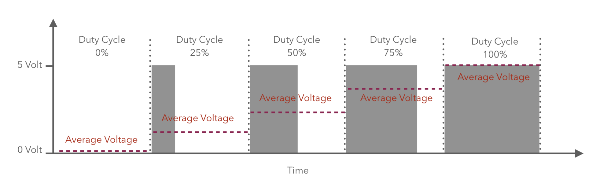
As you can make out from the diagram, the function is basically creating a pulse, the characteristics of which we are changing. The first characteristic is the frequency, the pulses generated in a second. In the code line pwm= GPIO.PWM(18,1) , we are basically telling the microcontroller to generate one pulse every second on pin number 1. In the second line, duty cycle is a percent value. It determines for how much percent of the time the pulse will be high. For the rest of the time of the pulse the output of the pin will be off. So, for the following code, the below bulleted points would be the characteristics:
pwm= GPIO.PWM(18,1)
duty_cycle = 50
- Time/width of every pulse is 1 second
- Percent of time it would on is 50%
- Percent of time it would be off is 50%
- Time it would be on is 0.5 seconds
- Time it would be off is 0.5 seconds
When we increase the frequency more than 50 hertz then it is very hard for the human eye to make out if it is actually switching on or off. Theoretically, for 50% of the time the pin will remain high, and for the rest of the time it will be low. So, if we take an average then we can easily say that the overall voltage would be half of the original. Using this method, we can modulate the voltage output of any pin as per our requirements.