
This chapter will cover the rigging and the skinning of a character. This character will be a Rat Cowboy that has been already modeled for you. Here, you will understand what the rigging process involves. We will start by placing deforming bones. After this, we will learn how to rig these bones with controllers and constraints such as IK or Copy. Then, we will skin our character so that the mesh follows the deforming bones. As a bonus, you will learn how to use shape keys in order to add some basic facial controls that will be controlled by drivers. The rig, which is covered here, will be basic, but you will have all the necessary knowledge to go further. We are going to use this rig to animate our character in the next chapter. Enjoy!
In this chapter, we will cover the following topics:
- Making a symmetric skeleton
- Using the basic bones constraints
- Rigging the eyes
- Correcting the deformation of the meshes with weight painting
- Improving the accessibility of the rig with custom shapes
- Using shape keys
We are now going to discover the process of character rigging. The point of this is to prepare objects or characters for animation in order to pose them in a simple way. For instance, when rigging a biped character, we will place virtual bones that mimic the character's real skeleton. Those bones are going to have relationships between them. In the case of a finger, for instance, we will usually add three bones that follow the phalanges. The tip bone will be the child of the mid bone, which in turn will be the child of the top bone. So when we rotate the top bone, it will automatically rotate its children. On the top of the network of the bones, we will need to add some constraints that define automation so that it is easier for the animator to pose the character. The next step is to specify to the geometry to follow the bones in some way. For instance, in the case of a character, we will tell Blender to deform the mesh according to the deformable bones. This stage is called Weight Painting in Blender and Skinning is a common term, too. However, we will not always face a case where skinning is necessary. For instance, if you have to rig a car, you will not want to deform the wheels, so you will create a bone hierarchy or constraints in order to follow the rig. The entire process could be tricky at some point, but mastering the rigging process allows you to better understand the animation process and is the reason why having a good topology is so important.
Note
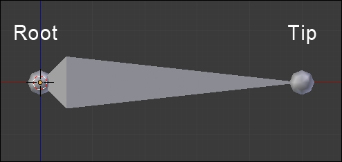
Anatomy of a bone in Blender
A bone has a root and a tip. The root corresponds to the pivot point of the bone, and the tip defines the length of the bone. Bones can have a parent-child relationship in two ways. The first method is by connecting them, so the root of the child is merged with the tip of its parent. The other method is by telling Blender that they are visually disconnected while still having a parent/child relationship. Each bone has a roll that corresponds to its orientation on itself. When manipulating an Armature object, you can be in the Edit Mode to create the network of the bones and set their relationships, or you can be in the Pose Mode where you can pose the rig as if you were posing a marionette.
Let's do the rig of the Rat Cowboy. We are not going to show the modeling process here as you already know how to model proper characters from the Alien project.
The first thing that we will need to do for our rig is place the bones that will directly deform our mesh. These are the main bones. In Blender, a rig is contained in an Armature object, so let's go!
Let's begin with the process:
- We will first be sure that our character is placed at the center of the scene with his feet on the x axis.
- Now we can add a new bone that will be placed in an Armature object (press Shift + A and select Armature | Bone).
- Next, we will enter the Edit Mode of our new Armature object, and we will place the bone in the hip location and rename it as
hips. You can rename a bone in the right panel of the 3D view in the Item subpanel. Be careful to rename just the bone and not the Armature object. - We can now start to extrude the bones of the spine. To do this, we will select the tip of the hips and extrude it (E) twice as far as the base of the neck. It's very important that you don't move these bones on the X axis. We will rename the bones as Spine01 and Spine02 respectively. From the side view, be sure that these bones are slightly bent.
- We will now extrude the left clavicle according to the Rat Cowboy's structure and rename it as Clavicle.L. The .L part is really important here because Blender will understand that this is on the left-hand side and will manage the right-hand side automatically later when mirroring the rig.
- Now, from the tip of the clavicle, we will extrude the bones of the arm. Rename the two bones as TopArm.L and Forearm.L.
- Now it's time to extrude the bone of the hand, starting from the tip of the forearm. Name this as Hand.L.
- In order to create the finger bones, we will start from a new chain and parent it back to the hand. This will allow us to have bones that are visually disconnected from their parents. To do this, we will place the 3D cursor near the base of the first finger and press Shift + A. Since you can only add bones when you are in the Edit Mode of the Armature, this will automatically create a new bone. We will orient it correctly and move its tip to the first phalange. We will extrude its tip to form the next two bones. It's important to place the bones right in the middle of the finger and on the phalanges so that the finger bends properly. Analyze the topology of the mesh to do this precisely. If you want, you can activate the Snap option (the magnet in the 3D view header) and change its mode from Increment to Volume to automatically place the bones according to the volume of the finger.
- Then we will create the chains for the other fingers and the thumb and rename them as Finger[Which finger]Top.L, Finger[Which finger]Mid.L, and Finger[Which finger]Tip.L.
- We will now need to re-parent them to the hand so, when the hand moves, the fingers follow. To do this, we will select the top bone of each finger (the root of each finger chain) and then select the hand bone (so that it is the active selection) while holding Shift, pressing Ctrl + P, and selecting Keep Offset. Keep Offset means that the bones are going to be parented but they will keeping their original positions (that is, they are not connected to their parent).
- We will now change our cursor location to the left thigh of our character and press Shift + A. We can then place the tip of this bone to the knee location. Also, check the side view and put this tip a little bit forward. We can then extrude a new bone from the knee to the ankle. Rename these bones as Thigh.L and Bottom Leg.L.
- We can then extrude the foot and the toes. Name them as Foot.L and Toes.L.
- The leg chain needs to be parented to the hips. This can be done with Ctrl + P and selecting Keep Offset. Remember to first select the child and then the parent while doing your selection for parenting.
- Now we can add the bones of the tail. We will create a chain of bones starting from the back of the Rat Cowboy to the tip of the tail where the tips and roots of each bone are placed according to the topology of the mesh. Remember to rename the bones properly from Tail01 to Tail07.
- Then we will parent Tail01 to Hips by pressing Ctrl + P and selecting Keep Offset so that the whole tail is attached to the rest of the body.
- The last bones that we will need to extrude are the neck and the head. The neck starts from the tip of the Spine01 bone and goes straight up along the Z axis. Then we will extrude the head bone from the neck tip. We will rename them as Neck and Head.
Now we will have to verify on which axis the bone will rotate. You can display the axes of the bones in the Armature tab of the Properties editor under the Display subpanel. We will need to adjust the roll of each bone (Ctrl + R in the Edit Mode) to align them along the x axis. You can test the rotations by going to the Pose Mode (Ctrl + Tab) and rotating the bones around their x local axis by pressing R and then pressing X twice. Beware, rolls are very important!
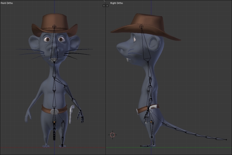
Placement of the deforming bones
Note
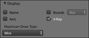
The Display options
You can find different display options for your bones in the Display subpanel in the Object Data tab of the Properties editor. A nice way to display the bones is to activate the X-Ray display mode, which allows us to see the bones through the mesh even in Solid shading mode. We can also display the axes of orientation and the name of each bone and change its shape.
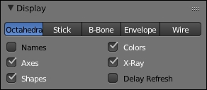
For instance, we can use the B-Bone mode that changes the bones to boxes that we can rescale with Ctrl + Alt + S. This is a nice way to display bones that are on top of each other. You can also use the Maximum Draw Type drop-down menu in order to change the shading of your selected object in the Display subpanel in the Object tab of the Properties editor.
The following image will show the placement of the deforming bones of the hand:
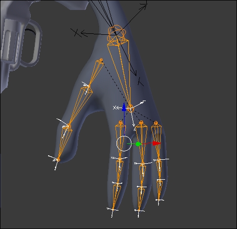
Placement of the deforming bones of the hand with a correct roll
Now that we have all the deforming bones that are needed, we are going to add some bones that will help us to control the leg and the foot in a better way.
- We will now add a bone that will be a controller for the Inverse Kinematic (IK) constraint of the leg. We add this to the ankle and align it with the floor. It's important that this bone is disconnected for now. We rename it as LegIK.L.
- Under the Bone tab of the Properties editor, we will uncheck the Deform checkbox so that our bone does not deform our geometry later.
Note
What is an IK constraint?
Usually, when you manipulate bones in the Pose Mode, you rotate each one in order to pose your object, and this method is called FK (Forward Kinematic). The role of an IK constraint is to let Blender calculate the angle between a minimum of two bones according to a target. To better understand what this does, imagine that your foot is a 3D object and you can move it where you want in space. As you can see, your thigh and lower leg will automatically bend with an appropriate angle and direction. That's the whole point of IK!

- Now we are going to tell Blender that this new bone is the target that will control the IK constraint. To do this, we will first select it in the pose mode (Ctrl + Tab) and then select the lower leg bone to make it the active bone. Now we can use the Shift + I shortcut to create a new IK constraint. As you can see, the lower leg bone turns yellow.
- Now we will change the settings of the constraint. The bone Constraints panel is located in the properties editor (a bone with a chain icon) in the Pose Mode. If we select the lower leg bone, we can see our IK constraint located here. As we've used the Shift + I shortcut, all the fields are already filled. The setting that we will change is Chain Length. We set this to two. This will tell Blender to calculate our IK constraint from the bone where the constraint is on the tip to the next bone in the leg chain.
- We can now go back to the Edit Mode (Tab) and add a new floating bone in front of the knee location. This bone will be the target of the knee. Rename it as PollTargetKnee.L.
- Back in the Pose Mode (Ctrl + Tab), we will set this new bone as the Pole Target bone for the IK constraint. We will first select the Armature object and then the bone. After this, we will adjust Pole Angle to reorient the IK constraint so that the leg points to the knee target. In our case, it's set to 90°.
- The next thing to do is to uncheck the stretch option so that the leg can't be longer than it already is.
- Now that we've rigged the leg, it's time to rig the foot. We are going to make an easy foot rig here. But note that a foot rig can be much more complex with a foot roll. In our case, we will first remove the Foot.L parentation. To do this, we go into the Edit Mode, select the parent, press Alt + P, and select Clear parent.
- Now we want to switch the direction of the bone so that its root is located at the toes. To do that, we will select the bone in the Edit Mode, press W, and select Flip Direction. Remember that a bone rotates around its root, so this will give us the ability to lift the foot up on the character's toes.
- Now we can connect the IK target to the foot bone. To do this, we will simply select the child (LegIK.L), select the parent (Foot.L), press Ctrl + P, and select Connected. So now, when we rotate the foot in the Pose Mode, the IK target is going to lift up and the IK constraint will do its job.
- The last thing that we will need to do is create a master bone that will move all our foot bones. In the Edit Mode, we will add a bone that starts from the heel to the toes and rename it as FootMaster.L. We will then parent the toes to this with the Keep Offset option. Then we will parent the foot to the toes with the Keep Offset option. As you can see, if you move the master bone in the Pose Mode, all the bones will follow this. We are done with the foot and the leg rig!

The rigging of the foot and the leg
The next important part to rig is the arm. In many rigs, you will have a method to switch between FK and IK for the arms. In our case, we are only going to use IK because it will be quite long and boring to teach how to create a proper IK/FK switch with snaps. When animating the arm with IK, you will have to animate arcs by hand, but this will allow you much more control if you don't have an FK/IK switch.
- We will create a new floating bone that will become our IK target for the arm by duplicating the bone of the hand and clearing its parent. Remember that the target of an IK switch needs to be freely movable! We will rename this bone as HandIK.L.
- Then we will set up our IK constraint by first selecting the target, then the forearm, and then pressing Shift + I. Now, we can change the chain length to two as we did for the leg.
- The next thing to do is add a poll target for the orientation of the elbow. To do this, we will create a floating bone behind the elbow of our left arm, we rename this as ElbowPollTarget.L, and we set this as the poll target of the IK constraint. Also, we will change the Poll Angle to match the correct orientation of the elbow.
- Both the target and the IK target need to have the Deform option turned off.
- The animator will only want to manage one bone for the hand. The bone that will deform the hand is not the target as it needs to be connected to the arm, so we will need to find a way to tell the hand-deforming bone to follow the IK target rotation. If this happens, the animator will only control the target for both arm placement and the hand rotation. To do this, the IK target is going to transfer its rotation to the deform bone. So, we will first select the HandIK.L bone, then the Hand.L bone, and then press Ctrl + Shift + C to open the constraint floating menu and select CopyRotation.
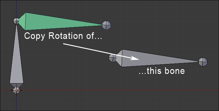
- We are now going to rig the fingers again with a Copy Rotation constraint. The motion that we want to achieve is that, when the base of the finger is rotated around the X local axis, the finger curls. To do this, we will indicate to the mid bone of the finger to copy the rotation of its parent (the top bone) and the tips to copy the rotation of its parent too (the mid bone). We will show the process for the index finger and let you do the rest for the others.
- We will select the Finger1Top.L bone, then the Finger1Mid.L bone, press Ctrl + Shift + C, and select CopyRotation. After this, we will select the Finger1Mid.L bone, then the Finger1Tip.L bone, and create a copy rotation constraint. If we rotate Finger1Top.L on the X local axis, we can see that the finger bends.
- In order to finish the hand, we will disable the Y and Z local rotations of the mid and tip bones of each finger. To disable a rotation on a particular axis, we will open the right panel of the 3D view (N) and change the rotation type from Quaternion to XYZ Euler. Then we can use the lock icon on a particular axis.

The rigging of the arm and the hand
Note
What is a Copy Rotation constraint?
As its name implies, the copy rotation constraint will tell an entity to copy the rotation of another entity. The settings of the constraint allow you to choose in which space the rotation will be. The often used spaces are World or Local.
The World space has its axes aligned with the world (you can see them in the left corner of the 3D view).
The Local space has to do with the orientation of an object. For instance, if an airplane has a certain direction, but when it rotates around its fuselage, this takes into account its orientation.
Now it's time to do the hips motion so that it is easier to control for animation. You have done a lot of work until here. Have yourself a cookie, you deserve it!
- To create our hips motion, we will duplicate the hip bone. Also, remember to uncheck the Deform option. We will rename it as HipsReverse.
- Now, we are going to flip the direction of this bone so that the hip deforming bone rotates around its tips (because the root of the hip's reverse bones will be here).
- Now you can test in the Pose Mode that, when you rotate the HipsReverse bone, the hip's deform bone rotates with it.

The rigging of the hips with the reversed bone
A rat without a tail is pretty strange, so we will take some time to rig his tail. The technique that we will show here is quite simple but very effective:
- In order to rig the tail of the Rat Cowboy, we will need to add a new bone that controls this in the Edit Mode. To do this, we will extrude the last Tail07 bone so that it is placed at the right location, and we will un-parent it with Alt + P and select Clear Parent. Rename this as TailIK.
- We will now need to create an IK constraint. We will first select the target, then the Tail07 bone (the last in the chain), and press Shift + I.
- Now in the IK constraint settings, we will change the chain length to 7 (to let the IK constraint solve the angles from the tip to the last bone of the tail chain).
- We will check the Rotation option, too. Now, as you can see, the tail is fully rigged and can be placed and rotated through the tail target:

The rigging of the tail with a chain length of 7
In order to control the head, we will only manipulate the bone of the head, so we will directly begin the rigging of the eyes. We will ensure that the eyes are two separated objects and they have their pivot points at the center to make for good rotation. In our case, we have two half spheres, so we don't waste performance with hidden geometry:
- We will select one of the eyes, and in the Edit Mode (Tab), we will select the outer edge loop. We will press Shift + S to open the Snap menu, then we will select the Cursor to Selected option, and then, in the Object Mode (Tab), we will press Ctrl + Alt + Shift + C and select Origin to 3D cursor. The pivot point must be at the right location. Do not hesitate to test this with a free rotation (R x 2) in the Object Mode. We must repeat the same process for the other eye.
- In the Object Mode, we will select the eyes and the teeth, and then we will parent them to the head bone, but not with the usual method of parenting the bones that we saw earlier. To do this, we will first select the eyes and the teeth, and then the head bone (the armature must be in the Pose Mode). We will press Ctrl + P, and we will select the Bone option.
- We now want to create a controller bone for each eye. We will select the armature, and in the Edit Mode (Tab), with the 3D Cursor in the middle of the eye, we will create a bone (Shift + A). In the Orthographic (5) left (3) view, we will move the controller bone in the front of the character. We need a small distance between the head and the bone controller. We will repeat the same process for the other eye, and we will rename them as EyeTarget.L and EyeTarget.R.
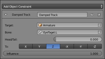
- We will set the eyes to look at their controllers with a Damped Track constraint (Properties | Constraint). We will start with the left eye. We must select the Armature as Target and EyeTarget.L as the bone. Now, we must adjust the rotation by tweaking the Z axis.

The eyes' controllers
Both the eyes must now follow the EyeTargetMaster movements. Do a test by pressing G.
In order to save time, as in the modeling or the sculpting process, it is often very useful to work with symmetry. There are three ways to do this in an armature.
The first method consists of checking the X-Axis Mirror option in the Armature Options tab in the left panel of the 3D Viewport (T) that allows us to directly create the bones in a symmetry. We must extrude the bones by pressing E while also pressing Shift. This solution doesn't copy the constraints.
The second method is efficient even if it requires some manipulations to get a perfect mirror. Until then, we will place the bones of the arms and legs on the left-hand side with all the constrains that we need and the appropriate names:
- We will select the armature in the Edit Mode, and we will align the 3D cursor at the center (Shift + S and select Cursor to Center).
- In the Header, we will put the Pivot Point options on 3D Cursor.
- Then, we will select every bone of the arm and the leg on the left-hand side.
- We will duplicate them (Shift + D), and we will mirror them by pressing S + X + 1 on the numeric keyboard. Then we will press Enter.
- In the Edit Mode, we will select the bones of the arm and the leg on the right-hand side and flip the names (Armature | Flip Names). This renames all the bones of the left-hand side with the .R termination.

Mirroring the bones with their constraints from the left to the right side
The third method is very interesting. It has been available since Blender 2.75.
Once we have placed and named all the bones with the .L termination and have all the constraints, we will select them in the Edit Mode, and then we will press W and select Symmetrize. This will automatically rename the bones of the right-hand side and the constraints will be copied.
Let's now focus on the gun for a rig.
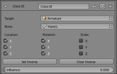
In order to easily animate the gun, we will need it to be able to follow the hand of our character when the Rat Cowboy uses it, and the gun must be able to follow the holster all the time. To do this, we will use a bone and a Child Of constraint.
Note
The Child Of constraint
This constraint allows us to make an object a parent of another object by weighting their influences. This allows the animator to animate its influence in order to change its parent. This is much better than a classical parentation. This is very useful to make an object follow different objects one after another like a character driving with one hand on the steering wheel and the other hand on the speed box. You can also combine multiple children of the constraints.
- We will begin by taking care to apply the rotation of the gun (press Ctrl + A and select Scale and Rotate).
- We will select our Armature, and in the Edit Mode, we will place the 3D Cursor at the location of the hammer; then we will create a bone (Shift + A) that follows the length of the gun. We will rename this new bone as Gun.
- We will make the gun the parent of the bone by first selecting the gun in the Object Mode, then the Gun bone in the Pose Mode, and then we will press Ctrl + P and select Bone.
- We will then modify the appearance of the bone in B-Bone (Properties | Object Data | Display | B-Bone). We will scale it to make it easier to rig (Ctrl + Alt + S).
- We will check the X-Ray option.
- We will move the gun in the holster by moving and rotating the Gun bone. You can also directly rotate the gun a little bit in order to get the best position.
- We will add two Child Of constraints to the Gun bone. We will uncheck the scale option of both the constraints.
- We will decrease the influence to 0 on both the Child Of constraints.
- With the first Child Of constraint, we will put our Armature as Target with the Hand.L bone in the bone option. We will press the Set Inverse button.
- For the second Child Of constraint, we will put the Holster object as Target, and we will press the Set Inverse button again.
Now, when we place the left hand with HandIK.L near the gun and put the influence of the first Child Of constraint at 1.000 (the influence of the second Child Of constraint must still be at 0), the gun joins the HandIK.L bone and follows it. In order to reposition the gun in the holster, it must be very near to the holster. The influence of the first Child Of constraint must be at 0, and the influence of the second one must be at 1.0 (reversed influences).
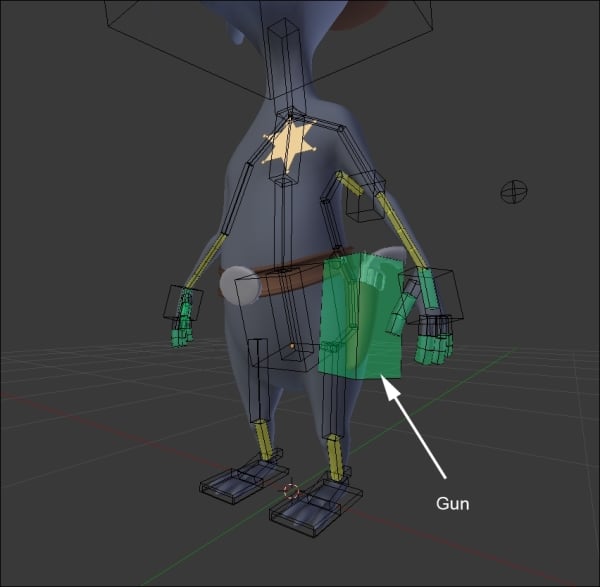
The gun bone
Now we are going to rig the holster. As you can see, it is a separate object. We will need to pin it to the belt. In this section, we won't use bones, but they are still a part of the rigging process.
- First, what we are going to do here is create an empty object that will be the parent of the holster. To create an empty object, press Shift + A and select Empty | Plain Axis.
- Now we will select the empty object, and while holding Shift, we will select the belt. We can now enter the Edit Mode of the belt and choose a vertex near the pin of the holster. We can press Ctrl + P and choose Make Vertex Parent. Now when we move the vertex, it moves the empty object!
- The last thing that we need to do is make the holster the parent of the empty object, and the trick is done! Of course, we could have made the holster object a parent of the vertex directly, but it's always nice to have an empty object in between in this kind of situation.

The rigging of the holster
The root bone is also called the master bone; it is the bone that will control the entire skeleton and is the top parent. With this, it is very convenient to place our character and animate it anywhere.
- We will select the Armature, switch in the Edit Mode (Tab), place the Pivot Point at the center of the world (press Shift + S and select Cursor to Center), and then we will add a bone (Shift + A).
- We will make this bone bigger (Ctrl + Alt + S in the B-Bone mode) because it represents the central control element of the Armature. We will flatten it by selecting and moving the tip of the bone. We will rename it as Root.
- In the Edit Mode, we will select the IK bone controllers of the hands, feet, tail, EyeTargetMaster that controls the Eyes, Hips, and Pole Targets at the location of the knees and the elbows; finally, we will select the master bone (so that it is the active selection).
- We will make them parents (press Ctrl + P and select Keep Offset).
- Remember to uncheck the Deform option (Properties | Bone | Deform).
- You can see all the bones follow when you move the Root Bone.

The root bone at the center of the world
Placing the deforming bones
The first thing that we will need to do for our rig is place the bones that will directly deform our mesh. These are the main bones. In Blender, a rig is contained in an Armature object, so let's go!
Let's begin with the process:
- We will first be sure that our character is placed at the center of the scene with his feet on the x axis.
- Now we can add a new bone that will be placed in an Armature object (press Shift + A and select Armature | Bone).
- Next, we will enter the Edit Mode of our new Armature object, and we will place the bone in the hip location and rename it as
hips. You can rename a bone in the right panel of the 3D view in the Item subpanel. Be careful to rename just the bone and not the Armature object. - We can now start to extrude the bones of the spine. To do this, we will select the tip of the hips and extrude it (E) twice as far as the base of the neck. It's very important that you don't move these bones on the X axis. We will rename the bones as Spine01 and Spine02 respectively. From the side view, be sure that these bones are slightly bent.
- We will now extrude the left clavicle according to the Rat Cowboy's structure and rename it as Clavicle.L. The .L part is really important here because Blender will understand that this is on the left-hand side and will manage the right-hand side automatically later when mirroring the rig.
- Now, from the tip of the clavicle, we will extrude the bones of the arm. Rename the two bones as TopArm.L and Forearm.L.
- Now it's time to extrude the bone of the hand, starting from the tip of the forearm. Name this as Hand.L.
- In order to create the finger bones, we will start from a new chain and parent it back to the hand. This will allow us to have bones that are visually disconnected from their parents. To do this, we will place the 3D cursor near the base of the first finger and press Shift + A. Since you can only add bones when you are in the Edit Mode of the Armature, this will automatically create a new bone. We will orient it correctly and move its tip to the first phalange. We will extrude its tip to form the next two bones. It's important to place the bones right in the middle of the finger and on the phalanges so that the finger bends properly. Analyze the topology of the mesh to do this precisely. If you want, you can activate the Snap option (the magnet in the 3D view header) and change its mode from Increment to Volume to automatically place the bones according to the volume of the finger.
- Then we will create the chains for the other fingers and the thumb and rename them as Finger[Which finger]Top.L, Finger[Which finger]Mid.L, and Finger[Which finger]Tip.L.
- We will now need to re-parent them to the hand so, when the hand moves, the fingers follow. To do this, we will select the top bone of each finger (the root of each finger chain) and then select the hand bone (so that it is the active selection) while holding Shift, pressing Ctrl + P, and selecting Keep Offset. Keep Offset means that the bones are going to be parented but they will keeping their original positions (that is, they are not connected to their parent).
- We will now change our cursor location to the left thigh of our character and press Shift + A. We can then place the tip of this bone to the knee location. Also, check the side view and put this tip a little bit forward. We can then extrude a new bone from the knee to the ankle. Rename these bones as Thigh.L and Bottom Leg.L.
- We can then extrude the foot and the toes. Name them as Foot.L and Toes.L.
- The leg chain needs to be parented to the hips. This can be done with Ctrl + P and selecting Keep Offset. Remember to first select the child and then the parent while doing your selection for parenting.
- Now we can add the bones of the tail. We will create a chain of bones starting from the back of the Rat Cowboy to the tip of the tail where the tips and roots of each bone are placed according to the topology of the mesh. Remember to rename the bones properly from Tail01 to Tail07.
- Then we will parent Tail01 to Hips by pressing Ctrl + P and selecting Keep Offset so that the whole tail is attached to the rest of the body.
- The last bones that we will need to extrude are the neck and the head. The neck starts from the tip of the Spine01 bone and goes straight up along the Z axis. Then we will extrude the head bone from the neck tip. We will rename them as Neck and Head.
Now we will have to verify on which axis the bone will rotate. You can display the axes of the bones in the Armature tab of the Properties editor under the Display subpanel. We will need to adjust the roll of each bone (Ctrl + R in the Edit Mode) to align them along the x axis. You can test the rotations by going to the Pose Mode (Ctrl + Tab) and rotating the bones around their x local axis by pressing R and then pressing X twice. Beware, rolls are very important!
Placement of the deforming bones
Note
The Display options
You can find different display options for your bones in the Display subpanel in the Object Data tab of the Properties editor. A nice way to display the bones is to activate the X-Ray display mode, which allows us to see the bones through the mesh even in Solid shading mode. We can also display the axes of orientation and the name of each bone and change its shape.
For instance, we can use the B-Bone mode that changes the bones to boxes that we can rescale with Ctrl + Alt + S. This is a nice way to display bones that are on top of each other. You can also use the Maximum Draw Type drop-down menu in order to change the shading of your selected object in the Display subpanel in the Object tab of the Properties editor.
The following image will show the placement of the deforming bones of the hand:
Placement of the deforming bones of the hand with a correct roll
Now that we have all the deforming bones that are needed, we are going to add some bones that will help us to control the leg and the foot in a better way.
- We will now add a bone that will be a controller for the Inverse Kinematic (IK) constraint of the leg. We add this to the ankle and align it with the floor. It's important that this bone is disconnected for now. We rename it as LegIK.L.
- Under the Bone tab of the Properties editor, we will uncheck the Deform checkbox so that our bone does not deform our geometry later.
Note
What is an IK constraint?
Usually, when you manipulate bones in the Pose Mode, you rotate each one in order to pose your object, and this method is called FK (Forward Kinematic). The role of an IK constraint is to let Blender calculate the angle between a minimum of two bones according to a target. To better understand what this does, imagine that your foot is a 3D object and you can move it where you want in space. As you can see, your thigh and lower leg will automatically bend with an appropriate angle and direction. That's the whole point of IK!
- Now we are going to tell Blender that this new bone is the target that will control the IK constraint. To do this, we will first select it in the pose mode (Ctrl + Tab) and then select the lower leg bone to make it the active bone. Now we can use the Shift + I shortcut to create a new IK constraint. As you can see, the lower leg bone turns yellow.
- Now we will change the settings of the constraint. The bone Constraints panel is located in the properties editor (a bone with a chain icon) in the Pose Mode. If we select the lower leg bone, we can see our IK constraint located here. As we've used the Shift + I shortcut, all the fields are already filled. The setting that we will change is Chain Length. We set this to two. This will tell Blender to calculate our IK constraint from the bone where the constraint is on the tip to the next bone in the leg chain.
- We can now go back to the Edit Mode (Tab) and add a new floating bone in front of the knee location. This bone will be the target of the knee. Rename it as PollTargetKnee.L.
- Back in the Pose Mode (Ctrl + Tab), we will set this new bone as the Pole Target bone for the IK constraint. We will first select the Armature object and then the bone. After this, we will adjust Pole Angle to reorient the IK constraint so that the leg points to the knee target. In our case, it's set to 90°.
- The next thing to do is to uncheck the stretch option so that the leg can't be longer than it already is.
- Now that we've rigged the leg, it's time to rig the foot. We are going to make an easy foot rig here. But note that a foot rig can be much more complex with a foot roll. In our case, we will first remove the Foot.L parentation. To do this, we go into the Edit Mode, select the parent, press Alt + P, and select Clear parent.
- Now we want to switch the direction of the bone so that its root is located at the toes. To do that, we will select the bone in the Edit Mode, press W, and select Flip Direction. Remember that a bone rotates around its root, so this will give us the ability to lift the foot up on the character's toes.
- Now we can connect the IK target to the foot bone. To do this, we will simply select the child (LegIK.L), select the parent (Foot.L), press Ctrl + P, and select Connected. So now, when we rotate the foot in the Pose Mode, the IK target is going to lift up and the IK constraint will do its job.
- The last thing that we will need to do is create a master bone that will move all our foot bones. In the Edit Mode, we will add a bone that starts from the heel to the toes and rename it as FootMaster.L. We will then parent the toes to this with the Keep Offset option. Then we will parent the foot to the toes with the Keep Offset option. As you can see, if you move the master bone in the Pose Mode, all the bones will follow this. We are done with the foot and the leg rig!
The rigging of the foot and the leg
The next important part to rig is the arm. In many rigs, you will have a method to switch between FK and IK for the arms. In our case, we are only going to use IK because it will be quite long and boring to teach how to create a proper IK/FK switch with snaps. When animating the arm with IK, you will have to animate arcs by hand, but this will allow you much more control if you don't have an FK/IK switch.
- We will create a new floating bone that will become our IK target for the arm by duplicating the bone of the hand and clearing its parent. Remember that the target of an IK switch needs to be freely movable! We will rename this bone as HandIK.L.
- Then we will set up our IK constraint by first selecting the target, then the forearm, and then pressing Shift + I. Now, we can change the chain length to two as we did for the leg.
- The next thing to do is add a poll target for the orientation of the elbow. To do this, we will create a floating bone behind the elbow of our left arm, we rename this as ElbowPollTarget.L, and we set this as the poll target of the IK constraint. Also, we will change the Poll Angle to match the correct orientation of the elbow.
- Both the target and the IK target need to have the Deform option turned off.
- The animator will only want to manage one bone for the hand. The bone that will deform the hand is not the target as it needs to be connected to the arm, so we will need to find a way to tell the hand-deforming bone to follow the IK target rotation. If this happens, the animator will only control the target for both arm placement and the hand rotation. To do this, the IK target is going to transfer its rotation to the deform bone. So, we will first select the HandIK.L bone, then the Hand.L bone, and then press Ctrl + Shift + C to open the constraint floating menu and select CopyRotation.
- We are now going to rig the fingers again with a Copy Rotation constraint. The motion that we want to achieve is that, when the base of the finger is rotated around the X local axis, the finger curls. To do this, we will indicate to the mid bone of the finger to copy the rotation of its parent (the top bone) and the tips to copy the rotation of its parent too (the mid bone). We will show the process for the index finger and let you do the rest for the others.
- We will select the Finger1Top.L bone, then the Finger1Mid.L bone, press Ctrl + Shift + C, and select CopyRotation. After this, we will select the Finger1Mid.L bone, then the Finger1Tip.L bone, and create a copy rotation constraint. If we rotate Finger1Top.L on the X local axis, we can see that the finger bends.
- In order to finish the hand, we will disable the Y and Z local rotations of the mid and tip bones of each finger. To disable a rotation on a particular axis, we will open the right panel of the 3D view (N) and change the rotation type from Quaternion to XYZ Euler. Then we can use the lock icon on a particular axis.
The rigging of the arm and the hand
Note
What is a Copy Rotation constraint?
As its name implies, the copy rotation constraint will tell an entity to copy the rotation of another entity. The settings of the constraint allow you to choose in which space the rotation will be. The often used spaces are World or Local.
The World space has its axes aligned with the world (you can see them in the left corner of the 3D view).
The Local space has to do with the orientation of an object. For instance, if an airplane has a certain direction, but when it rotates around its fuselage, this takes into account its orientation.
Now it's time to do the hips motion so that it is easier to control for animation. You have done a lot of work until here. Have yourself a cookie, you deserve it!
- To create our hips motion, we will duplicate the hip bone. Also, remember to uncheck the Deform option. We will rename it as HipsReverse.
- Now, we are going to flip the direction of this bone so that the hip deforming bone rotates around its tips (because the root of the hip's reverse bones will be here).
- Now you can test in the Pose Mode that, when you rotate the HipsReverse bone, the hip's deform bone rotates with it.
The rigging of the hips with the reversed bone
A rat without a tail is pretty strange, so we will take some time to rig his tail. The technique that we will show here is quite simple but very effective:
- In order to rig the tail of the Rat Cowboy, we will need to add a new bone that controls this in the Edit Mode. To do this, we will extrude the last Tail07 bone so that it is placed at the right location, and we will un-parent it with Alt + P and select Clear Parent. Rename this as TailIK.
- We will now need to create an IK constraint. We will first select the target, then the Tail07 bone (the last in the chain), and press Shift + I.
- Now in the IK constraint settings, we will change the chain length to 7 (to let the IK constraint solve the angles from the tip to the last bone of the tail chain).
- We will check the Rotation option, too. Now, as you can see, the tail is fully rigged and can be placed and rotated through the tail target:
The rigging of the tail with a chain length of 7
In order to control the head, we will only manipulate the bone of the head, so we will directly begin the rigging of the eyes. We will ensure that the eyes are two separated objects and they have their pivot points at the center to make for good rotation. In our case, we have two half spheres, so we don't waste performance with hidden geometry:
- We will select one of the eyes, and in the Edit Mode (Tab), we will select the outer edge loop. We will press Shift + S to open the Snap menu, then we will select the Cursor to Selected option, and then, in the Object Mode (Tab), we will press Ctrl + Alt + Shift + C and select Origin to 3D cursor. The pivot point must be at the right location. Do not hesitate to test this with a free rotation (R x 2) in the Object Mode. We must repeat the same process for the other eye.
- In the Object Mode, we will select the eyes and the teeth, and then we will parent them to the head bone, but not with the usual method of parenting the bones that we saw earlier. To do this, we will first select the eyes and the teeth, and then the head bone (the armature must be in the Pose Mode). We will press Ctrl + P, and we will select the Bone option.
- We now want to create a controller bone for each eye. We will select the armature, and in the Edit Mode (Tab), with the 3D Cursor in the middle of the eye, we will create a bone (Shift + A). In the Orthographic (5) left (3) view, we will move the controller bone in the front of the character. We need a small distance between the head and the bone controller. We will repeat the same process for the other eye, and we will rename them as EyeTarget.L and EyeTarget.R.
- We will set the eyes to look at their controllers with a Damped Track constraint (Properties | Constraint). We will start with the left eye. We must select the Armature as Target and EyeTarget.L as the bone. Now, we must adjust the rotation by tweaking the Z axis.
The eyes' controllers
Both the eyes must now follow the EyeTargetMaster movements. Do a test by pressing G.
In order to save time, as in the modeling or the sculpting process, it is often very useful to work with symmetry. There are three ways to do this in an armature.
The first method consists of checking the X-Axis Mirror option in the Armature Options tab in the left panel of the 3D Viewport (T) that allows us to directly create the bones in a symmetry. We must extrude the bones by pressing E while also pressing Shift. This solution doesn't copy the constraints.
The second method is efficient even if it requires some manipulations to get a perfect mirror. Until then, we will place the bones of the arms and legs on the left-hand side with all the constrains that we need and the appropriate names:
- We will select the armature in the Edit Mode, and we will align the 3D cursor at the center (Shift + S and select Cursor to Center).
- In the Header, we will put the Pivot Point options on 3D Cursor.
- Then, we will select every bone of the arm and the leg on the left-hand side.
- We will duplicate them (Shift + D), and we will mirror them by pressing S + X + 1 on the numeric keyboard. Then we will press Enter.
- In the Edit Mode, we will select the bones of the arm and the leg on the right-hand side and flip the names (Armature | Flip Names). This renames all the bones of the left-hand side with the .R termination.
Mirroring the bones with their constraints from the left to the right side
The third method is very interesting. It has been available since Blender 2.75.
Once we have placed and named all the bones with the .L termination and have all the constraints, we will select them in the Edit Mode, and then we will press W and select Symmetrize. This will automatically rename the bones of the right-hand side and the constraints will be copied.
Let's now focus on the gun for a rig.
In order to easily animate the gun, we will need it to be able to follow the hand of our character when the Rat Cowboy uses it, and the gun must be able to follow the holster all the time. To do this, we will use a bone and a Child Of constraint.
Note
The Child Of constraint
This constraint allows us to make an object a parent of another object by weighting their influences. This allows the animator to animate its influence in order to change its parent. This is much better than a classical parentation. This is very useful to make an object follow different objects one after another like a character driving with one hand on the steering wheel and the other hand on the speed box. You can also combine multiple children of the constraints.
- We will begin by taking care to apply the rotation of the gun (press Ctrl + A and select Scale and Rotate).
- We will select our Armature, and in the Edit Mode, we will place the 3D Cursor at the location of the hammer; then we will create a bone (Shift + A) that follows the length of the gun. We will rename this new bone as Gun.
- We will make the gun the parent of the bone by first selecting the gun in the Object Mode, then the Gun bone in the Pose Mode, and then we will press Ctrl + P and select Bone.
- We will then modify the appearance of the bone in B-Bone (Properties | Object Data | Display | B-Bone). We will scale it to make it easier to rig (Ctrl + Alt + S).
- We will check the X-Ray option.
- We will move the gun in the holster by moving and rotating the Gun bone. You can also directly rotate the gun a little bit in order to get the best position.
- We will add two Child Of constraints to the Gun bone. We will uncheck the scale option of both the constraints.
- We will decrease the influence to 0 on both the Child Of constraints.
- With the first Child Of constraint, we will put our Armature as Target with the Hand.L bone in the bone option. We will press the Set Inverse button.
- For the second Child Of constraint, we will put the Holster object as Target, and we will press the Set Inverse button again.
Now, when we place the left hand with HandIK.L near the gun and put the influence of the first Child Of constraint at 1.000 (the influence of the second Child Of constraint must still be at 0), the gun joins the HandIK.L bone and follows it. In order to reposition the gun in the holster, it must be very near to the holster. The influence of the first Child Of constraint must be at 0, and the influence of the second one must be at 1.0 (reversed influences).
The gun bone
Now we are going to rig the holster. As you can see, it is a separate object. We will need to pin it to the belt. In this section, we won't use bones, but they are still a part of the rigging process.
- First, what we are going to do here is create an empty object that will be the parent of the holster. To create an empty object, press Shift + A and select Empty | Plain Axis.
- Now we will select the empty object, and while holding Shift, we will select the belt. We can now enter the Edit Mode of the belt and choose a vertex near the pin of the holster. We can press Ctrl + P and choose Make Vertex Parent. Now when we move the vertex, it moves the empty object!
- The last thing that we need to do is make the holster the parent of the empty object, and the trick is done! Of course, we could have made the holster object a parent of the vertex directly, but it's always nice to have an empty object in between in this kind of situation.
The rigging of the holster
The root bone is also called the master bone; it is the bone that will control the entire skeleton and is the top parent. With this, it is very convenient to place our character and animate it anywhere.
- We will select the Armature, switch in the Edit Mode (Tab), place the Pivot Point at the center of the world (press Shift + S and select Cursor to Center), and then we will add a bone (Shift + A).
- We will make this bone bigger (Ctrl + Alt + S in the B-Bone mode) because it represents the central control element of the Armature. We will flatten it by selecting and moving the tip of the bone. We will rename it as Root.
- In the Edit Mode, we will select the IK bone controllers of the hands, feet, tail, EyeTargetMaster that controls the Eyes, Hips, and Pole Targets at the location of the knees and the elbows; finally, we will select the master bone (so that it is the active selection).
- We will make them parents (press Ctrl + P and select Keep Offset).
- Remember to uncheck the Deform option (Properties | Bone | Deform).
- You can see all the bones follow when you move the Root Bone.
The root bone at the center of the world
The leg and the foot
Now that we have all the deforming bones that are needed, we are going to add some bones that will help us to control the leg and the foot in a better way.
- We will now add a bone that will be a controller for the Inverse Kinematic (IK) constraint of the leg. We add this to the ankle and align it with the floor. It's important that this bone is disconnected for now. We rename it as LegIK.L.
- Under the Bone tab of the Properties editor, we will uncheck the Deform checkbox so that our bone does not deform our geometry later.
Note
What is an IK constraint?
Usually, when you manipulate bones in the Pose Mode, you rotate each one in order to pose your object, and this method is called FK (Forward Kinematic). The role of an IK constraint is to let Blender calculate the angle between a minimum of two bones according to a target. To better understand what this does, imagine that your foot is a 3D object and you can move it where you want in space. As you can see, your thigh and lower leg will automatically bend with an appropriate angle and direction. That's the whole point of IK!
- Now we are going to tell Blender that this new bone is the target that will control the IK constraint. To do this, we will first select it in the pose mode (Ctrl + Tab) and then select the lower leg bone to make it the active bone. Now we can use the Shift + I shortcut to create a new IK constraint. As you can see, the lower leg bone turns yellow.
- Now we will change the settings of the constraint. The bone Constraints panel is located in the properties editor (a bone with a chain icon) in the Pose Mode. If we select the lower leg bone, we can see our IK constraint located here. As we've used the Shift + I shortcut, all the fields are already filled. The setting that we will change is Chain Length. We set this to two. This will tell Blender to calculate our IK constraint from the bone where the constraint is on the tip to the next bone in the leg chain.
- We can now go back to the Edit Mode (Tab) and add a new floating bone in front of the knee location. This bone will be the target of the knee. Rename it as PollTargetKnee.L.
- Back in the Pose Mode (Ctrl + Tab), we will set this new bone as the Pole Target bone for the IK constraint. We will first select the Armature object and then the bone. After this, we will adjust Pole Angle to reorient the IK constraint so that the leg points to the knee target. In our case, it's set to 90°.
- The next thing to do is to uncheck the stretch option so that the leg can't be longer than it already is.
- Now that we've rigged the leg, it's time to rig the foot. We are going to make an easy foot rig here. But note that a foot rig can be much more complex with a foot roll. In our case, we will first remove the Foot.L parentation. To do this, we go into the Edit Mode, select the parent, press Alt + P, and select Clear parent.
- Now we want to switch the direction of the bone so that its root is located at the toes. To do that, we will select the bone in the Edit Mode, press W, and select Flip Direction. Remember that a bone rotates around its root, so this will give us the ability to lift the foot up on the character's toes.
- Now we can connect the IK target to the foot bone. To do this, we will simply select the child (LegIK.L), select the parent (Foot.L), press Ctrl + P, and select Connected. So now, when we rotate the foot in the Pose Mode, the IK target is going to lift up and the IK constraint will do its job.
- The last thing that we will need to do is create a master bone that will move all our foot bones. In the Edit Mode, we will add a bone that starts from the heel to the toes and rename it as FootMaster.L. We will then parent the toes to this with the Keep Offset option. Then we will parent the foot to the toes with the Keep Offset option. As you can see, if you move the master bone in the Pose Mode, all the bones will follow this. We are done with the foot and the leg rig!
The rigging of the foot and the leg
The next important part to rig is the arm. In many rigs, you will have a method to switch between FK and IK for the arms. In our case, we are only going to use IK because it will be quite long and boring to teach how to create a proper IK/FK switch with snaps. When animating the arm with IK, you will have to animate arcs by hand, but this will allow you much more control if you don't have an FK/IK switch.
- We will create a new floating bone that will become our IK target for the arm by duplicating the bone of the hand and clearing its parent. Remember that the target of an IK switch needs to be freely movable! We will rename this bone as HandIK.L.
- Then we will set up our IK constraint by first selecting the target, then the forearm, and then pressing Shift + I. Now, we can change the chain length to two as we did for the leg.
- The next thing to do is add a poll target for the orientation of the elbow. To do this, we will create a floating bone behind the elbow of our left arm, we rename this as ElbowPollTarget.L, and we set this as the poll target of the IK constraint. Also, we will change the Poll Angle to match the correct orientation of the elbow.
- Both the target and the IK target need to have the Deform option turned off.
- The animator will only want to manage one bone for the hand. The bone that will deform the hand is not the target as it needs to be connected to the arm, so we will need to find a way to tell the hand-deforming bone to follow the IK target rotation. If this happens, the animator will only control the target for both arm placement and the hand rotation. To do this, the IK target is going to transfer its rotation to the deform bone. So, we will first select the HandIK.L bone, then the Hand.L bone, and then press Ctrl + Shift + C to open the constraint floating menu and select CopyRotation.
- We are now going to rig the fingers again with a Copy Rotation constraint. The motion that we want to achieve is that, when the base of the finger is rotated around the X local axis, the finger curls. To do this, we will indicate to the mid bone of the finger to copy the rotation of its parent (the top bone) and the tips to copy the rotation of its parent too (the mid bone). We will show the process for the index finger and let you do the rest for the others.
- We will select the Finger1Top.L bone, then the Finger1Mid.L bone, press Ctrl + Shift + C, and select CopyRotation. After this, we will select the Finger1Mid.L bone, then the Finger1Tip.L bone, and create a copy rotation constraint. If we rotate Finger1Top.L on the X local axis, we can see that the finger bends.
- In order to finish the hand, we will disable the Y and Z local rotations of the mid and tip bones of each finger. To disable a rotation on a particular axis, we will open the right panel of the 3D view (N) and change the rotation type from Quaternion to XYZ Euler. Then we can use the lock icon on a particular axis.
The rigging of the arm and the hand
Note
What is a Copy Rotation constraint?
As its name implies, the copy rotation constraint will tell an entity to copy the rotation of another entity. The settings of the constraint allow you to choose in which space the rotation will be. The often used spaces are World or Local.
The World space has its axes aligned with the world (you can see them in the left corner of the 3D view).
The Local space has to do with the orientation of an object. For instance, if an airplane has a certain direction, but when it rotates around its fuselage, this takes into account its orientation.
Now it's time to do the hips motion so that it is easier to control for animation. You have done a lot of work until here. Have yourself a cookie, you deserve it!
- To create our hips motion, we will duplicate the hip bone. Also, remember to uncheck the Deform option. We will rename it as HipsReverse.
- Now, we are going to flip the direction of this bone so that the hip deforming bone rotates around its tips (because the root of the hip's reverse bones will be here).
- Now you can test in the Pose Mode that, when you rotate the HipsReverse bone, the hip's deform bone rotates with it.
The rigging of the hips with the reversed bone
A rat without a tail is pretty strange, so we will take some time to rig his tail. The technique that we will show here is quite simple but very effective:
- In order to rig the tail of the Rat Cowboy, we will need to add a new bone that controls this in the Edit Mode. To do this, we will extrude the last Tail07 bone so that it is placed at the right location, and we will un-parent it with Alt + P and select Clear Parent. Rename this as TailIK.
- We will now need to create an IK constraint. We will first select the target, then the Tail07 bone (the last in the chain), and press Shift + I.
- Now in the IK constraint settings, we will change the chain length to 7 (to let the IK constraint solve the angles from the tip to the last bone of the tail chain).
- We will check the Rotation option, too. Now, as you can see, the tail is fully rigged and can be placed and rotated through the tail target:
The rigging of the tail with a chain length of 7
In order to control the head, we will only manipulate the bone of the head, so we will directly begin the rigging of the eyes. We will ensure that the eyes are two separated objects and they have their pivot points at the center to make for good rotation. In our case, we have two half spheres, so we don't waste performance with hidden geometry:
- We will select one of the eyes, and in the Edit Mode (Tab), we will select the outer edge loop. We will press Shift + S to open the Snap menu, then we will select the Cursor to Selected option, and then, in the Object Mode (Tab), we will press Ctrl + Alt + Shift + C and select Origin to 3D cursor. The pivot point must be at the right location. Do not hesitate to test this with a free rotation (R x 2) in the Object Mode. We must repeat the same process for the other eye.
- In the Object Mode, we will select the eyes and the teeth, and then we will parent them to the head bone, but not with the usual method of parenting the bones that we saw earlier. To do this, we will first select the eyes and the teeth, and then the head bone (the armature must be in the Pose Mode). We will press Ctrl + P, and we will select the Bone option.
- We now want to create a controller bone for each eye. We will select the armature, and in the Edit Mode (Tab), with the 3D Cursor in the middle of the eye, we will create a bone (Shift + A). In the Orthographic (5) left (3) view, we will move the controller bone in the front of the character. We need a small distance between the head and the bone controller. We will repeat the same process for the other eye, and we will rename them as EyeTarget.L and EyeTarget.R.
- We will set the eyes to look at their controllers with a Damped Track constraint (Properties | Constraint). We will start with the left eye. We must select the Armature as Target and EyeTarget.L as the bone. Now, we must adjust the rotation by tweaking the Z axis.
The eyes' controllers
Both the eyes must now follow the EyeTargetMaster movements. Do a test by pressing G.
In order to save time, as in the modeling or the sculpting process, it is often very useful to work with symmetry. There are three ways to do this in an armature.
The first method consists of checking the X-Axis Mirror option in the Armature Options tab in the left panel of the 3D Viewport (T) that allows us to directly create the bones in a symmetry. We must extrude the bones by pressing E while also pressing Shift. This solution doesn't copy the constraints.
The second method is efficient even if it requires some manipulations to get a perfect mirror. Until then, we will place the bones of the arms and legs on the left-hand side with all the constrains that we need and the appropriate names:
- We will select the armature in the Edit Mode, and we will align the 3D cursor at the center (Shift + S and select Cursor to Center).
- In the Header, we will put the Pivot Point options on 3D Cursor.
- Then, we will select every bone of the arm and the leg on the left-hand side.
- We will duplicate them (Shift + D), and we will mirror them by pressing S + X + 1 on the numeric keyboard. Then we will press Enter.
- In the Edit Mode, we will select the bones of the arm and the leg on the right-hand side and flip the names (Armature | Flip Names). This renames all the bones of the left-hand side with the .R termination.
Mirroring the bones with their constraints from the left to the right side
The third method is very interesting. It has been available since Blender 2.75.
Once we have placed and named all the bones with the .L termination and have all the constraints, we will select them in the Edit Mode, and then we will press W and select Symmetrize. This will automatically rename the bones of the right-hand side and the constraints will be copied.
Let's now focus on the gun for a rig.
In order to easily animate the gun, we will need it to be able to follow the hand of our character when the Rat Cowboy uses it, and the gun must be able to follow the holster all the time. To do this, we will use a bone and a Child Of constraint.
Note
The Child Of constraint
This constraint allows us to make an object a parent of another object by weighting their influences. This allows the animator to animate its influence in order to change its parent. This is much better than a classical parentation. This is very useful to make an object follow different objects one after another like a character driving with one hand on the steering wheel and the other hand on the speed box. You can also combine multiple children of the constraints.
- We will begin by taking care to apply the rotation of the gun (press Ctrl + A and select Scale and Rotate).
- We will select our Armature, and in the Edit Mode, we will place the 3D Cursor at the location of the hammer; then we will create a bone (Shift + A) that follows the length of the gun. We will rename this new bone as Gun.
- We will make the gun the parent of the bone by first selecting the gun in the Object Mode, then the Gun bone in the Pose Mode, and then we will press Ctrl + P and select Bone.
- We will then modify the appearance of the bone in B-Bone (Properties | Object Data | Display | B-Bone). We will scale it to make it easier to rig (Ctrl + Alt + S).
- We will check the X-Ray option.
- We will move the gun in the holster by moving and rotating the Gun bone. You can also directly rotate the gun a little bit in order to get the best position.
- We will add two Child Of constraints to the Gun bone. We will uncheck the scale option of both the constraints.
- We will decrease the influence to 0 on both the Child Of constraints.
- With the first Child Of constraint, we will put our Armature as Target with the Hand.L bone in the bone option. We will press the Set Inverse button.
- For the second Child Of constraint, we will put the Holster object as Target, and we will press the Set Inverse button again.
Now, when we place the left hand with HandIK.L near the gun and put the influence of the first Child Of constraint at 1.000 (the influence of the second Child Of constraint must still be at 0), the gun joins the HandIK.L bone and follows it. In order to reposition the gun in the holster, it must be very near to the holster. The influence of the first Child Of constraint must be at 0, and the influence of the second one must be at 1.0 (reversed influences).
The gun bone
Now we are going to rig the holster. As you can see, it is a separate object. We will need to pin it to the belt. In this section, we won't use bones, but they are still a part of the rigging process.
- First, what we are going to do here is create an empty object that will be the parent of the holster. To create an empty object, press Shift + A and select Empty | Plain Axis.
- Now we will select the empty object, and while holding Shift, we will select the belt. We can now enter the Edit Mode of the belt and choose a vertex near the pin of the holster. We can press Ctrl + P and choose Make Vertex Parent. Now when we move the vertex, it moves the empty object!
- The last thing that we need to do is make the holster the parent of the empty object, and the trick is done! Of course, we could have made the holster object a parent of the vertex directly, but it's always nice to have an empty object in between in this kind of situation.
The rigging of the holster
The root bone is also called the master bone; it is the bone that will control the entire skeleton and is the top parent. With this, it is very convenient to place our character and animate it anywhere.
- We will select the Armature, switch in the Edit Mode (Tab), place the Pivot Point at the center of the world (press Shift + S and select Cursor to Center), and then we will add a bone (Shift + A).
- We will make this bone bigger (Ctrl + Alt + S in the B-Bone mode) because it represents the central control element of the Armature. We will flatten it by selecting and moving the tip of the bone. We will rename it as Root.
- In the Edit Mode, we will select the IK bone controllers of the hands, feet, tail, EyeTargetMaster that controls the Eyes, Hips, and Pole Targets at the location of the knees and the elbows; finally, we will select the master bone (so that it is the active selection).
- We will make them parents (press Ctrl + P and select Keep Offset).
- Remember to uncheck the Deform option (Properties | Bone | Deform).
- You can see all the bones follow when you move the Root Bone.
The root bone at the center of the world
The arm and the hand
The next important part to rig is the arm. In many rigs, you will have a method to switch between FK and IK for the arms. In our case, we are only going to use IK because it will be quite long and boring to teach how to create a proper IK/FK switch with snaps. When animating the arm with IK, you will have to animate arcs by hand, but this will allow you much more control if you don't have an FK/IK switch.
- We will create a new floating bone that will become our IK target for the arm by duplicating the bone of the hand and clearing its parent. Remember that the target of an IK switch needs to be freely movable! We will rename this bone as HandIK.L.
- Then we will set up our IK constraint by first selecting the target, then the forearm, and then pressing Shift + I. Now, we can change the chain length to two as we did for the leg.
- The next thing to do is add a poll target for the orientation of the elbow. To do this, we will create a floating bone behind the elbow of our left arm, we rename this as ElbowPollTarget.L, and we set this as the poll target of the IK constraint. Also, we will change the Poll Angle to match the correct orientation of the elbow.
- Both the target and the IK target need to have the Deform option turned off.
- The animator will only want to manage one bone for the hand. The bone that will deform the hand is not the target as it needs to be connected to the arm, so we will need to find a way to tell the hand-deforming bone to follow the IK target rotation. If this happens, the animator will only control the target for both arm placement and the hand rotation. To do this, the IK target is going to transfer its rotation to the deform bone. So, we will first select the HandIK.L bone, then the Hand.L bone, and then press Ctrl + Shift + C to open the constraint floating menu and select CopyRotation.
- We are now going to rig the fingers again with a Copy Rotation constraint. The motion that we want to achieve is that, when the base of the finger is rotated around the X local axis, the finger curls. To do this, we will indicate to the mid bone of the finger to copy the rotation of its parent (the top bone) and the tips to copy the rotation of its parent too (the mid bone). We will show the process for the index finger and let you do the rest for the others.
- We will select the Finger1Top.L bone, then the Finger1Mid.L bone, press Ctrl + Shift + C, and select CopyRotation. After this, we will select the Finger1Mid.L bone, then the Finger1Tip.L bone, and create a copy rotation constraint. If we rotate Finger1Top.L on the X local axis, we can see that the finger bends.
- In order to finish the hand, we will disable the Y and Z local rotations of the mid and tip bones of each finger. To disable a rotation on a particular axis, we will open the right panel of the 3D view (N) and change the rotation type from Quaternion to XYZ Euler. Then we can use the lock icon on a particular axis.
The rigging of the arm and the hand
Note
What is a Copy Rotation constraint?
As its name implies, the copy rotation constraint will tell an entity to copy the rotation of another entity. The settings of the constraint allow you to choose in which space the rotation will be. The often used spaces are World or Local.
The World space has its axes aligned with the world (you can see them in the left corner of the 3D view).
The Local space has to do with the orientation of an object. For instance, if an airplane has a certain direction, but when it rotates around its fuselage, this takes into account its orientation.
Now it's time to do the hips motion so that it is easier to control for animation. You have done a lot of work until here. Have yourself a cookie, you deserve it!
- To create our hips motion, we will duplicate the hip bone. Also, remember to uncheck the Deform option. We will rename it as HipsReverse.
- Now, we are going to flip the direction of this bone so that the hip deforming bone rotates around its tips (because the root of the hip's reverse bones will be here).
- Now you can test in the Pose Mode that, when you rotate the HipsReverse bone, the hip's deform bone rotates with it.
The rigging of the hips with the reversed bone
A rat without a tail is pretty strange, so we will take some time to rig his tail. The technique that we will show here is quite simple but very effective:
- In order to rig the tail of the Rat Cowboy, we will need to add a new bone that controls this in the Edit Mode. To do this, we will extrude the last Tail07 bone so that it is placed at the right location, and we will un-parent it with Alt + P and select Clear Parent. Rename this as TailIK.
- We will now need to create an IK constraint. We will first select the target, then the Tail07 bone (the last in the chain), and press Shift + I.
- Now in the IK constraint settings, we will change the chain length to 7 (to let the IK constraint solve the angles from the tip to the last bone of the tail chain).
- We will check the Rotation option, too. Now, as you can see, the tail is fully rigged and can be placed and rotated through the tail target:
The rigging of the tail with a chain length of 7
In order to control the head, we will only manipulate the bone of the head, so we will directly begin the rigging of the eyes. We will ensure that the eyes are two separated objects and they have their pivot points at the center to make for good rotation. In our case, we have two half spheres, so we don't waste performance with hidden geometry:
- We will select one of the eyes, and in the Edit Mode (Tab), we will select the outer edge loop. We will press Shift + S to open the Snap menu, then we will select the Cursor to Selected option, and then, in the Object Mode (Tab), we will press Ctrl + Alt + Shift + C and select Origin to 3D cursor. The pivot point must be at the right location. Do not hesitate to test this with a free rotation (R x 2) in the Object Mode. We must repeat the same process for the other eye.
- In the Object Mode, we will select the eyes and the teeth, and then we will parent them to the head bone, but not with the usual method of parenting the bones that we saw earlier. To do this, we will first select the eyes and the teeth, and then the head bone (the armature must be in the Pose Mode). We will press Ctrl + P, and we will select the Bone option.
- We now want to create a controller bone for each eye. We will select the armature, and in the Edit Mode (Tab), with the 3D Cursor in the middle of the eye, we will create a bone (Shift + A). In the Orthographic (5) left (3) view, we will move the controller bone in the front of the character. We need a small distance between the head and the bone controller. We will repeat the same process for the other eye, and we will rename them as EyeTarget.L and EyeTarget.R.
- We will set the eyes to look at their controllers with a Damped Track constraint (Properties | Constraint). We will start with the left eye. We must select the Armature as Target and EyeTarget.L as the bone. Now, we must adjust the rotation by tweaking the Z axis.
The eyes' controllers
Both the eyes must now follow the EyeTargetMaster movements. Do a test by pressing G.
In order to save time, as in the modeling or the sculpting process, it is often very useful to work with symmetry. There are three ways to do this in an armature.
The first method consists of checking the X-Axis Mirror option in the Armature Options tab in the left panel of the 3D Viewport (T) that allows us to directly create the bones in a symmetry. We must extrude the bones by pressing E while also pressing Shift. This solution doesn't copy the constraints.
The second method is efficient even if it requires some manipulations to get a perfect mirror. Until then, we will place the bones of the arms and legs on the left-hand side with all the constrains that we need and the appropriate names:
- We will select the armature in the Edit Mode, and we will align the 3D cursor at the center (Shift + S and select Cursor to Center).
- In the Header, we will put the Pivot Point options on 3D Cursor.
- Then, we will select every bone of the arm and the leg on the left-hand side.
- We will duplicate them (Shift + D), and we will mirror them by pressing S + X + 1 on the numeric keyboard. Then we will press Enter.
- In the Edit Mode, we will select the bones of the arm and the leg on the right-hand side and flip the names (Armature | Flip Names). This renames all the bones of the left-hand side with the .R termination.
Mirroring the bones with their constraints from the left to the right side
The third method is very interesting. It has been available since Blender 2.75.
Once we have placed and named all the bones with the .L termination and have all the constraints, we will select them in the Edit Mode, and then we will press W and select Symmetrize. This will automatically rename the bones of the right-hand side and the constraints will be copied.
Let's now focus on the gun for a rig.
In order to easily animate the gun, we will need it to be able to follow the hand of our character when the Rat Cowboy uses it, and the gun must be able to follow the holster all the time. To do this, we will use a bone and a Child Of constraint.
Note
The Child Of constraint
This constraint allows us to make an object a parent of another object by weighting their influences. This allows the animator to animate its influence in order to change its parent. This is much better than a classical parentation. This is very useful to make an object follow different objects one after another like a character driving with one hand on the steering wheel and the other hand on the speed box. You can also combine multiple children of the constraints.
- We will begin by taking care to apply the rotation of the gun (press Ctrl + A and select Scale and Rotate).
- We will select our Armature, and in the Edit Mode, we will place the 3D Cursor at the location of the hammer; then we will create a bone (Shift + A) that follows the length of the gun. We will rename this new bone as Gun.
- We will make the gun the parent of the bone by first selecting the gun in the Object Mode, then the Gun bone in the Pose Mode, and then we will press Ctrl + P and select Bone.
- We will then modify the appearance of the bone in B-Bone (Properties | Object Data | Display | B-Bone). We will scale it to make it easier to rig (Ctrl + Alt + S).
- We will check the X-Ray option.
- We will move the gun in the holster by moving and rotating the Gun bone. You can also directly rotate the gun a little bit in order to get the best position.
- We will add two Child Of constraints to the Gun bone. We will uncheck the scale option of both the constraints.
- We will decrease the influence to 0 on both the Child Of constraints.
- With the first Child Of constraint, we will put our Armature as Target with the Hand.L bone in the bone option. We will press the Set Inverse button.
- For the second Child Of constraint, we will put the Holster object as Target, and we will press the Set Inverse button again.
Now, when we place the left hand with HandIK.L near the gun and put the influence of the first Child Of constraint at 1.000 (the influence of the second Child Of constraint must still be at 0), the gun joins the HandIK.L bone and follows it. In order to reposition the gun in the holster, it must be very near to the holster. The influence of the first Child Of constraint must be at 0, and the influence of the second one must be at 1.0 (reversed influences).
The gun bone
Now we are going to rig the holster. As you can see, it is a separate object. We will need to pin it to the belt. In this section, we won't use bones, but they are still a part of the rigging process.
- First, what we are going to do here is create an empty object that will be the parent of the holster. To create an empty object, press Shift + A and select Empty | Plain Axis.
- Now we will select the empty object, and while holding Shift, we will select the belt. We can now enter the Edit Mode of the belt and choose a vertex near the pin of the holster. We can press Ctrl + P and choose Make Vertex Parent. Now when we move the vertex, it moves the empty object!
- The last thing that we need to do is make the holster the parent of the empty object, and the trick is done! Of course, we could have made the holster object a parent of the vertex directly, but it's always nice to have an empty object in between in this kind of situation.
The rigging of the holster
The root bone is also called the master bone; it is the bone that will control the entire skeleton and is the top parent. With this, it is very convenient to place our character and animate it anywhere.
- We will select the Armature, switch in the Edit Mode (Tab), place the Pivot Point at the center of the world (press Shift + S and select Cursor to Center), and then we will add a bone (Shift + A).
- We will make this bone bigger (Ctrl + Alt + S in the B-Bone mode) because it represents the central control element of the Armature. We will flatten it by selecting and moving the tip of the bone. We will rename it as Root.
- In the Edit Mode, we will select the IK bone controllers of the hands, feet, tail, EyeTargetMaster that controls the Eyes, Hips, and Pole Targets at the location of the knees and the elbows; finally, we will select the master bone (so that it is the active selection).
- We will make them parents (press Ctrl + P and select Keep Offset).
- Remember to uncheck the Deform option (Properties | Bone | Deform).
- You can see all the bones follow when you move the Root Bone.
The root bone at the center of the world
The hips
Now it's time to do the hips motion so that it is easier to control for animation. You have done a lot of work until here. Have yourself a cookie, you deserve it!
- To create our hips motion, we will duplicate the hip bone. Also, remember to uncheck the Deform option. We will rename it as HipsReverse.
- Now, we are going to flip the direction of this bone so that the hip deforming bone rotates around its tips (because the root of the hip's reverse bones will be here).
- Now you can test in the Pose Mode that, when you rotate the HipsReverse bone, the hip's deform bone rotates with it.
The rigging of the hips with the reversed bone
A rat without a tail is pretty strange, so we will take some time to rig his tail. The technique that we will show here is quite simple but very effective:
- In order to rig the tail of the Rat Cowboy, we will need to add a new bone that controls this in the Edit Mode. To do this, we will extrude the last Tail07 bone so that it is placed at the right location, and we will un-parent it with Alt + P and select Clear Parent. Rename this as TailIK.
- We will now need to create an IK constraint. We will first select the target, then the Tail07 bone (the last in the chain), and press Shift + I.
- Now in the IK constraint settings, we will change the chain length to 7 (to let the IK constraint solve the angles from the tip to the last bone of the tail chain).
- We will check the Rotation option, too. Now, as you can see, the tail is fully rigged and can be placed and rotated through the tail target:
The rigging of the tail with a chain length of 7
In order to control the head, we will only manipulate the bone of the head, so we will directly begin the rigging of the eyes. We will ensure that the eyes are two separated objects and they have their pivot points at the center to make for good rotation. In our case, we have two half spheres, so we don't waste performance with hidden geometry:
- We will select one of the eyes, and in the Edit Mode (Tab), we will select the outer edge loop. We will press Shift + S to open the Snap menu, then we will select the Cursor to Selected option, and then, in the Object Mode (Tab), we will press Ctrl + Alt + Shift + C and select Origin to 3D cursor. The pivot point must be at the right location. Do not hesitate to test this with a free rotation (R x 2) in the Object Mode. We must repeat the same process for the other eye.
- In the Object Mode, we will select the eyes and the teeth, and then we will parent them to the head bone, but not with the usual method of parenting the bones that we saw earlier. To do this, we will first select the eyes and the teeth, and then the head bone (the armature must be in the Pose Mode). We will press Ctrl + P, and we will select the Bone option.
- We now want to create a controller bone for each eye. We will select the armature, and in the Edit Mode (Tab), with the 3D Cursor in the middle of the eye, we will create a bone (Shift + A). In the Orthographic (5) left (3) view, we will move the controller bone in the front of the character. We need a small distance between the head and the bone controller. We will repeat the same process for the other eye, and we will rename them as EyeTarget.L and EyeTarget.R.
- We will set the eyes to look at their controllers with a Damped Track constraint (Properties | Constraint). We will start with the left eye. We must select the Armature as Target and EyeTarget.L as the bone. Now, we must adjust the rotation by tweaking the Z axis.
The eyes' controllers
Both the eyes must now follow the EyeTargetMaster movements. Do a test by pressing G.
In order to save time, as in the modeling or the sculpting process, it is often very useful to work with symmetry. There are three ways to do this in an armature.
The first method consists of checking the X-Axis Mirror option in the Armature Options tab in the left panel of the 3D Viewport (T) that allows us to directly create the bones in a symmetry. We must extrude the bones by pressing E while also pressing Shift. This solution doesn't copy the constraints.
The second method is efficient even if it requires some manipulations to get a perfect mirror. Until then, we will place the bones of the arms and legs on the left-hand side with all the constrains that we need and the appropriate names:
- We will select the armature in the Edit Mode, and we will align the 3D cursor at the center (Shift + S and select Cursor to Center).
- In the Header, we will put the Pivot Point options on 3D Cursor.
- Then, we will select every bone of the arm and the leg on the left-hand side.
- We will duplicate them (Shift + D), and we will mirror them by pressing S + X + 1 on the numeric keyboard. Then we will press Enter.
- In the Edit Mode, we will select the bones of the arm and the leg on the right-hand side and flip the names (Armature | Flip Names). This renames all the bones of the left-hand side with the .R termination.
Mirroring the bones with their constraints from the left to the right side
The third method is very interesting. It has been available since Blender 2.75.
Once we have placed and named all the bones with the .L termination and have all the constraints, we will select them in the Edit Mode, and then we will press W and select Symmetrize. This will automatically rename the bones of the right-hand side and the constraints will be copied.
Let's now focus on the gun for a rig.
In order to easily animate the gun, we will need it to be able to follow the hand of our character when the Rat Cowboy uses it, and the gun must be able to follow the holster all the time. To do this, we will use a bone and a Child Of constraint.
Note
The Child Of constraint
This constraint allows us to make an object a parent of another object by weighting their influences. This allows the animator to animate its influence in order to change its parent. This is much better than a classical parentation. This is very useful to make an object follow different objects one after another like a character driving with one hand on the steering wheel and the other hand on the speed box. You can also combine multiple children of the constraints.
- We will begin by taking care to apply the rotation of the gun (press Ctrl + A and select Scale and Rotate).
- We will select our Armature, and in the Edit Mode, we will place the 3D Cursor at the location of the hammer; then we will create a bone (Shift + A) that follows the length of the gun. We will rename this new bone as Gun.
- We will make the gun the parent of the bone by first selecting the gun in the Object Mode, then the Gun bone in the Pose Mode, and then we will press Ctrl + P and select Bone.
- We will then modify the appearance of the bone in B-Bone (Properties | Object Data | Display | B-Bone). We will scale it to make it easier to rig (Ctrl + Alt + S).
- We will check the X-Ray option.
- We will move the gun in the holster by moving and rotating the Gun bone. You can also directly rotate the gun a little bit in order to get the best position.
- We will add two Child Of constraints to the Gun bone. We will uncheck the scale option of both the constraints.
- We will decrease the influence to 0 on both the Child Of constraints.
- With the first Child Of constraint, we will put our Armature as Target with the Hand.L bone in the bone option. We will press the Set Inverse button.
- For the second Child Of constraint, we will put the Holster object as Target, and we will press the Set Inverse button again.
Now, when we place the left hand with HandIK.L near the gun and put the influence of the first Child Of constraint at 1.000 (the influence of the second Child Of constraint must still be at 0), the gun joins the HandIK.L bone and follows it. In order to reposition the gun in the holster, it must be very near to the holster. The influence of the first Child Of constraint must be at 0, and the influence of the second one must be at 1.0 (reversed influences).
The gun bone
Now we are going to rig the holster. As you can see, it is a separate object. We will need to pin it to the belt. In this section, we won't use bones, but they are still a part of the rigging process.
- First, what we are going to do here is create an empty object that will be the parent of the holster. To create an empty object, press Shift + A and select Empty | Plain Axis.
- Now we will select the empty object, and while holding Shift, we will select the belt. We can now enter the Edit Mode of the belt and choose a vertex near the pin of the holster. We can press Ctrl + P and choose Make Vertex Parent. Now when we move the vertex, it moves the empty object!
- The last thing that we need to do is make the holster the parent of the empty object, and the trick is done! Of course, we could have made the holster object a parent of the vertex directly, but it's always nice to have an empty object in between in this kind of situation.
The rigging of the holster
The root bone is also called the master bone; it is the bone that will control the entire skeleton and is the top parent. With this, it is very convenient to place our character and animate it anywhere.
- We will select the Armature, switch in the Edit Mode (Tab), place the Pivot Point at the center of the world (press Shift + S and select Cursor to Center), and then we will add a bone (Shift + A).
- We will make this bone bigger (Ctrl + Alt + S in the B-Bone mode) because it represents the central control element of the Armature. We will flatten it by selecting and moving the tip of the bone. We will rename it as Root.
- In the Edit Mode, we will select the IK bone controllers of the hands, feet, tail, EyeTargetMaster that controls the Eyes, Hips, and Pole Targets at the location of the knees and the elbows; finally, we will select the master bone (so that it is the active selection).
- We will make them parents (press Ctrl + P and select Keep Offset).
- Remember to uncheck the Deform option (Properties | Bone | Deform).
- You can see all the bones follow when you move the Root Bone.
The root bone at the center of the world
The tail
A rat without a tail is pretty strange, so we will take some time to rig his tail. The technique that we will show here is quite simple but very effective:
- In order to rig the tail of the Rat Cowboy, we will need to add a new bone that controls this in the Edit Mode. To do this, we will extrude the last Tail07 bone so that it is placed at the right location, and we will un-parent it with Alt + P and select Clear Parent. Rename this as TailIK.
- We will now need to create an IK constraint. We will first select the target, then the Tail07 bone (the last in the chain), and press Shift + I.
- Now in the IK constraint settings, we will change the chain length to 7 (to let the IK constraint solve the angles from the tip to the last bone of the tail chain).
- We will check the Rotation option, too. Now, as you can see, the tail is fully rigged and can be placed and rotated through the tail target:
The rigging of the tail with a chain length of 7
In order to control the head, we will only manipulate the bone of the head, so we will directly begin the rigging of the eyes. We will ensure that the eyes are two separated objects and they have their pivot points at the center to make for good rotation. In our case, we have two half spheres, so we don't waste performance with hidden geometry:
- We will select one of the eyes, and in the Edit Mode (Tab), we will select the outer edge loop. We will press Shift + S to open the Snap menu, then we will select the Cursor to Selected option, and then, in the Object Mode (Tab), we will press Ctrl + Alt + Shift + C and select Origin to 3D cursor. The pivot point must be at the right location. Do not hesitate to test this with a free rotation (R x 2) in the Object Mode. We must repeat the same process for the other eye.
- In the Object Mode, we will select the eyes and the teeth, and then we will parent them to the head bone, but not with the usual method of parenting the bones that we saw earlier. To do this, we will first select the eyes and the teeth, and then the head bone (the armature must be in the Pose Mode). We will press Ctrl + P, and we will select the Bone option.
- We now want to create a controller bone for each eye. We will select the armature, and in the Edit Mode (Tab), with the 3D Cursor in the middle of the eye, we will create a bone (Shift + A). In the Orthographic (5) left (3) view, we will move the controller bone in the front of the character. We need a small distance between the head and the bone controller. We will repeat the same process for the other eye, and we will rename them as EyeTarget.L and EyeTarget.R.
- We will set the eyes to look at their controllers with a Damped Track constraint (Properties | Constraint). We will start with the left eye. We must select the Armature as Target and EyeTarget.L as the bone. Now, we must adjust the rotation by tweaking the Z axis.
The eyes' controllers
Both the eyes must now follow the EyeTargetMaster movements. Do a test by pressing G.
In order to save time, as in the modeling or the sculpting process, it is often very useful to work with symmetry. There are three ways to do this in an armature.
The first method consists of checking the X-Axis Mirror option in the Armature Options tab in the left panel of the 3D Viewport (T) that allows us to directly create the bones in a symmetry. We must extrude the bones by pressing E while also pressing Shift. This solution doesn't copy the constraints.
The second method is efficient even if it requires some manipulations to get a perfect mirror. Until then, we will place the bones of the arms and legs on the left-hand side with all the constrains that we need and the appropriate names:
- We will select the armature in the Edit Mode, and we will align the 3D cursor at the center (Shift + S and select Cursor to Center).
- In the Header, we will put the Pivot Point options on 3D Cursor.
- Then, we will select every bone of the arm and the leg on the left-hand side.
- We will duplicate them (Shift + D), and we will mirror them by pressing S + X + 1 on the numeric keyboard. Then we will press Enter.
- In the Edit Mode, we will select the bones of the arm and the leg on the right-hand side and flip the names (Armature | Flip Names). This renames all the bones of the left-hand side with the .R termination.
Mirroring the bones with their constraints from the left to the right side
The third method is very interesting. It has been available since Blender 2.75.
Once we have placed and named all the bones with the .L termination and have all the constraints, we will select them in the Edit Mode, and then we will press W and select Symmetrize. This will automatically rename the bones of the right-hand side and the constraints will be copied.
Let's now focus on the gun for a rig.
In order to easily animate the gun, we will need it to be able to follow the hand of our character when the Rat Cowboy uses it, and the gun must be able to follow the holster all the time. To do this, we will use a bone and a Child Of constraint.
Note
The Child Of constraint
This constraint allows us to make an object a parent of another object by weighting their influences. This allows the animator to animate its influence in order to change its parent. This is much better than a classical parentation. This is very useful to make an object follow different objects one after another like a character driving with one hand on the steering wheel and the other hand on the speed box. You can also combine multiple children of the constraints.
- We will begin by taking care to apply the rotation of the gun (press Ctrl + A and select Scale and Rotate).
- We will select our Armature, and in the Edit Mode, we will place the 3D Cursor at the location of the hammer; then we will create a bone (Shift + A) that follows the length of the gun. We will rename this new bone as Gun.
- We will make the gun the parent of the bone by first selecting the gun in the Object Mode, then the Gun bone in the Pose Mode, and then we will press Ctrl + P and select Bone.
- We will then modify the appearance of the bone in B-Bone (Properties | Object Data | Display | B-Bone). We will scale it to make it easier to rig (Ctrl + Alt + S).
- We will check the X-Ray option.
- We will move the gun in the holster by moving and rotating the Gun bone. You can also directly rotate the gun a little bit in order to get the best position.
- We will add two Child Of constraints to the Gun bone. We will uncheck the scale option of both the constraints.
- We will decrease the influence to 0 on both the Child Of constraints.
- With the first Child Of constraint, we will put our Armature as Target with the Hand.L bone in the bone option. We will press the Set Inverse button.
- For the second Child Of constraint, we will put the Holster object as Target, and we will press the Set Inverse button again.
Now, when we place the left hand with HandIK.L near the gun and put the influence of the first Child Of constraint at 1.000 (the influence of the second Child Of constraint must still be at 0), the gun joins the HandIK.L bone and follows it. In order to reposition the gun in the holster, it must be very near to the holster. The influence of the first Child Of constraint must be at 0, and the influence of the second one must be at 1.0 (reversed influences).
The gun bone
Now we are going to rig the holster. As you can see, it is a separate object. We will need to pin it to the belt. In this section, we won't use bones, but they are still a part of the rigging process.
- First, what we are going to do here is create an empty object that will be the parent of the holster. To create an empty object, press Shift + A and select Empty | Plain Axis.
- Now we will select the empty object, and while holding Shift, we will select the belt. We can now enter the Edit Mode of the belt and choose a vertex near the pin of the holster. We can press Ctrl + P and choose Make Vertex Parent. Now when we move the vertex, it moves the empty object!
- The last thing that we need to do is make the holster the parent of the empty object, and the trick is done! Of course, we could have made the holster object a parent of the vertex directly, but it's always nice to have an empty object in between in this kind of situation.
The rigging of the holster
The root bone is also called the master bone; it is the bone that will control the entire skeleton and is the top parent. With this, it is very convenient to place our character and animate it anywhere.
- We will select the Armature, switch in the Edit Mode (Tab), place the Pivot Point at the center of the world (press Shift + S and select Cursor to Center), and then we will add a bone (Shift + A).
- We will make this bone bigger (Ctrl + Alt + S in the B-Bone mode) because it represents the central control element of the Armature. We will flatten it by selecting and moving the tip of the bone. We will rename it as Root.
- In the Edit Mode, we will select the IK bone controllers of the hands, feet, tail, EyeTargetMaster that controls the Eyes, Hips, and Pole Targets at the location of the knees and the elbows; finally, we will select the master bone (so that it is the active selection).
- We will make them parents (press Ctrl + P and select Keep Offset).
- Remember to uncheck the Deform option (Properties | Bone | Deform).
- You can see all the bones follow when you move the Root Bone.
The root bone at the center of the world
The head and the eyes
In order to control the head, we will only manipulate the bone of the head, so we will directly begin the rigging of the eyes. We will ensure that the eyes are two separated objects and they have their pivot points at the center to make for good rotation. In our case, we have two half spheres, so we don't waste performance with hidden geometry:
- We will select one of the eyes, and in the Edit Mode (Tab), we will select the outer edge loop. We will press Shift + S to open the Snap menu, then we will select the Cursor to Selected option, and then, in the Object Mode (Tab), we will press Ctrl + Alt + Shift + C and select Origin to 3D cursor. The pivot point must be at the right location. Do not hesitate to test this with a free rotation (R x 2) in the Object Mode. We must repeat the same process for the other eye.
- In the Object Mode, we will select the eyes and the teeth, and then we will parent them to the head bone, but not with the usual method of parenting the bones that we saw earlier. To do this, we will first select the eyes and the teeth, and then the head bone (the armature must be in the Pose Mode). We will press Ctrl + P, and we will select the Bone option.
- We now want to create a controller bone for each eye. We will select the armature, and in the Edit Mode (Tab), with the 3D Cursor in the middle of the eye, we will create a bone (Shift + A). In the Orthographic (5) left (3) view, we will move the controller bone in the front of the character. We need a small distance between the head and the bone controller. We will repeat the same process for the other eye, and we will rename them as EyeTarget.L and EyeTarget.R.
- We will set the eyes to look at their controllers with a Damped Track constraint (Properties | Constraint). We will start with the left eye. We must select the Armature as Target and EyeTarget.L as the bone. Now, we must adjust the rotation by tweaking the Z axis.
The eyes' controllers
Both the eyes must now follow the EyeTargetMaster movements. Do a test by pressing G.
In order to save time, as in the modeling or the sculpting process, it is often very useful to work with symmetry. There are three ways to do this in an armature.
The first method consists of checking the X-Axis Mirror option in the Armature Options tab in the left panel of the 3D Viewport (T) that allows us to directly create the bones in a symmetry. We must extrude the bones by pressing E while also pressing Shift. This solution doesn't copy the constraints.
The second method is efficient even if it requires some manipulations to get a perfect mirror. Until then, we will place the bones of the arms and legs on the left-hand side with all the constrains that we need and the appropriate names:
- We will select the armature in the Edit Mode, and we will align the 3D cursor at the center (Shift + S and select Cursor to Center).
- In the Header, we will put the Pivot Point options on 3D Cursor.
- Then, we will select every bone of the arm and the leg on the left-hand side.
- We will duplicate them (Shift + D), and we will mirror them by pressing S + X + 1 on the numeric keyboard. Then we will press Enter.
- In the Edit Mode, we will select the bones of the arm and the leg on the right-hand side and flip the names (Armature | Flip Names). This renames all the bones of the left-hand side with the .R termination.
Mirroring the bones with their constraints from the left to the right side
The third method is very interesting. It has been available since Blender 2.75.
Once we have placed and named all the bones with the .L termination and have all the constraints, we will select them in the Edit Mode, and then we will press W and select Symmetrize. This will automatically rename the bones of the right-hand side and the constraints will be copied.
Let's now focus on the gun for a rig.
In order to easily animate the gun, we will need it to be able to follow the hand of our character when the Rat Cowboy uses it, and the gun must be able to follow the holster all the time. To do this, we will use a bone and a Child Of constraint.
Note
The Child Of constraint
This constraint allows us to make an object a parent of another object by weighting their influences. This allows the animator to animate its influence in order to change its parent. This is much better than a classical parentation. This is very useful to make an object follow different objects one after another like a character driving with one hand on the steering wheel and the other hand on the speed box. You can also combine multiple children of the constraints.
- We will begin by taking care to apply the rotation of the gun (press Ctrl + A and select Scale and Rotate).
- We will select our Armature, and in the Edit Mode, we will place the 3D Cursor at the location of the hammer; then we will create a bone (Shift + A) that follows the length of the gun. We will rename this new bone as Gun.
- We will make the gun the parent of the bone by first selecting the gun in the Object Mode, then the Gun bone in the Pose Mode, and then we will press Ctrl + P and select Bone.
- We will then modify the appearance of the bone in B-Bone (Properties | Object Data | Display | B-Bone). We will scale it to make it easier to rig (Ctrl + Alt + S).
- We will check the X-Ray option.
- We will move the gun in the holster by moving and rotating the Gun bone. You can also directly rotate the gun a little bit in order to get the best position.
- We will add two Child Of constraints to the Gun bone. We will uncheck the scale option of both the constraints.
- We will decrease the influence to 0 on both the Child Of constraints.
- With the first Child Of constraint, we will put our Armature as Target with the Hand.L bone in the bone option. We will press the Set Inverse button.
- For the second Child Of constraint, we will put the Holster object as Target, and we will press the Set Inverse button again.
Now, when we place the left hand with HandIK.L near the gun and put the influence of the first Child Of constraint at 1.000 (the influence of the second Child Of constraint must still be at 0), the gun joins the HandIK.L bone and follows it. In order to reposition the gun in the holster, it must be very near to the holster. The influence of the first Child Of constraint must be at 0, and the influence of the second one must be at 1.0 (reversed influences).
The gun bone
Now we are going to rig the holster. As you can see, it is a separate object. We will need to pin it to the belt. In this section, we won't use bones, but they are still a part of the rigging process.
- First, what we are going to do here is create an empty object that will be the parent of the holster. To create an empty object, press Shift + A and select Empty | Plain Axis.
- Now we will select the empty object, and while holding Shift, we will select the belt. We can now enter the Edit Mode of the belt and choose a vertex near the pin of the holster. We can press Ctrl + P and choose Make Vertex Parent. Now when we move the vertex, it moves the empty object!
- The last thing that we need to do is make the holster the parent of the empty object, and the trick is done! Of course, we could have made the holster object a parent of the vertex directly, but it's always nice to have an empty object in between in this kind of situation.
The rigging of the holster
The root bone is also called the master bone; it is the bone that will control the entire skeleton and is the top parent. With this, it is very convenient to place our character and animate it anywhere.
- We will select the Armature, switch in the Edit Mode (Tab), place the Pivot Point at the center of the world (press Shift + S and select Cursor to Center), and then we will add a bone (Shift + A).
- We will make this bone bigger (Ctrl + Alt + S in the B-Bone mode) because it represents the central control element of the Armature. We will flatten it by selecting and moving the tip of the bone. We will rename it as Root.
- In the Edit Mode, we will select the IK bone controllers of the hands, feet, tail, EyeTargetMaster that controls the Eyes, Hips, and Pole Targets at the location of the knees and the elbows; finally, we will select the master bone (so that it is the active selection).
- We will make them parents (press Ctrl + P and select Keep Offset).
- Remember to uncheck the Deform option (Properties | Bone | Deform).
- You can see all the bones follow when you move the Root Bone.
The root bone at the center of the world
Mirroring the rig
In order to save time, as in the modeling or the sculpting process, it is often very useful to work with symmetry. There are three ways to do this in an armature.
The first method consists of checking the X-Axis Mirror option in the Armature Options tab in the left panel of the 3D Viewport (T) that allows us to directly create the bones in a symmetry. We must extrude the bones by pressing E while also pressing Shift. This solution doesn't copy the constraints.
The second method is efficient even if it requires some manipulations to get a perfect mirror. Until then, we will place the bones of the arms and legs on the left-hand side with all the constrains that we need and the appropriate names:
- We will select the armature in the Edit Mode, and we will align the 3D cursor at the center (Shift + S and select Cursor to Center).
- In the Header, we will put the Pivot Point options on 3D Cursor.
- Then, we will select every bone of the arm and the leg on the left-hand side.
- We will duplicate them (Shift + D), and we will mirror them by pressing S + X + 1 on the numeric keyboard. Then we will press Enter.
- In the Edit Mode, we will select the bones of the arm and the leg on the right-hand side and flip the names (Armature | Flip Names). This renames all the bones of the left-hand side with the .R termination.
Mirroring the bones with their constraints from the left to the right side
The third method is very interesting. It has been available since Blender 2.75.
Once we have placed and named all the bones with the .L termination and have all the constraints, we will select them in the Edit Mode, and then we will press W and select Symmetrize. This will automatically rename the bones of the right-hand side and the constraints will be copied.
Let's now focus on the gun for a rig.
In order to easily animate the gun, we will need it to be able to follow the hand of our character when the Rat Cowboy uses it, and the gun must be able to follow the holster all the time. To do this, we will use a bone and a Child Of constraint.
Note
The Child Of constraint
This constraint allows us to make an object a parent of another object by weighting their influences. This allows the animator to animate its influence in order to change its parent. This is much better than a classical parentation. This is very useful to make an object follow different objects one after another like a character driving with one hand on the steering wheel and the other hand on the speed box. You can also combine multiple children of the constraints.
- We will begin by taking care to apply the rotation of the gun (press Ctrl + A and select Scale and Rotate).
- We will select our Armature, and in the Edit Mode, we will place the 3D Cursor at the location of the hammer; then we will create a bone (Shift + A) that follows the length of the gun. We will rename this new bone as Gun.
- We will make the gun the parent of the bone by first selecting the gun in the Object Mode, then the Gun bone in the Pose Mode, and then we will press Ctrl + P and select Bone.
- We will then modify the appearance of the bone in B-Bone (Properties | Object Data | Display | B-Bone). We will scale it to make it easier to rig (Ctrl + Alt + S).
- We will check the X-Ray option.
- We will move the gun in the holster by moving and rotating the Gun bone. You can also directly rotate the gun a little bit in order to get the best position.
- We will add two Child Of constraints to the Gun bone. We will uncheck the scale option of both the constraints.
- We will decrease the influence to 0 on both the Child Of constraints.
- With the first Child Of constraint, we will put our Armature as Target with the Hand.L bone in the bone option. We will press the Set Inverse button.
- For the second Child Of constraint, we will put the Holster object as Target, and we will press the Set Inverse button again.
Now, when we place the left hand with HandIK.L near the gun and put the influence of the first Child Of constraint at 1.000 (the influence of the second Child Of constraint must still be at 0), the gun joins the HandIK.L bone and follows it. In order to reposition the gun in the holster, it must be very near to the holster. The influence of the first Child Of constraint must be at 0, and the influence of the second one must be at 1.0 (reversed influences).
The gun bone
Now we are going to rig the holster. As you can see, it is a separate object. We will need to pin it to the belt. In this section, we won't use bones, but they are still a part of the rigging process.
- First, what we are going to do here is create an empty object that will be the parent of the holster. To create an empty object, press Shift + A and select Empty | Plain Axis.
- Now we will select the empty object, and while holding Shift, we will select the belt. We can now enter the Edit Mode of the belt and choose a vertex near the pin of the holster. We can press Ctrl + P and choose Make Vertex Parent. Now when we move the vertex, it moves the empty object!
- The last thing that we need to do is make the holster the parent of the empty object, and the trick is done! Of course, we could have made the holster object a parent of the vertex directly, but it's always nice to have an empty object in between in this kind of situation.
The rigging of the holster
The root bone is also called the master bone; it is the bone that will control the entire skeleton and is the top parent. With this, it is very convenient to place our character and animate it anywhere.
- We will select the Armature, switch in the Edit Mode (Tab), place the Pivot Point at the center of the world (press Shift + S and select Cursor to Center), and then we will add a bone (Shift + A).
- We will make this bone bigger (Ctrl + Alt + S in the B-Bone mode) because it represents the central control element of the Armature. We will flatten it by selecting and moving the tip of the bone. We will rename it as Root.
- In the Edit Mode, we will select the IK bone controllers of the hands, feet, tail, EyeTargetMaster that controls the Eyes, Hips, and Pole Targets at the location of the knees and the elbows; finally, we will select the master bone (so that it is the active selection).
- We will make them parents (press Ctrl + P and select Keep Offset).
- Remember to uncheck the Deform option (Properties | Bone | Deform).
- You can see all the bones follow when you move the Root Bone.
The root bone at the center of the world
Rigging the gun
In order to easily animate the gun, we will need it to be able to follow the hand of our character when the Rat Cowboy uses it, and the gun must be able to follow the holster all the time. To do this, we will use a bone and a Child Of constraint.
Note
The Child Of constraint
This constraint allows us to make an object a parent of another object by weighting their influences. This allows the animator to animate its influence in order to change its parent. This is much better than a classical parentation. This is very useful to make an object follow different objects one after another like a character driving with one hand on the steering wheel and the other hand on the speed box. You can also combine multiple children of the constraints.
- We will begin by taking care to apply the rotation of the gun (press Ctrl + A and select Scale and Rotate).
- We will select our Armature, and in the Edit Mode, we will place the 3D Cursor at the location of the hammer; then we will create a bone (Shift + A) that follows the length of the gun. We will rename this new bone as Gun.
- We will make the gun the parent of the bone by first selecting the gun in the Object Mode, then the Gun bone in the Pose Mode, and then we will press Ctrl + P and select Bone.
- We will then modify the appearance of the bone in B-Bone (Properties | Object Data | Display | B-Bone). We will scale it to make it easier to rig (Ctrl + Alt + S).
- We will check the X-Ray option.
- We will move the gun in the holster by moving and rotating the Gun bone. You can also directly rotate the gun a little bit in order to get the best position.
- We will add two Child Of constraints to the Gun bone. We will uncheck the scale option of both the constraints.
- We will decrease the influence to 0 on both the Child Of constraints.
- With the first Child Of constraint, we will put our Armature as Target with the Hand.L bone in the bone option. We will press the Set Inverse button.
- For the second Child Of constraint, we will put the Holster object as Target, and we will press the Set Inverse button again.
Now, when we place the left hand with HandIK.L near the gun and put the influence of the first Child Of constraint at 1.000 (the influence of the second Child Of constraint must still be at 0), the gun joins the HandIK.L bone and follows it. In order to reposition the gun in the holster, it must be very near to the holster. The influence of the first Child Of constraint must be at 0, and the influence of the second one must be at 1.0 (reversed influences).
The gun bone
Now we are going to rig the holster. As you can see, it is a separate object. We will need to pin it to the belt. In this section, we won't use bones, but they are still a part of the rigging process.
- First, what we are going to do here is create an empty object that will be the parent of the holster. To create an empty object, press Shift + A and select Empty | Plain Axis.
- Now we will select the empty object, and while holding Shift, we will select the belt. We can now enter the Edit Mode of the belt and choose a vertex near the pin of the holster. We can press Ctrl + P and choose Make Vertex Parent. Now when we move the vertex, it moves the empty object!
- The last thing that we need to do is make the holster the parent of the empty object, and the trick is done! Of course, we could have made the holster object a parent of the vertex directly, but it's always nice to have an empty object in between in this kind of situation.
The rigging of the holster
The root bone is also called the master bone; it is the bone that will control the entire skeleton and is the top parent. With this, it is very convenient to place our character and animate it anywhere.
- We will select the Armature, switch in the Edit Mode (Tab), place the Pivot Point at the center of the world (press Shift + S and select Cursor to Center), and then we will add a bone (Shift + A).
- We will make this bone bigger (Ctrl + Alt + S in the B-Bone mode) because it represents the central control element of the Armature. We will flatten it by selecting and moving the tip of the bone. We will rename it as Root.
- In the Edit Mode, we will select the IK bone controllers of the hands, feet, tail, EyeTargetMaster that controls the Eyes, Hips, and Pole Targets at the location of the knees and the elbows; finally, we will select the master bone (so that it is the active selection).
- We will make them parents (press Ctrl + P and select Keep Offset).
- Remember to uncheck the Deform option (Properties | Bone | Deform).
- You can see all the bones follow when you move the Root Bone.
The root bone at the center of the world
Rigging the holster
Now we are going to rig the holster. As you can see, it is a separate object. We will need to pin it to the belt. In this section, we won't use bones, but they are still a part of the rigging process.
- First, what we are going to do here is create an empty object that will be the parent of the holster. To create an empty object, press Shift + A and select Empty | Plain Axis.
- Now we will select the empty object, and while holding Shift, we will select the belt. We can now enter the Edit Mode of the belt and choose a vertex near the pin of the holster. We can press Ctrl + P and choose Make Vertex Parent. Now when we move the vertex, it moves the empty object!
- The last thing that we need to do is make the holster the parent of the empty object, and the trick is done! Of course, we could have made the holster object a parent of the vertex directly, but it's always nice to have an empty object in between in this kind of situation.
The rigging of the holster
The root bone is also called the master bone; it is the bone that will control the entire skeleton and is the top parent. With this, it is very convenient to place our character and animate it anywhere.
- We will select the Armature, switch in the Edit Mode (Tab), place the Pivot Point at the center of the world (press Shift + S and select Cursor to Center), and then we will add a bone (Shift + A).
- We will make this bone bigger (Ctrl + Alt + S in the B-Bone mode) because it represents the central control element of the Armature. We will flatten it by selecting and moving the tip of the bone. We will rename it as Root.
- In the Edit Mode, we will select the IK bone controllers of the hands, feet, tail, EyeTargetMaster that controls the Eyes, Hips, and Pole Targets at the location of the knees and the elbows; finally, we will select the master bone (so that it is the active selection).
- We will make them parents (press Ctrl + P and select Keep Offset).
- Remember to uncheck the Deform option (Properties | Bone | Deform).
- You can see all the bones follow when you move the Root Bone.
The root bone at the center of the world
Adding a root bone
The root bone is also called the master bone; it is the bone that will control the entire skeleton and is the top parent. With this, it is very convenient to place our character and animate it anywhere.
- We will select the Armature, switch in the Edit Mode (Tab), place the Pivot Point at the center of the world (press Shift + S and select Cursor to Center), and then we will add a bone (Shift + A).
- We will make this bone bigger (Ctrl + Alt + S in the B-Bone mode) because it represents the central control element of the Armature. We will flatten it by selecting and moving the tip of the bone. We will rename it as Root.
- In the Edit Mode, we will select the IK bone controllers of the hands, feet, tail, EyeTargetMaster that controls the Eyes, Hips, and Pole Targets at the location of the knees and the elbows; finally, we will select the master bone (so that it is the active selection).
- We will make them parents (press Ctrl + P and select Keep Offset).
- Remember to uncheck the Deform option (Properties | Bone | Deform).
- You can see all the bones follow when you move the Root Bone.
The root bone at the center of the world
Skinning is a very important step in the setup of a character for animation that will allow us to deform a mesh parented to a rig. It should be noted that the term skinning is not directly used in Blender. In Blender, you will generally find the term "Weight" designating the influence that a bone has on the geometry. It is often a long and delicate step, but fortunately, Blender allows us to perform an automatic skinning that is already very clean and quick. This is one of the most efficient skinning algorithms.
Before skinning our character, just as a reminder, we must determine which bones will deform the mesh and which not. This will be done as follows:
- We will verify whether the Deform option is unchecked for all deforming bones (Properties | Bone | Deform).
- In the Object Mode, we will select the mesh of the Rat Cowboy, then the Armature, and we will make them child and parent (press Ctrl + P and select With Automatic Weight).
A nice skinning has been done for us. You can make a few rotations on the rig in the Pose Mode to visualize the result.
However, we must do a few adjustments to improve this. Let's dive into the tools that we have at our disposal.
If we select our mesh and observe the Data menu of the Properties panel, we can see Vertex Groups that matches the bones of the Armature. This menu, in Weight Paint mode, allows us to select and view the influence of each bone. The Weight Paint mode could be activated directly on the object. If the armature is in the Pose Mode, it is possible to select the bones by a RMB click as well while we are in the Weight Paint mode of the object.
In the Weight Paint mode, we can view the influence that each bone has on the geometry with a color play. Blue means a 0% influence, a greenish-blue color means 25%, green means 50%, yellow means 75%, orange means 85%, and red means 100%.
In order to modify the influence, we have several brushes that can be used exactly in the same manner as Texture Paint and Sculpt Mode in the left panel of the 3D viewport. These brushes allow us to paint bones influence directly on the mesh. In our case, we will use only three brushes. The brushes that will serve us for sure will be the Add, Subtract, and Blur brushes.
- The Add brush allows us to increase the weights
- The Subtract brush allows us to reduce the weights
- The Blur brush allows us to soften and mix the weights
The options of the brushes are exactly the same as with Texture Paint and Sculpt Mode. We can change the radius of the brush by pressing F and moving the mouse. Also, we can change the strength of the brush that will completely modify the impact of the brush. You can change the curve, too.
We can paint the weight in symmetry. To do this, the mesh must be perfectly symmetrical. We will check the X-Mirror option in the Option tab of Left Panel (T).
There are also a few useful options in the Weight Tools menu. For example, Mirror, to make a symmetric skinning and Invert, to invert the influence of our bones.
Note
For more information, you can have a look at the official Blender manual at this address: https://www.blender.org/manual/modeling/meshes/vertex_groups/weight_paint_tools.html.
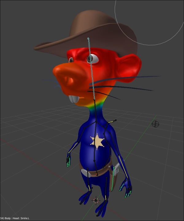
The weight paint of the Rat Cowboy (here the head influence is shown)
Weight Paint is a very useful technique, but sometimes it is not very accurate. It can be useful to assign weight precisely on some geometry components.
To do this, we must be in the Edit Mode and select the vertices to which we want to assign a weight. Then we can go in the Vertex Group menu (Properties | Data | Vertex Groups). There will be a Weight bar from which we must select the desired weight and click on Assign. If you don't have any group, you can click on the + icon.
Another nice feature is located in the Right Panel (N). There the Vertex Weight menu allows us to visualize the bones that influence the selected vertex and adjust the vertex directly. We will notice that the total weights assigned to a vertex group may exceed 1.000. In fact, Blender will add the total of influences and make an average.
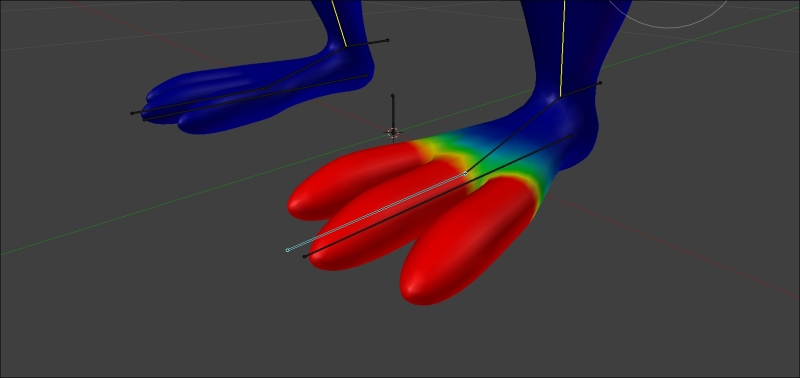
Correcting the weight paint of the toes.
If you have used the With Automatic Weight option, you should have a very few things to change. The arms, legs, and head deformations should be quite good.
However, the toes aren't working well because there isn't a bone for each toe. So we will fix this as follows:
- We will check the X-Mirror option, and we will select Toe bone.
- Now, we can paint with Add Brush to add some weight to the toes until we get a red color (100%).
- Then, we will need to remove the influence that the foot bone has on the toes. To do this, we will use the subtract brush. Now the foot shouldn't affect the toes.
Let's do the skinning of the belt. It is not a particularly easy element to skin because of its thickness and possible interpenetration with the body, but do not be discouraged. In this case, we will manually assign the weight to the vertices. This is shown in the following steps:
- We will start by selecting the belt, then select the Armature, and we will make them child and parent (Ctrl + P and select With Automatic Weight).
- In the Vertex Groups menu (Properties | Data | Vertex Groups), we will remove all the vertex groups except these: Hips, Thigh.L, and Thigh.R with the - button.
- First, we will assign a weight of 1.000 to the Hips vertex group, so the hips bone deforms all the belt.
- Then, we will select the vertices on the right half of the belt in the Edit Mode, and we will assign a weight of 0.2 to the Thigh.R group.
- We will do the same thing for the vertices on the left half of the belt but with Thigh.L.
- Then we will check the rotations of the Belt bone to verify some of the potential problems of transition. We will adjust the weight of a few vertices. The goal here is to create a gradient of weight at the center according to each thigh bone so that the thigh "attracts" some part of the belt in a smooth manner.

The weight of the left-hand side of the belt
The Weight Paint tools
If we select our mesh and observe the Data menu of the Properties panel, we can see Vertex Groups that matches the bones of the Armature. This menu, in Weight Paint mode, allows us to select and view the influence of each bone. The Weight Paint mode could be activated directly on the object. If the armature is in the Pose Mode, it is possible to select the bones by a RMB click as well while we are in the Weight Paint mode of the object.
In the Weight Paint mode, we can view the influence that each bone has on the geometry with a color play. Blue means a 0% influence, a greenish-blue color means 25%, green means 50%, yellow means 75%, orange means 85%, and red means 100%.
In order to modify the influence, we have several brushes that can be used exactly in the same manner as Texture Paint and Sculpt Mode in the left panel of the 3D viewport. These brushes allow us to paint bones influence directly on the mesh. In our case, we will use only three brushes. The brushes that will serve us for sure will be the Add, Subtract, and Blur brushes.
- The Add brush allows us to increase the weights
- The Subtract brush allows us to reduce the weights
- The Blur brush allows us to soften and mix the weights
The options of the brushes are exactly the same as with Texture Paint and Sculpt Mode. We can change the radius of the brush by pressing F and moving the mouse. Also, we can change the strength of the brush that will completely modify the impact of the brush. You can change the curve, too.
We can paint the weight in symmetry. To do this, the mesh must be perfectly symmetrical. We will check the X-Mirror option in the Option tab of Left Panel (T).
There are also a few useful options in the Weight Tools menu. For example, Mirror, to make a symmetric skinning and Invert, to invert the influence of our bones.
Note
For more information, you can have a look at the official Blender manual at this address: https://www.blender.org/manual/modeling/meshes/vertex_groups/weight_paint_tools.html.
The weight paint of the Rat Cowboy (here the head influence is shown)
Weight Paint is a very useful technique, but sometimes it is not very accurate. It can be useful to assign weight precisely on some geometry components.
To do this, we must be in the Edit Mode and select the vertices to which we want to assign a weight. Then we can go in the Vertex Group menu (Properties | Data | Vertex Groups). There will be a Weight bar from which we must select the desired weight and click on Assign. If you don't have any group, you can click on the + icon.
Another nice feature is located in the Right Panel (N). There the Vertex Weight menu allows us to visualize the bones that influence the selected vertex and adjust the vertex directly. We will notice that the total weights assigned to a vertex group may exceed 1.000. In fact, Blender will add the total of influences and make an average.
Correcting the weight paint of the toes.
If you have used the With Automatic Weight option, you should have a very few things to change. The arms, legs, and head deformations should be quite good.
However, the toes aren't working well because there isn't a bone for each toe. So we will fix this as follows:
- We will check the X-Mirror option, and we will select Toe bone.
- Now, we can paint with Add Brush to add some weight to the toes until we get a red color (100%).
- Then, we will need to remove the influence that the foot bone has on the toes. To do this, we will use the subtract brush. Now the foot shouldn't affect the toes.
Let's do the skinning of the belt. It is not a particularly easy element to skin because of its thickness and possible interpenetration with the body, but do not be discouraged. In this case, we will manually assign the weight to the vertices. This is shown in the following steps:
- We will start by selecting the belt, then select the Armature, and we will make them child and parent (Ctrl + P and select With Automatic Weight).
- In the Vertex Groups menu (Properties | Data | Vertex Groups), we will remove all the vertex groups except these: Hips, Thigh.L, and Thigh.R with the - button.
- First, we will assign a weight of 1.000 to the Hips vertex group, so the hips bone deforms all the belt.
- Then, we will select the vertices on the right half of the belt in the Edit Mode, and we will assign a weight of 0.2 to the Thigh.R group.
- We will do the same thing for the vertices on the left half of the belt but with Thigh.L.
- Then we will check the rotations of the Belt bone to verify some of the potential problems of transition. We will adjust the weight of a few vertices. The goal here is to create a gradient of weight at the center according to each thigh bone so that the thigh "attracts" some part of the belt in a smooth manner.
The weight of the left-hand side of the belt
Manually assigning weight to vertices
Weight Paint is a very useful technique, but sometimes it is not very accurate. It can be useful to assign weight precisely on some geometry components.
To do this, we must be in the Edit Mode and select the vertices to which we want to assign a weight. Then we can go in the Vertex Group menu (Properties | Data | Vertex Groups). There will be a Weight bar from which we must select the desired weight and click on Assign. If you don't have any group, you can click on the + icon.
Another nice feature is located in the Right Panel (N). There the Vertex Weight menu allows us to visualize the bones that influence the selected vertex and adjust the vertex directly. We will notice that the total weights assigned to a vertex group may exceed 1.000. In fact, Blender will add the total of influences and make an average.
Correcting the weight paint of the toes.
If you have used the With Automatic Weight option, you should have a very few things to change. The arms, legs, and head deformations should be quite good.
However, the toes aren't working well because there isn't a bone for each toe. So we will fix this as follows:
- We will check the X-Mirror option, and we will select Toe bone.
- Now, we can paint with Add Brush to add some weight to the toes until we get a red color (100%).
- Then, we will need to remove the influence that the foot bone has on the toes. To do this, we will use the subtract brush. Now the foot shouldn't affect the toes.
Let's do the skinning of the belt. It is not a particularly easy element to skin because of its thickness and possible interpenetration with the body, but do not be discouraged. In this case, we will manually assign the weight to the vertices. This is shown in the following steps:
- We will start by selecting the belt, then select the Armature, and we will make them child and parent (Ctrl + P and select With Automatic Weight).
- In the Vertex Groups menu (Properties | Data | Vertex Groups), we will remove all the vertex groups except these: Hips, Thigh.L, and Thigh.R with the - button.
- First, we will assign a weight of 1.000 to the Hips vertex group, so the hips bone deforms all the belt.
- Then, we will select the vertices on the right half of the belt in the Edit Mode, and we will assign a weight of 0.2 to the Thigh.R group.
- We will do the same thing for the vertices on the left half of the belt but with Thigh.L.
- Then we will check the rotations of the Belt bone to verify some of the potential problems of transition. We will adjust the weight of a few vertices. The goal here is to create a gradient of weight at the center according to each thigh bone so that the thigh "attracts" some part of the belt in a smooth manner.
The weight of the left-hand side of the belt
Correcting the foot deformation
If you have used the With Automatic Weight option, you should have a very few things to change. The arms, legs, and head deformations should be quite good.
However, the toes aren't working well because there isn't a bone for each toe. So we will fix this as follows:
- We will check the X-Mirror option, and we will select Toe bone.
- Now, we can paint with Add Brush to add some weight to the toes until we get a red color (100%).
- Then, we will need to remove the influence that the foot bone has on the toes. To do this, we will use the subtract brush. Now the foot shouldn't affect the toes.
Let's do the skinning of the belt. It is not a particularly easy element to skin because of its thickness and possible interpenetration with the body, but do not be discouraged. In this case, we will manually assign the weight to the vertices. This is shown in the following steps:
- We will start by selecting the belt, then select the Armature, and we will make them child and parent (Ctrl + P and select With Automatic Weight).
- In the Vertex Groups menu (Properties | Data | Vertex Groups), we will remove all the vertex groups except these: Hips, Thigh.L, and Thigh.R with the - button.
- First, we will assign a weight of 1.000 to the Hips vertex group, so the hips bone deforms all the belt.
- Then, we will select the vertices on the right half of the belt in the Edit Mode, and we will assign a weight of 0.2 to the Thigh.R group.
- We will do the same thing for the vertices on the left half of the belt but with Thigh.L.
- Then we will check the rotations of the Belt bone to verify some of the potential problems of transition. We will adjust the weight of a few vertices. The goal here is to create a gradient of weight at the center according to each thigh bone so that the thigh "attracts" some part of the belt in a smooth manner.
The weight of the left-hand side of the belt
Correcting the belt deformation
Let's do the skinning of the belt. It is not a particularly easy element to skin because of its thickness and possible interpenetration with the body, but do not be discouraged. In this case, we will manually assign the weight to the vertices. This is shown in the following steps:
- We will start by selecting the belt, then select the Armature, and we will make them child and parent (Ctrl + P and select With Automatic Weight).
- In the Vertex Groups menu (Properties | Data | Vertex Groups), we will remove all the vertex groups except these: Hips, Thigh.L, and Thigh.R with the - button.
- First, we will assign a weight of 1.000 to the Hips vertex group, so the hips bone deforms all the belt.
- Then, we will select the vertices on the right half of the belt in the Edit Mode, and we will assign a weight of 0.2 to the Thigh.R group.
- We will do the same thing for the vertices on the left half of the belt but with Thigh.L.
- Then we will check the rotations of the Belt bone to verify some of the potential problems of transition. We will adjust the weight of a few vertices. The goal here is to create a gradient of weight at the center according to each thigh bone so that the thigh "attracts" some part of the belt in a smooth manner.
The weight of the left-hand side of the belt
Now that our rigging is almost finished, we can opt for custom shapes. These are 3D objects that can replace the usual look of bones. The purpose is primarily aesthetic, but functional as well. We can make bone shapes that will go around the mesh and allow us to uncheck the X-ray option. Also, it will allow us to manipulate bones more easily.
We can hide the bones that do not require manipulation, such as the arms that are in fact only controlled by HandIK.L and HandIK.R.
To implement a custom shape, we must first to create a form, usually from a circle. We are going to make the custom shape of the Neck bone together and let you do the rest as this is very repetitive:
- We will add a circle (eight sides is enough) to the scene (press Shift + A and select Mesh | Circle).
- In the Edit Mode, we will select the opposite vertices on the Y axis, and we will connect them (J). This connection in the custom shape allows us to visualize the orientation of the bone better.
- We will rename this object as SHAPE_Circle_01.
- Now we will select the neck bone and SHAPE_Circle_01 in the Custom Shape option (Properties | Bone | Display | Custom Shape).
- There is often a problem with the axis of rotation and the scale. These must be adjusted in the Edit Mode. We can work on SHAPE_Circle_01 again in the Object Mode without modifying the custom shape applied to the neck bone.
- Once the custom shape is adjusted, we don't have to see the SHAPE_Circle_01 object, so we move it to another layer (M). We will choose the last layer to the right in our case. This layer is usually used as a garbage layer where we put unwanted objects.
We redo the same process for almost every controller bone. Some shapes are very often used, such as glasses for the eyes, but try to find custom shapes that fit your needs. They must be explicit and made of very few vertices.
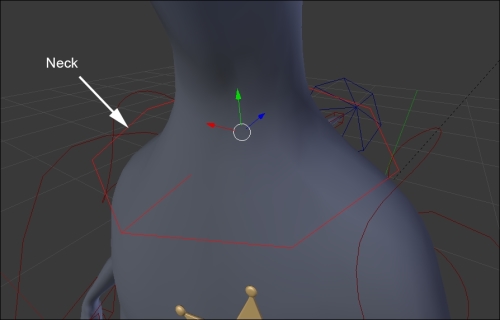
The custom shape of the neck bone
In the following sections, we are going to learn about shape keys and drivers. This will help us to create some very basic facial controls that we will use in the next chapter. Facial rigging is a long process, so we are not going to create a fully functioning facial rig here, but you will have all the tools needed to create your own if you want to.
A shape key is a method to store a change of geometry in a mesh. For instance, you can have a sphere object, add a shape key, move your vertices so that the sphere looks like a cube, and the shape key will store the changes for you. A shape key is controlled by a slider. The value of the slider corresponds to the distance each vertex has to move to get to the stored positions. As you can imagine, shape keys are very useful for facial rigging as they allow us to create different expressions and turn them on or off.
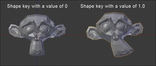
Example of a shape key with Suzanne
In this section, we will create five basic shape keys. They are eye blink left and right, smile left and right, and frown. This will be done as follows:
- First, we will need to select the object that will receive the shape keys. Then we will go to the Object Data tab of the Properties editor, and we will open the Shape Keys subpanel.
- When creating the shape keys, we always need to have a reference key that will store the default position of each vertex. To do this, we will click on the + button. It is called Basis by default.
- Now we can add a new shape key with the + icon and name it as EyeBlink.L. As you can see in the following, there is a value slider. At 0, the shape key is turned off, so change the value to 1.0 in order to view your changes in the Edit Mode.
- Now in the Edit Mode, we can change the left eye geometry to close the eye. You can use the Connected Proportional Editing tool (Alt + O) in order to smoothly move each eyelid to the center of the eye. Beware, you only want to move the eyelid's geometry, otherwise any other changes done will be part of the shape key.
- Next, we will mirror the shape key without tweaking our geometry on the right side again. We can do this because our mesh is perfectly symmetrical. We are going to create a new shape key based on the one that is currently active in the shape key stack. The value of EyeBlink.L is still at 1.0, so we can click on black arrow under the – icon and choose New Shape From Mix. Now, we have a new shape key with the same information as EyeBlink.L, but this not what we want. We will need to mirror this to the other side. To do this, we will again click on black arrow, and we will press Mirror Shape Key. We can also rename this as EyeBlink.R. Now if you change the value of EyeBlink.R, you can see that the right eye of the Rat Cowboy is closing perfectly. What a huge time-saver!
- The next two keys, Smile.L and Smile.R, are created using the same method. What you need to do is create a nice smile on one side and mirror it using New Shape From Mix and Mirror Shape Key.
- The last key to be created is a frown. To do this, we are just going to create a new key with the + icon and move the geometry between the eyebrows. There are tons of other things to know about shape keys, but for now this is all we are going to need.

Our facial shape keys
You might be thinking that animating directly shape key from the sliders is not very practical, and you are right! This is why we are going to use drivers. It is a method to indicate to an entity (object, bones, and so on) to control another value. In our case, we are going to tell Blender that the sliders of our shape keys are going to be controlled according to the transformations of the bones located on the face. This will give an impression that we are directly manipulating the head of our Rat Cowboy.
- The first thing to do is add three new bones to our Armature object in the Edit Mode. The first one will be located between the two eyebrows, and this will control the frown. The others are going to be near the mouth corner and will be symmetrical. They are called Frown, Smile.L, and Smile.R respectively. In order to control the eyes, we are going to use the bones we've used previously as targets.
- Now we will add a driver to the EyeBlink.L shape key by right-clicking on the value slider. Note that the value slider is now inaccessible, so it will be driven by another entity.

Adding a driver to a shape key
- Now split your view in a new editor of the Graph Editor type. Switch the mode from F-Curves to Drivers in the Graph Editor's header. As you can see, if you still have the rat mesh selected, you will have a new key on the left-hand side of Graph Editor. We can click on the white arrow on the left-hand side to unfold the group of keys, and we can select the EyeBlink.L one.
- Now we will open the right panel of Graph Editor (N), and under the Drivers subpanel, we can change the different settings. First, if you have an error, you can go to the user preferences under the File tab and check Auto Run Python Scripts. Drivers work with Python internally, so you must accept that it runs scripts. But don't be afraid, we are not going to code here!
- The first thing that we will change in our settings is the Ob/Bone field. We are going to choose the EyeTarget.L bone. So first choose the Armature object and then the bone. This will tell Blender that the target will be the bone that affects the driver.
- Now we are going to set Type to Y Scale and Space to Local. This means that, when we scale our target, the value of the variable called var in the upper field will take the value of Y Local scale of the bone.
- Now you need to imagine that the field called Expr is directly linked to the value slider of the shape key. You can even test this. If you enter
0, the eye will open, and if you enter1, the eye will close. So now what we can do is replace this field with the var variable that holds the value of the y local scale. You can now see that the Rat Cowboy's eye is closed. But if you scale it, it will open. We are close to the required result. - The last thing to do is change the expression so that it is open by default. We know that the Y local scale of our bone is 1 by default and that the "open state" of the eye corresponds to the 0 value of the shape key slider. So we can add the 1-var expression to the Expr field. If the Y local scale of the bone is 1, we will have 1-1 = 0 and the slider value will be 0, so the eye will be open. If the Y local scale of the bone is 0, we will have 1-0 = 1 and the slider value will be 1, so the eye will be closed. Done!
- We can replicate the same process with the other eye. In order to save time when creating the driver, you can simply right-click on the EyeBlink.L value slider, press Copy Driver, right-click on the EyeBlink.R, and choose Paste Driver. At this point, you just need to change which bone is controlling the key in the driver settings.
- For the smile driver, we will do a similar thing. But instead of feeding the variable with the Y local scale of the eye target bone, we are going to use the local Y location of the Smile.L bone. If you see a need to move the bone a lot in order to change the shape key, you can simply multiply var time a scalar in the Expr field. In our case, the expression will be var * 5.
- We can do the same thing for the other Smile.R bone and for the frown. The expression of Frown is -var * 10 in our case. As you can see, we have negated the var variable because we want to move the Frown bone down in order to control the shape key.
- As a bonus, we are going to lift the hat with the frown. To do this, we will copy our Frown driver to the X rotation of the hat object in the right pane of the 3D view (N). We will adjust the expression. In our case, the expression is simply -var.
- We will need to add a Limit Location constraint to the Frown bone as well. This will provide the animator with the ability to lift the hat high or low by locking the bone between a minimum and a maximum value on the Y axis in local space. To do this, we will change the settings of the constraint. We will check Minimum Y and set the value to -0.115, and then check Maximum Y and set its value to 0. Also, we can provide moves on the X and Z location by checking the other check boxes and setting their value to 0. Then we will need to select the Local Space.
- Now, we have minimum control over the Rat Cowboy's face in order to start animating our character. We advise you to go further yourself in order to gain experience with shape keys and drivers. For instance, you could add cheek puff or eyebrow shape keys.

The setup of the Frown driver in Graph Editor
What is a shape key?
A shape key is a method to store a change of geometry in a mesh. For instance, you can have a sphere object, add a shape key, move your vertices so that the sphere looks like a cube, and the shape key will store the changes for you. A shape key is controlled by a slider. The value of the slider corresponds to the distance each vertex has to move to get to the stored positions. As you can imagine, shape keys are very useful for facial rigging as they allow us to create different expressions and turn them on or off.
Example of a shape key with Suzanne
In this section, we will create five basic shape keys. They are eye blink left and right, smile left and right, and frown. This will be done as follows:
- First, we will need to select the object that will receive the shape keys. Then we will go to the Object Data tab of the Properties editor, and we will open the Shape Keys subpanel.
- When creating the shape keys, we always need to have a reference key that will store the default position of each vertex. To do this, we will click on the + button. It is called Basis by default.
- Now we can add a new shape key with the + icon and name it as EyeBlink.L. As you can see in the following, there is a value slider. At 0, the shape key is turned off, so change the value to 1.0 in order to view your changes in the Edit Mode.
- Now in the Edit Mode, we can change the left eye geometry to close the eye. You can use the Connected Proportional Editing tool (Alt + O) in order to smoothly move each eyelid to the center of the eye. Beware, you only want to move the eyelid's geometry, otherwise any other changes done will be part of the shape key.
- Next, we will mirror the shape key without tweaking our geometry on the right side again. We can do this because our mesh is perfectly symmetrical. We are going to create a new shape key based on the one that is currently active in the shape key stack. The value of EyeBlink.L is still at 1.0, so we can click on black arrow under the – icon and choose New Shape From Mix. Now, we have a new shape key with the same information as EyeBlink.L, but this not what we want. We will need to mirror this to the other side. To do this, we will again click on black arrow, and we will press Mirror Shape Key. We can also rename this as EyeBlink.R. Now if you change the value of EyeBlink.R, you can see that the right eye of the Rat Cowboy is closing perfectly. What a huge time-saver!
- The next two keys, Smile.L and Smile.R, are created using the same method. What you need to do is create a nice smile on one side and mirror it using New Shape From Mix and Mirror Shape Key.
- The last key to be created is a frown. To do this, we are just going to create a new key with the + icon and move the geometry between the eyebrows. There are tons of other things to know about shape keys, but for now this is all we are going to need.
Our facial shape keys
You might be thinking that animating directly shape key from the sliders is not very practical, and you are right! This is why we are going to use drivers. It is a method to indicate to an entity (object, bones, and so on) to control another value. In our case, we are going to tell Blender that the sliders of our shape keys are going to be controlled according to the transformations of the bones located on the face. This will give an impression that we are directly manipulating the head of our Rat Cowboy.
- The first thing to do is add three new bones to our Armature object in the Edit Mode. The first one will be located between the two eyebrows, and this will control the frown. The others are going to be near the mouth corner and will be symmetrical. They are called Frown, Smile.L, and Smile.R respectively. In order to control the eyes, we are going to use the bones we've used previously as targets.
- Now we will add a driver to the EyeBlink.L shape key by right-clicking on the value slider. Note that the value slider is now inaccessible, so it will be driven by another entity.
Adding a driver to a shape key
- Now split your view in a new editor of the Graph Editor type. Switch the mode from F-Curves to Drivers in the Graph Editor's header. As you can see, if you still have the rat mesh selected, you will have a new key on the left-hand side of Graph Editor. We can click on the white arrow on the left-hand side to unfold the group of keys, and we can select the EyeBlink.L one.
- Now we will open the right panel of Graph Editor (N), and under the Drivers subpanel, we can change the different settings. First, if you have an error, you can go to the user preferences under the File tab and check Auto Run Python Scripts. Drivers work with Python internally, so you must accept that it runs scripts. But don't be afraid, we are not going to code here!
- The first thing that we will change in our settings is the Ob/Bone field. We are going to choose the EyeTarget.L bone. So first choose the Armature object and then the bone. This will tell Blender that the target will be the bone that affects the driver.
- Now we are going to set Type to Y Scale and Space to Local. This means that, when we scale our target, the value of the variable called var in the upper field will take the value of Y Local scale of the bone.
- Now you need to imagine that the field called Expr is directly linked to the value slider of the shape key. You can even test this. If you enter
0, the eye will open, and if you enter1, the eye will close. So now what we can do is replace this field with the var variable that holds the value of the y local scale. You can now see that the Rat Cowboy's eye is closed. But if you scale it, it will open. We are close to the required result. - The last thing to do is change the expression so that it is open by default. We know that the Y local scale of our bone is 1 by default and that the "open state" of the eye corresponds to the 0 value of the shape key slider. So we can add the 1-var expression to the Expr field. If the Y local scale of the bone is 1, we will have 1-1 = 0 and the slider value will be 0, so the eye will be open. If the Y local scale of the bone is 0, we will have 1-0 = 1 and the slider value will be 1, so the eye will be closed. Done!
- We can replicate the same process with the other eye. In order to save time when creating the driver, you can simply right-click on the EyeBlink.L value slider, press Copy Driver, right-click on the EyeBlink.R, and choose Paste Driver. At this point, you just need to change which bone is controlling the key in the driver settings.
- For the smile driver, we will do a similar thing. But instead of feeding the variable with the Y local scale of the eye target bone, we are going to use the local Y location of the Smile.L bone. If you see a need to move the bone a lot in order to change the shape key, you can simply multiply var time a scalar in the Expr field. In our case, the expression will be var * 5.
- We can do the same thing for the other Smile.R bone and for the frown. The expression of Frown is -var * 10 in our case. As you can see, we have negated the var variable because we want to move the Frown bone down in order to control the shape key.
- As a bonus, we are going to lift the hat with the frown. To do this, we will copy our Frown driver to the X rotation of the hat object in the right pane of the 3D view (N). We will adjust the expression. In our case, the expression is simply -var.
- We will need to add a Limit Location constraint to the Frown bone as well. This will provide the animator with the ability to lift the hat high or low by locking the bone between a minimum and a maximum value on the Y axis in local space. To do this, we will change the settings of the constraint. We will check Minimum Y and set the value to -0.115, and then check Maximum Y and set its value to 0. Also, we can provide moves on the X and Z location by checking the other check boxes and setting their value to 0. Then we will need to select the Local Space.
- Now, we have minimum control over the Rat Cowboy's face in order to start animating our character. We advise you to go further yourself in order to gain experience with shape keys and drivers. For instance, you could add cheek puff or eyebrow shape keys.
The setup of the Frown driver in Graph Editor
Creating basic shapes
In this section, we will create five basic shape keys. They are eye blink left and right, smile left and right, and frown. This will be done as follows:
- First, we will need to select the object that will receive the shape keys. Then we will go to the Object Data tab of the Properties editor, and we will open the Shape Keys subpanel.
- When creating the shape keys, we always need to have a reference key that will store the default position of each vertex. To do this, we will click on the + button. It is called Basis by default.
- Now we can add a new shape key with the + icon and name it as EyeBlink.L. As you can see in the following, there is a value slider. At 0, the shape key is turned off, so change the value to 1.0 in order to view your changes in the Edit Mode.
- Now in the Edit Mode, we can change the left eye geometry to close the eye. You can use the Connected Proportional Editing tool (Alt + O) in order to smoothly move each eyelid to the center of the eye. Beware, you only want to move the eyelid's geometry, otherwise any other changes done will be part of the shape key.
- Next, we will mirror the shape key without tweaking our geometry on the right side again. We can do this because our mesh is perfectly symmetrical. We are going to create a new shape key based on the one that is currently active in the shape key stack. The value of EyeBlink.L is still at 1.0, so we can click on black arrow under the – icon and choose New Shape From Mix. Now, we have a new shape key with the same information as EyeBlink.L, but this not what we want. We will need to mirror this to the other side. To do this, we will again click on black arrow, and we will press Mirror Shape Key. We can also rename this as EyeBlink.R. Now if you change the value of EyeBlink.R, you can see that the right eye of the Rat Cowboy is closing perfectly. What a huge time-saver!
- The next two keys, Smile.L and Smile.R, are created using the same method. What you need to do is create a nice smile on one side and mirror it using New Shape From Mix and Mirror Shape Key.
- The last key to be created is a frown. To do this, we are just going to create a new key with the + icon and move the geometry between the eyebrows. There are tons of other things to know about shape keys, but for now this is all we are going to need.
Our facial shape keys
You might be thinking that animating directly shape key from the sliders is not very practical, and you are right! This is why we are going to use drivers. It is a method to indicate to an entity (object, bones, and so on) to control another value. In our case, we are going to tell Blender that the sliders of our shape keys are going to be controlled according to the transformations of the bones located on the face. This will give an impression that we are directly manipulating the head of our Rat Cowboy.
- The first thing to do is add three new bones to our Armature object in the Edit Mode. The first one will be located between the two eyebrows, and this will control the frown. The others are going to be near the mouth corner and will be symmetrical. They are called Frown, Smile.L, and Smile.R respectively. In order to control the eyes, we are going to use the bones we've used previously as targets.
- Now we will add a driver to the EyeBlink.L shape key by right-clicking on the value slider. Note that the value slider is now inaccessible, so it will be driven by another entity.
Adding a driver to a shape key
- Now split your view in a new editor of the Graph Editor type. Switch the mode from F-Curves to Drivers in the Graph Editor's header. As you can see, if you still have the rat mesh selected, you will have a new key on the left-hand side of Graph Editor. We can click on the white arrow on the left-hand side to unfold the group of keys, and we can select the EyeBlink.L one.
- Now we will open the right panel of Graph Editor (N), and under the Drivers subpanel, we can change the different settings. First, if you have an error, you can go to the user preferences under the File tab and check Auto Run Python Scripts. Drivers work with Python internally, so you must accept that it runs scripts. But don't be afraid, we are not going to code here!
- The first thing that we will change in our settings is the Ob/Bone field. We are going to choose the EyeTarget.L bone. So first choose the Armature object and then the bone. This will tell Blender that the target will be the bone that affects the driver.
- Now we are going to set Type to Y Scale and Space to Local. This means that, when we scale our target, the value of the variable called var in the upper field will take the value of Y Local scale of the bone.
- Now you need to imagine that the field called Expr is directly linked to the value slider of the shape key. You can even test this. If you enter
0, the eye will open, and if you enter1, the eye will close. So now what we can do is replace this field with the var variable that holds the value of the y local scale. You can now see that the Rat Cowboy's eye is closed. But if you scale it, it will open. We are close to the required result. - The last thing to do is change the expression so that it is open by default. We know that the Y local scale of our bone is 1 by default and that the "open state" of the eye corresponds to the 0 value of the shape key slider. So we can add the 1-var expression to the Expr field. If the Y local scale of the bone is 1, we will have 1-1 = 0 and the slider value will be 0, so the eye will be open. If the Y local scale of the bone is 0, we will have 1-0 = 1 and the slider value will be 1, so the eye will be closed. Done!
- We can replicate the same process with the other eye. In order to save time when creating the driver, you can simply right-click on the EyeBlink.L value slider, press Copy Driver, right-click on the EyeBlink.R, and choose Paste Driver. At this point, you just need to change which bone is controlling the key in the driver settings.
- For the smile driver, we will do a similar thing. But instead of feeding the variable with the Y local scale of the eye target bone, we are going to use the local Y location of the Smile.L bone. If you see a need to move the bone a lot in order to change the shape key, you can simply multiply var time a scalar in the Expr field. In our case, the expression will be var * 5.
- We can do the same thing for the other Smile.R bone and for the frown. The expression of Frown is -var * 10 in our case. As you can see, we have negated the var variable because we want to move the Frown bone down in order to control the shape key.
- As a bonus, we are going to lift the hat with the frown. To do this, we will copy our Frown driver to the X rotation of the hat object in the right pane of the 3D view (N). We will adjust the expression. In our case, the expression is simply -var.
- We will need to add a Limit Location constraint to the Frown bone as well. This will provide the animator with the ability to lift the hat high or low by locking the bone between a minimum and a maximum value on the Y axis in local space. To do this, we will change the settings of the constraint. We will check Minimum Y and set the value to -0.115, and then check Maximum Y and set its value to 0. Also, we can provide moves on the X and Z location by checking the other check boxes and setting their value to 0. Then we will need to select the Local Space.
- Now, we have minimum control over the Rat Cowboy's face in order to start animating our character. We advise you to go further yourself in order to gain experience with shape keys and drivers. For instance, you could add cheek puff or eyebrow shape keys.
The setup of the Frown driver in Graph Editor
Driving a shape key
You might be thinking that animating directly shape key from the sliders is not very practical, and you are right! This is why we are going to use drivers. It is a method to indicate to an entity (object, bones, and so on) to control another value. In our case, we are going to tell Blender that the sliders of our shape keys are going to be controlled according to the transformations of the bones located on the face. This will give an impression that we are directly manipulating the head of our Rat Cowboy.
- The first thing to do is add three new bones to our Armature object in the Edit Mode. The first one will be located between the two eyebrows, and this will control the frown. The others are going to be near the mouth corner and will be symmetrical. They are called Frown, Smile.L, and Smile.R respectively. In order to control the eyes, we are going to use the bones we've used previously as targets.
- Now we will add a driver to the EyeBlink.L shape key by right-clicking on the value slider. Note that the value slider is now inaccessible, so it will be driven by another entity.
Adding a driver to a shape key
- Now split your view in a new editor of the Graph Editor type. Switch the mode from F-Curves to Drivers in the Graph Editor's header. As you can see, if you still have the rat mesh selected, you will have a new key on the left-hand side of Graph Editor. We can click on the white arrow on the left-hand side to unfold the group of keys, and we can select the EyeBlink.L one.
- Now we will open the right panel of Graph Editor (N), and under the Drivers subpanel, we can change the different settings. First, if you have an error, you can go to the user preferences under the File tab and check Auto Run Python Scripts. Drivers work with Python internally, so you must accept that it runs scripts. But don't be afraid, we are not going to code here!
- The first thing that we will change in our settings is the Ob/Bone field. We are going to choose the EyeTarget.L bone. So first choose the Armature object and then the bone. This will tell Blender that the target will be the bone that affects the driver.
- Now we are going to set Type to Y Scale and Space to Local. This means that, when we scale our target, the value of the variable called var in the upper field will take the value of Y Local scale of the bone.
- Now you need to imagine that the field called Expr is directly linked to the value slider of the shape key. You can even test this. If you enter
0, the eye will open, and if you enter1, the eye will close. So now what we can do is replace this field with the var variable that holds the value of the y local scale. You can now see that the Rat Cowboy's eye is closed. But if you scale it, it will open. We are close to the required result. - The last thing to do is change the expression so that it is open by default. We know that the Y local scale of our bone is 1 by default and that the "open state" of the eye corresponds to the 0 value of the shape key slider. So we can add the 1-var expression to the Expr field. If the Y local scale of the bone is 1, we will have 1-1 = 0 and the slider value will be 0, so the eye will be open. If the Y local scale of the bone is 0, we will have 1-0 = 1 and the slider value will be 1, so the eye will be closed. Done!
- We can replicate the same process with the other eye. In order to save time when creating the driver, you can simply right-click on the EyeBlink.L value slider, press Copy Driver, right-click on the EyeBlink.R, and choose Paste Driver. At this point, you just need to change which bone is controlling the key in the driver settings.
- For the smile driver, we will do a similar thing. But instead of feeding the variable with the Y local scale of the eye target bone, we are going to use the local Y location of the Smile.L bone. If you see a need to move the bone a lot in order to change the shape key, you can simply multiply var time a scalar in the Expr field. In our case, the expression will be var * 5.
- We can do the same thing for the other Smile.R bone and for the frown. The expression of Frown is -var * 10 in our case. As you can see, we have negated the var variable because we want to move the Frown bone down in order to control the shape key.
- As a bonus, we are going to lift the hat with the frown. To do this, we will copy our Frown driver to the X rotation of the hat object in the right pane of the 3D view (N). We will adjust the expression. In our case, the expression is simply -var.
- We will need to add a Limit Location constraint to the Frown bone as well. This will provide the animator with the ability to lift the hat high or low by locking the bone between a minimum and a maximum value on the Y axis in local space. To do this, we will change the settings of the constraint. We will check Minimum Y and set the value to -0.115, and then check Maximum Y and set its value to 0. Also, we can provide moves on the X and Z location by checking the other check boxes and setting their value to 0. Then we will need to select the Local Space.
- Now, we have minimum control over the Rat Cowboy's face in order to start animating our character. We advise you to go further yourself in order to gain experience with shape keys and drivers. For instance, you could add cheek puff or eyebrow shape keys.
The setup of the Frown driver in Graph Editor
In this chapter, you've learned how to create a simple bipedal rig. All the knowledge that you've acquired could be used to push this further. For instance, you can add an FK/IK switch slider for the arms and the legs, add more facial controls, or create a more complex foot roll. If you want to see or use a more complex rig, you can check the rigify add-on (integrated in Blender by default). However, this rig will be quite interesting for animation. Talking about animation, let's start using our rig in the next chapter!