

Now that the drivers are set up, you can use the microUSB cable that came with the board to plug in the board to the USB port on your host machine, and the board will start booting up.
Note
Keep in mind that the USB 2.0 specification specifies a maximum current of 500 mA, which can be provided by a single port. This might not be enough if you connect many peripherals to the USB port using a USB hub. In those cases, you will need to use a 5-volt DC power supply to power the board.
On the board, there are five LEDs in total; they are all located on the side of the power and LAN connectors, as shown in this picture (many thanks to the BeagleBoard Foundation for allowing us to use this picture):
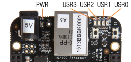
The default configuration for the user LEDs is:
USR0: This LED is a heartbeat LED; by default, it will keep flashing while the system is powered on
USR1: This LED blinks when the microSD card is being accessed
USR2: This LED will blink during the CPU activity
USR3: This LED will blink when eMMC memory is being accessed
When the system is starting up, it will not be accessible via USB before the USB drivers are initialized. To debug boot time issues, it is possible to see startup debug traces via a serial console connection on Header J1. This is an advanced topic that is described in Appendix, Security, Debugging, and I2C and SPI.
The boot process usually takes around 10 seconds, after which you will be able to connect to the board. There are several ways to connect to the target, and we will talk about two of those. If you are familiar with Linux, you probably already know how console logins work, but if you are not—no worries as we will cover some basics.