

The primary reason that Cinema 4D is so easy to learn and use is the interface. Once you learn some basic guidelines about navigating through the user interface, 3D tasks can be performed intuitively.
After touching on the basics of the interface, we'll go through the process of building an animated scene step-by-step.
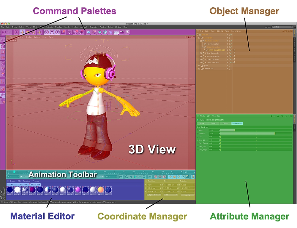
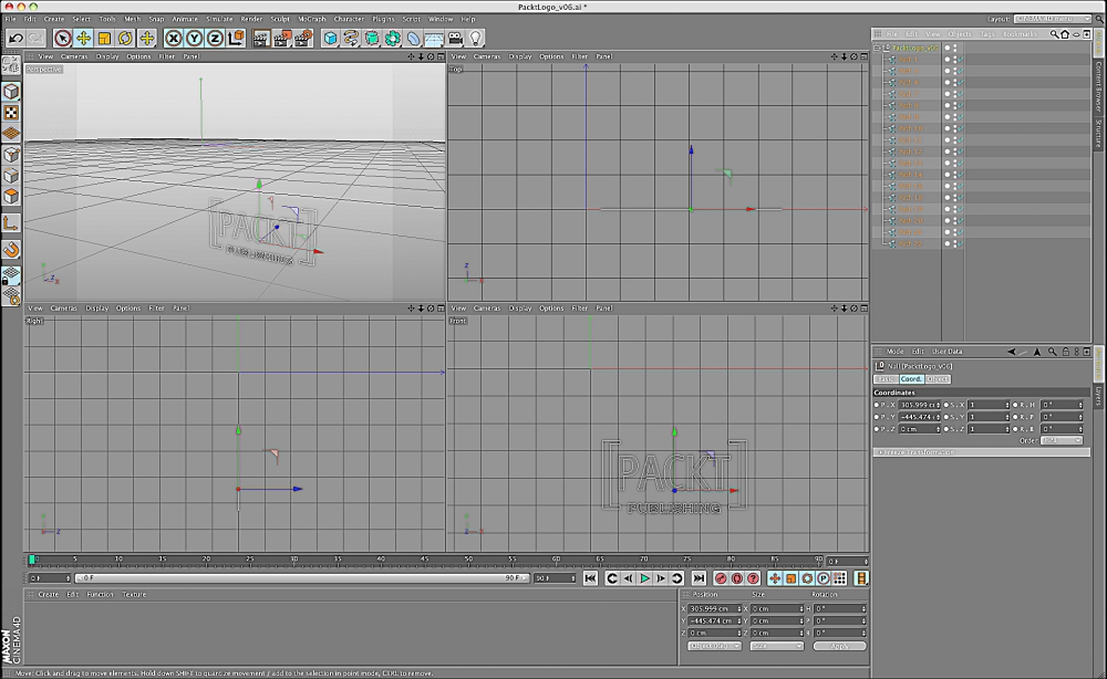
The following screenshot shows a breakdown of the default layouts in Cinema. The interface is completely customizable, and there are many other palettes that are not visible in the default startup layout. However, these palettes are the most important elements for getting started.
There are a few palettes being listed in the following list:
3D View: This is the 3D interface for your scene. Here you can navigate through your scene, build and modify 3D objects, and perform a host of other tasks intuitively in 3D space.
Object Manager: Here you can see a list of all of the objects in your scene, and edit the physical hierarchy of those objects. You can also rename objects here, and perform a variety of other important tasks through contextual menus.
Attribute Manager: Once objects are selected, this is where you edit all of the specific values and attributes for those objects. Here you can also add keyframes to attributes, link basic expressions, and add custom user attributes. Settings for many of the tools in Cinema 4D can also be configured here.
Command Palettes: An assortment of menus and buttons for creating new objects, transforming objects, and performing a variety of modeling tasks. As with the rest of the interface in Cinema 4D, Command palettes are completely customizable so you can add your own buttons and menus.
Coordinate Manager: This is an editor for making precise modeling adjustments. For example, you can use this palette to move an object to an exact position, and scale it to fit an exact bounding box.
Material Editor: This is where you create new materials and perform some basic material and texture related functions.
Animation Toolbar: A simplified overview of your scene's timeline. You can scrub through time and perform some primitive keyframe functions with this palette.
Besides the palettes we just came across, there are some other palettes as well, defined in the following list:
Timeline: This is where you edit keyframe animation. The timeline interface can switch between Key Mode, F-Curve Mode, and Motion System Mode. The timeline can be configured to filter animated channels in different ways. For example, you can show every animated channel in your scene, or link the timeline to your Object Manager palette so that only the animated channels of selected objects are visible.

A Timeline window, showing the same keyframe data in either Key Mode (top), or F-Curve Mode (bottom)
Picture Viewer: This palette is used for viewing rendered frames, or local renders in progress. You can browse through each frame that has been rendered since you opened Cinema 4D. The Picture Viewer window can show individual render passes, useful information regarding renders, and apply basic color filters in 32-bit floating point color.

Picture Viewer
XPresso Editor: XPresso is an incredibly powerful tool that allows users to create expressions to control and animate objects without writing a single line of code. Object attributes can be linked to XPresso nodes and other attributes at will through a graphic user interface.
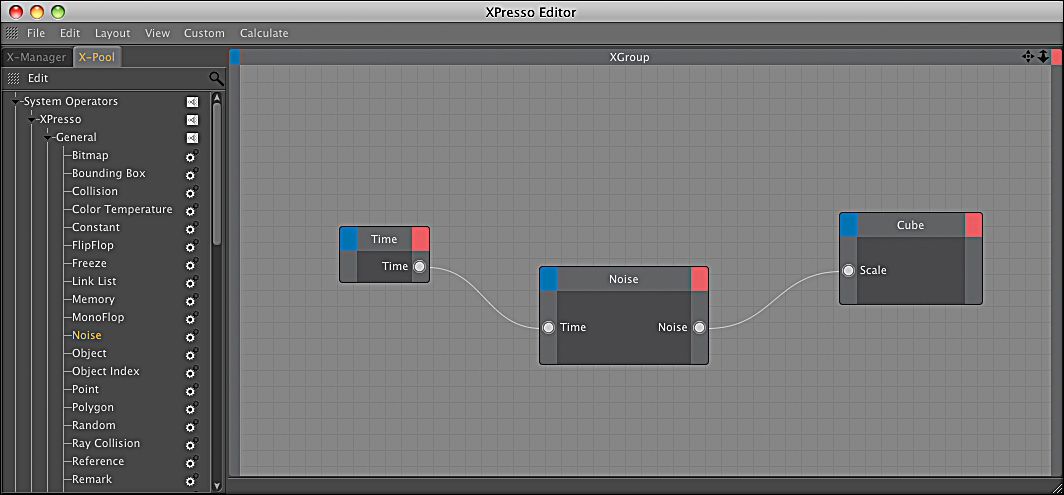
XPresso Editor
Script Manager, Script Log, and Console: For power users who want to write scripts to alter or control their scenes, the Script Manager palette provides an interface to do so within Cinema 4D. Scripts can be written with either Python or C.O.F.F.E.E. (a proprietary language similar to C++, Java, or PERL). The Script Log displays commands from Cinema 4D's runtime. The Console is used for debugging and entering a single line of code.

Script Manager palette, Script Log, and Console
Content Browser: Cinema 4D comes with a library of presets and resources for building scenes. Depending on your license of Cinema 4D (Prime, Broadcast, Visualize, or Studio) you will have access to different libraries. Example scenes can be invaluable when you're trying to figure out how a feature is used in a scene.
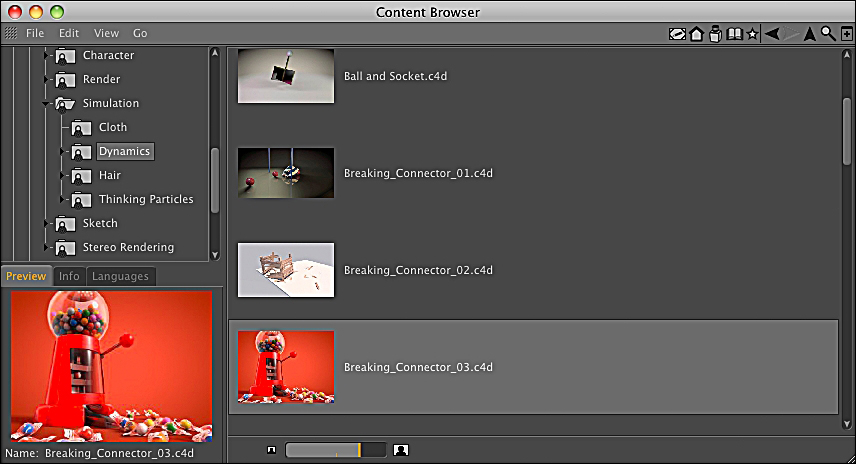
Content Browser
Help: While working with Cinema 4D, the user guide is always at your fingertips. Not only are features of the program well documented, but an interactive help feature lets you jump to any topic directly from the user interface.
As with every 3D program, there are hotkeys for orbiting, dollying, and tracking in the 3D windows. For most users experienced with another package you'll feel at home using the Alt key and a 3-button mouse. By default, you can also use keys 1, 2, and 3 if you only have a 1-button mouse. The following list depicts the default hotkey functions:
|
Single-button mouse |
3-button mouse | |
|---|---|---|
|
Orbit camera |
3 + click and drag |
Alt + left mouse button |
|
Track camera |
1 + click and drag |
Alt + middle mouse button |
|
Dolly camera (Z-axis move) |
2 + click and drag |
Alt + right mouse button |
By default, a new Cinema 4D scene will display the main perspective view. To switch to 4-view mode, you can click on the window icon on the upper-right of the view, click on the middle mouse button in the perspective view, or use options in the Panel view menu to configure views.
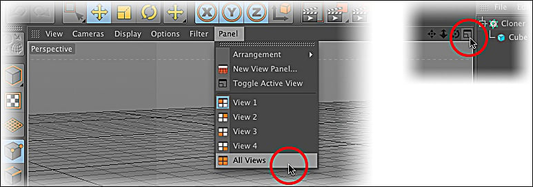
A couple different ways to get to a split-view
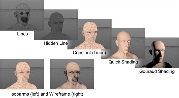
In each of the 3D views you can set a display mode and a level of detail. The different display modes are as follows:
Gouraud: Use this mode to preview a rough approximation of lighting and textures in OpenGL. This is the slowest display mode.
Quick: This mode is similar to Gouraud mode, but refreshes faster because lighting is not displayed. A default light is used to preview the shape of objects.
Constant: This mode displays objects evenly without a default light. However, textures are still displayed by default. It is faster than the Quick Shading mode.
Hidden Line: In this mode textures and material colors are ignored, and every object is displayed using a default gray color with polygonal edges visible. This is the fastest display method wherein polygonal faces are still visible.
Lines: This is the fastest and roughest display mode. This is useful for either speed or for performing very specific modeling tasks.
In all display modes, you have the option of displaying lines or polygonal edges. For full detail, use the Wireframe mode. For parametric detail, use the Isoparms mode. The following figure shows examples of some display modes:
One important thing to note about the viewer is that you can preview renders directly inside a 3D view. To preview renders inside a view, use the hotkey Ctrl + R. To toggle an interactive render region, use the hotkey Alt + R. You can also use the Render menu or the rendering portion of the top Command palette.
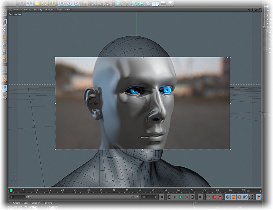
An interactive render region
Within a 3D view, many objects can be edited via interactive manipulation handles. For example, directly inside the 3D view, you can control a spot light's cone and falloff distance.
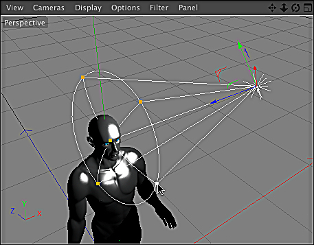
Adjusting a spot light's cone in a 3D view
Here are some simple rules that are applicable throughout the interface, and will save you a lot of time.
This trick lets you create a copy of an object, tag, material, keyframe, or pretty much anything else. Whether in the Object Manager palette, Material Manager palette, 3D View palette, or XPresso Editor palette, drag an item as if you are moving it, then hold down the control/Ctrl key (for Mac/Windows users respectively) to create a clone in the new position once the mouse is released.
To create a keyframe on any attribute, control/Ctrl + click (hold down the control key on your keyboard and click on the mouse) on the little circle next to that attribute. Alternately, to add a keyframe to multiple attributes, highlight the first attribute, control/Ctrl + click to highlight additional attributes, then control/Ctrl + click the little circle next to any of the highlighted attributes to add a keyframe to all of them.
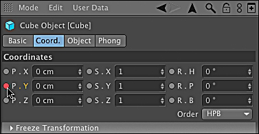
control/Ctrl + click adds a keyframe
You can access time-saving contextual menus by right-clicking on an object in a variety of different palettes. If you need help on a specific object or attribute, right-click on that object or attribute and click on the Show Help... command. The Help window will be launched and you will be taken straight to the relevant page.
Now that we've taken a cursory look at the Cinema 4D interface, let's build our first 3D scene!
For this tutorial, we'll be using a free third-party plugin named Thrausi to shatter a 3D logo. Thrausi 1.22 is provided free of charge by Nitro4D, and Thrausi 1.36 is available for download for a small donation. Nitro4D also makes a more powerful commercial object-shattering plugin called NitroBlast.
Before we begin, we'll need to download Thrausi from Nitro4D's website and install it. The website address is http://nitro4d.com/blog/freebie/thrausi/.
If you would like to purchase NitroBlast instead, you can find that plugin at http://nitro4d.com/blog/donationware/nitroblast/.
We downloaded Thrausi 1.22, which comes in the form of a ZIP archive (Thrausi-1.22-R12.zip).
Extract the ZIP archive in the default fashion, creating a directory called Thrausi 1.22 R12. Move that entire directory into the Plugins folder of your Cinema 4D installation. The Plugins folder can be found in the following location:
MAC OS X users follow the path
/Applications/MAXON/CINEMA 4D R14/pluginsWINDOWS users follow the path:
C:\Program Files\MAXON\CINEMA 4D R14\plugins
The next time you launch Cinema 4D, you should have a working installation of the Thrausi plugin!
To import a logo from Adobe Illustrator (AI), make sure that the vector logo file is saved in Adobe Illustrator 8.0 or an earlier format.
To open the vector artwork in a fresh scene, you can use the main menu (File
|
Open...). To import the artwork into a scene that is already open, use the Merge... option instead of the Open... option (File
|
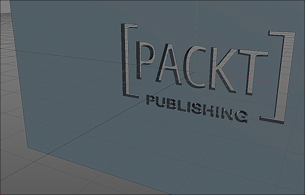
Merge...). Either way, browse to the AI file for your logo. When the logo first comes in, it will likely be off-center and the paths need to be organized before we proceed with modeling.
The logo imported into C4D, before doing any cleanup
First, let's center the pivot of the logo. Select the top group of the imported logo in the Object Manager palette. Launch the Axis Center dialog (Mesh | Axis Center | Axis Center). In the Axis Center dialog, turn on the options for Include Children and Use All Objects.
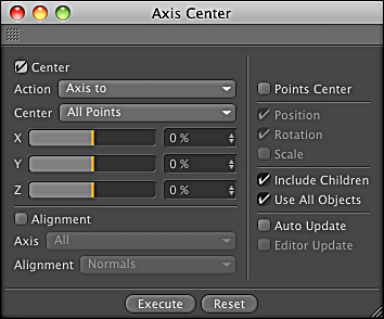
The Axis Center window, with options set
Click on the Execute button. The pivot of the main logo group will be moved to the center of the logo.
With the main group still selected, set the P.X, P.Y, and P.Z values in the Attribute Manager to 0. The logo now sits at the center of the scene.
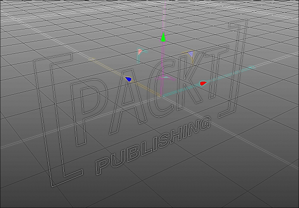
The logo, with its pivot centered and placed at the center of the word
Next, we'll want to organize all of the paths that came in to prepare them for modeling. This involves the following three concepts:
Connecting splines
Exploding segments from splines
Renaming splines
We'd like to simplify our scene by combining splines that don't need to be separate objects. This will make everything simpler later on.
Select multiple splines that you'd like to combine.
Right-click on the Object Manager palette to bring up a contextual menu, then select the Connect Objects + Delete command. This will combine the paths into one object and delete the originals.
Using the Connect Objects + Delete command to connect paths
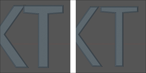
It should be noted that combining paths will create a compound path, potentially creating holes if used for a NURBS generator, such as an Extrude, as shown in the following screenshots:

To the left, separate paths. To the right, one compound path created via Connect Objects + Delete
Now we'll create a background for the logo to rest on. However, instead of creating a simple flat background, we'll create one that the logo fits into like a puzzle piece. This will give us much more depth once the logo is shattered, and will serve as a background for the logo to read against. To create a background, follow the subsequent steps:
Create a Rectangle generator, either through the top Command palette or through the main menu (Create | Spline | Rectangle).
Edit the Width and Height properties of the rectangle in the Attribute Manager palette, so that it's large enough to fill the screen in the final animation.
The Connect Object + Delete command won't work with procedural generators, so we'll need to commit the Rectangle Generator to a non-procedural spline first. Right-click on the rectangle and use the Make Editable command. The rectangle's icon will change in the Object Manager palette from a rectangle to a common spline (the default hotkey for this operation is the C key).
Duplicate the splines of the logo. A fast way to do this is to select all the splines in the Object Manager palette and control/Ctrl + drag them to a different spot in the hierarchy. This will create clones of the splines.
Combine the duplicated logo splines with the committed rectangle. Select the duplicated splines and the rectangle. Right-click on one of the selected splines in the Object Manager palette and use the Connect + Delete command to combine all of these splines into one compound path.
A background created using a compound path within which the logo actually fits into
In some cases, you'll want to separate a compound path into multiple paths. To do so, select the compound path and use the Explode Segments command (Mesh | Spline | Explode Segments).
Once we are happy with the logo's splines, it's a good idea to rename them. To do so, select a spline in the Object Manager palette and hit the Enter key. You can use the up and down arrows to quickly move through and rename all of your paths. Once you are done renaming, hit the Enter key again or change your selection to finish renaming.
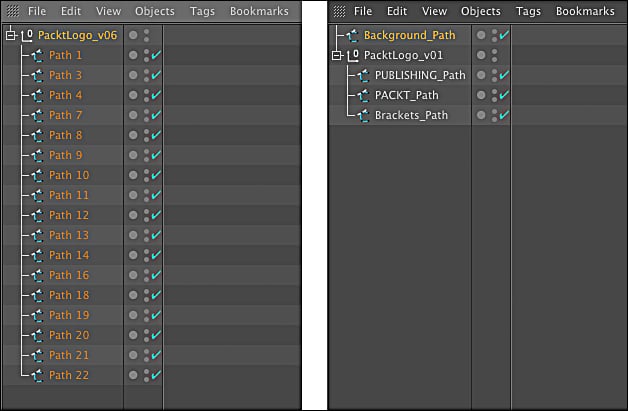
The Object Manager palette, before and after organizing our paths
Now it's finally time to start modeling.
Ordinarily, we would create an Extrude generator, place it in the hierarchy, and parent the spline to it. Here, we'll use a special trick to extrude each spline in half the time it would normally take.
With a path selected, hold the Alt/Option key when you create the Extrude object. This works whether you create the Extrude generator through the menu or through the top Command palette. You'll notice that the path is automatically parented to the Extrude generator, and that the Extrude generator's pivot is set up properly.
For your logo, set up all of the extrusions that you'll need. In our case, we set up one extrude for the PACKT text, one for the PUBLISHING text, and one for the box brackets.
Edit the properties of the different extrusions until you are happy with them. To add bevels to your extrusions, navigate to the Caps tab in the Attribute Editor and change the Start and End properties to Fillet Cap. You can then edit additional properties to get the type of bevels that you'd like.
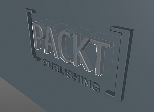
There is one very important thing to note about bevels. By default, bevels grow outward from your original path. In many cases this can have an undesired effect since the overall thickness of your logo will increase and it will look different from the original vector art. To fix this, turn on the Constrain option in the Caps section of the extrude generator's attributes.
On the left, constrain left off. On the right, constrain turned on and the logo is preserved
We now have our shapes the way we like them. The logo is extruded and our bevels are set up nicely. Also, most of the extrusion slides into a compound shape that fills our background.
Now let's create and assign materials to different parts of the logo.
Create a material in the Material Editor window, either by double-clicking on the empty space or through the Material Editor window's menu (Create | New Material).
Assign the material to an object by dragging the material from the Material Editor onto the Extrude generator. Notice that the Extrude generator now has a Texture tag assigned to it.
Edit the material as you want. You can select the material in the Material Editor, or double-click the Texture tag in the Object Manager palette. In the Basic tab of the material, you can turn different surface properties on or off, such as Specular, Reflection, and so on. Once a surface property is enabled, a tab appears for that property for further editing.
Our logo with materials assigned
Now it's time to shatter the logo using Nitro4Ds Thrausi plugin. Follow these steps to shatter the logo:
Select the object you wish to shatter.
Launch the Thrausi interface, through the main menu (Plugins
|Thrausi 1.22 R12|Thrausi). If you have the NitroBlast plugin, you can use that plugin instead.Set the value in the Pieces field to the number of actual pieces you'd like to generate.
Select the type of shatter you'd like to perform. Here, we chose Voronoi.
Click the Break Now button at the bottom of the Thrausi interface. It may take a few minutes to calculate the shatter.
For the sake of this tutorial, delete the Rigid Body simulation tags on the resulting Fracture groups.

The logo, now fractured
Each letter has been shattered and put into a MoGraph Fracture group. This is a special group that will allow us to assign MoGraph effectors to the shards. If you'd like to regroup the shards into different Fracture objects to better organize your scene, it's perfectly safe to do so.
Since we're not using dynamics for this tutorial, we deleted the Rigid Body tags from the Fracture groups. If you wanted to use dynamics to animate the shards, you could leave these tags for a start.
One thing you may notice is that the bevels of the logo no longer have sharp edges. That's because the phong shading angle is too high. If the phong angle is 80 degrees, then any polygonal edge with 80 degrees or less between adjacent face normal will appear smoothed. These properties are controlled by the Phong tag.
Now let's edit the phong tags on the shards:
Select all of the Phong tags of the shards. You can do so by dragging a selection marquee in the Object Manager palette. You can also select the Phong tag of the first object in the list, then press the Shift key as you select the Phong tag of the last object. All of the Phong tags will be selected.
Set the value of the Phong Angle field to something less than 45 degrees, such as 30.

Before and after fixing the Phong tags
For the purposes of this tutorial, we'll be using MoGraph effectors to move the shards instead of dynamics.
Now we'll create a Plain effector to spread out the shards. Just follow the subsequent steps to create a Plain effector:
Select all of the MoGraph Fracture groups.
Create a Plain effector through the main menu (MoGraph
|Effectors|Plain). Since the Fracture groups are selected, the Plain effector is automatically assigned to them.In the Parameter tab of the Plain effector attributes, set the P.X, P.Y, and P.Z attributes to 0, 0, and -500 respectively.
Also in the Parameter tab, set the Weight Transform attribute to 100%. This adds an invisible weight value per shard that can be inherited by other effectors later on.
In the Falloff tab, set the Falloff property to Linear. Note that the falloff property's orientation is set to Z, and that falloff controls are now visible in the 3D view.
Set the Falloff attribute to 100%.
Move the Plain effector on the z axis, and adjust the falloff's Size Z until the Plain effector's falloff barely encompasses the logo.

Adjusting the Plain effector's Z position and falloff
Turn on the Fracture groups. You can click on the little red cross next to the Fracture groups in the Object Manager palette, or turn on the Enabled checkbox in the Basic tab of the Fracture group's attributes.
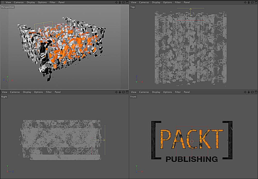
If everything is done correctly, you should see all your pieces floating forward. The Plain effector's linear falloff ensures that pieces closer to the front of the logo come out further as shown in the following screenshot:
Right now the pieces are only moving on the z axis. We'll need to scatter them slightly on the x and y axes, as well as give them some rotation.
Luckily, we set up the Plain effector so that the weight falloff gets recorded on the individual pieces, this value supports controlling other movement, rotation, and scale of the shards with additional effectors.
Let's create a Random effector that will inherit weight from the Plain effector. To create a Random effector follow the subsequent steps:
Select all of the MoGraph Fracture objects again.
Create a Random effector (MoGraph
|Effectors|Random).In the Falloff tab of the Random effector's Attributes tab, set the Weight property to 0%. This ensures that Random Effector uses the weight created by the Plain Effector object, and does not create a weight of its own.
In the Parameters tab of the Random effector's attributes, turn on the Rotation option, and enter some values for R.H, R.P, and R.B. We used the value 90 for each field.
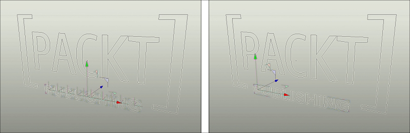
Also in the Parameters tab, set the P.X and P.Y fields to a value that breaks up the position of the shards, without forcing them to intersect with each other too obviously.

Before and after adding a Random Effector (from the Front view)
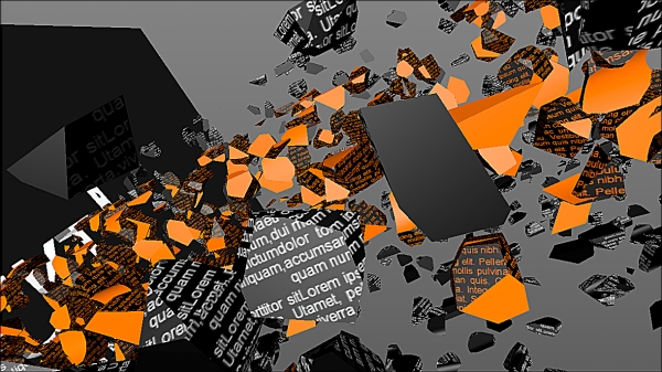
One cool thing about Thrausi and Nitroblast is that they create and assign a new material to the inner surfaces of the shards.
We're going to add a file texture to the color channel of that material by following these steps:
Select the material that is assigned to the inner surfaces. You can find it quickly by looking through the tags on an individual shard, and double-clicking the proper Texture tag.
In the Color tab of that material, click the little browse icon (which looks like …) next to the Texture label, and browse to the texture file you'd like to use.
To change tiling or texture placement, you'll need to do so on the shards' tags. Since there are too many shards to do this manually, we'll use a contextual menu in the Material Editor window to select all of the tags associated with that material. Therefore, to change the tiling or texture placement, follow these steps:
Right-click on the material in the Material Editor window and navigate to Select Texture Tags/Objects. All of the Texture tags that use that material are now selected.
In the Attribute Manager palette, you can edit all of the selected tags at once. Change the number of tiles and any other aspects of the texture projection that you'd like to edit.

A material assigned to the inner surfaces of the shattered logo
The time has come to add animation to our scene. Before we add any keyframes, we'll set the frame rate and frame duration of the animation by following these steps:
Open the Project Settings window. You can do so through the main menu (Edit
|Project Settings) or you can use the default hotkey, Ctrl + D.In the Attribute Manager palette window, set the FPS attribute value, and other time properties as you need to. We set the FPS attribute value to 24, Minimum Time and Preview Min Time attribute values to 1, Maximum Time and Preview Max Time attribute values to 240. This will make our animation exactly 10 seconds long.

The Project Settings window with FPS and frame range set
Let's also set the final output resolution before we begin, so we'll see the proper aspect ratio represented while looking through and animating our camera. To set the final output resolution follow these steps:
Launch the Render Settings window, either through the top Command palette or through the main menu (Render
|Edit Render Settings…).Select the Output tab from the list on the left.
Set the Width and Height attributes to what you require for final output resolution. We're using the values 1,920 and 1,080 for width and height.
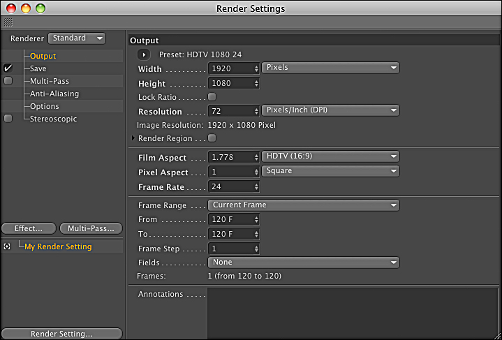
The Render Settings window with the output resolution set
The plan for our animation is to have the logo form over the course of a single shot. In the beginning, the camera will be off to the side and all of the shards of the logo will be floating out in space. As the camera orbits to the front, the shards will settle into place, revealing the logo at the end.
The logo needs to be fully built halfway through the animation. This will ensure that we can have a little camera drift at the end, and plenty of time to read the logo after it's formed. Let's set some keyframes on the Plain effector to block this out. Since the Random effector inherits the weight of the Plain effector, we won't need to set any keyframes on the Random effector at all.
Let's animate the Plain effector object. The Random effector will be animated indirectly as a result, because of the weight inheritance we set up previously. To animate the Plain effector, perform the following steps:
Go to Frame 1. You can click in the timeline to jump to anywhere within the preview time range, or type
1into the current frame field just to the right of the timeline.Select the Plain effector.
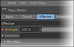
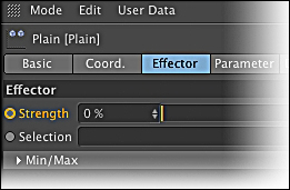
In the Attribute Manager palette, navigate to the Effector tab and locate the Strength property.
Control-click the little gray circle to the left of the Strength property. The circle should become red, showing that this value is keyed in this frame as shown in the following screenshot:
Go to the frame in the middle of your animation. For us, this is frame 120. Note that the little circle next to the Strength property is now hollow with a red stroke, as seen in the following screenshot. This means that the property is controlled by keyframe data, but there is no keyframe on the current frame.

Change the Strength property of the Plain effector to 0%. Note that the little circle next to the Strength property is now empty but has a yellow stroke, shown in the following screenshot. This means that the property is animated and changed, but you'll need to set a keyframe if you want to preserve the change.
Set another keyframe on the Strength property for this frame.
Let's build a camera rig which will allow us to get a nice orbiting camera move. We could simply keyframe a camera at the start position and the end position, but that would give us a linear move. Instead, we'll parent a camera to a null that will rotate to create an orbiting move.
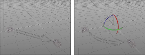
The difference between simply setting keyframes on a camera's position (left) and parenting the camera to a Null object that is rotating (right)
Now follow these steps to parent a camera to a null that will rotate to create an orbiting move:
Create a Camera object. You can do so either through the top Command palette or through the main menu (Create
|Camera|Camera).Set position of the Camera object. In the Coord. tab of the Attribute Manager palette, set the attribute values for P.X and P.Y to 0cm. Set the P.Z attribute position to a negative value, such as -500cm.
Reset the rotation of the Camera object. In the Coord. tab of the Attribute Manager palette, set the R.H, R.P and R.B attribute values to 0.
Create a Null object to parent the Camera object to, either through the top Command palette or through the main menu (Create
|Object|Null).Parent the Camera object to the Null value. In the Object Manager palette, drag the Camera object onto the Null value.
Make your new Camera object active. You can do this through the 3D view menu (Cameras | Use Camera | Camera), or by clicking the little target icon to the right of the Camera object in the Object Manager palette window.

Making this camera object the active camera for animation and rendering
We've blocked out the animation of the shards. Now we'll animate our new camera rig. Remember, the only position we'll control on the Camera object itself is P.Z. We'll leave the P.X and P.Y attributes of the Camera object at 0 for the entire animation.
Now let's animate the Camera object. We'll work backwards from the frame when the shards land in their final position.
Go to the frame when the shards settle. For us that's frame 120.
Move the Camera object's parent Null object to the center of the logo.
Set the Focal Length and P.Z properties of the camera to create your final frame. We wanted a wide-angle lens, so we set the Focal Length attribute to 18mm.
Set a keyframe on the Camera object's P.Z property.
Set a keyframe on the Camera object's R.B property (here, B stands for Bank).
Select the camera's parent Null object.
Set a keyframe on the Null object's P.Z property.
Set a keyframe on the Null object's R.H and R.P properties (here, H and P stand for Heading and Pitch, respectively).

Our animation at frame 120
Now we'll set keyframes for the camera at the beginning of our animation by performing the following steps:
Go to the first frame of your scene.
Rotate the Null object using the H and P properties, so that the camera is orbited around to a side angle.
Move the Null object on the z axis to the center of the shards.
Move the Camera object on the z axis to find a first frame that you're happy with.
Rotate the camera's Bank object if you'd like to give your first frame a dutch tilt.
Set keyframes on all of the properties that we've altered to create our first frame. This includes the Camera object's P.Z and R.B properties, and the Null object's R.H, R.P, and P.Z properties.
Our animation at frame 1
Finally, we'll add a little drift to the Camera object after the shards have landed, so there's still some slight movement while the audience reads the logo. Let's add a little drift:
Go to the last frame of your animation. For us that's frame 240.
Move the Camera object slightly further back on the z axis. This will create a slow drift after the logo settles.
Keyframe the Camera object's P.Z property.
To preview your animation, use the Make Preview... command, either through the top Command palette or through the main menu (Render | Make Preview…).

Here are some frames from our animation preview
The next step after achieving an animation that we're content with is to add light to our scene. We'll use a combination of a spotlight and global illumination. The spotlight will give us a nice key light, and the global illumination will fill in the ambient light in a realistic fashion. We'll use a target light rig to set up our key light. To light a scene follow these following step:
Create a Target Light object. You can do this either through the top Command palette or through the main menu (Create
|Light|Target Light).In the Details tab of the Light object's attributes, change the Falloff property to Inverse Square (physically accurate). This will set up a realistic falloff on the light, so that it behaves like light in the real world.

To the left, a normal light. To the right, a light using inverse square (physically accurate) falloff
In the Shadow tab of the Light object's attributes, change the shadow type from None to Area. This will create soft and realistic shadows.
Go to a frame in your scene when the logo is fully formed.
Create an Interactive Render Region in your camera's 3D view. You can do this either through the top Command palette or through the main menu (Render | Interactive Render Region). This will allow you to preview the lighting as you set it up.
Looking through the light in a 3D view makes it easy to adjust your light. Let's set that up and fine tune our Light object.
Select the Light object.
Set up one of your 3D views to look through the Light object. To do so, use the menu in the 3D view (Cameras
|Set Active Object as Camera).You can orbit, track, and dolly in the 3D view to establish where the Light object's source is.
Move the target to the position where you want the light to be aimed.
Adjust the outer angle of the light's cone, the light's falloff distance, and the properties of the area shadows in the Details tab of the Light object's attributes. You can also edit some of these properties in the 3D view by dragging manipulation handles.
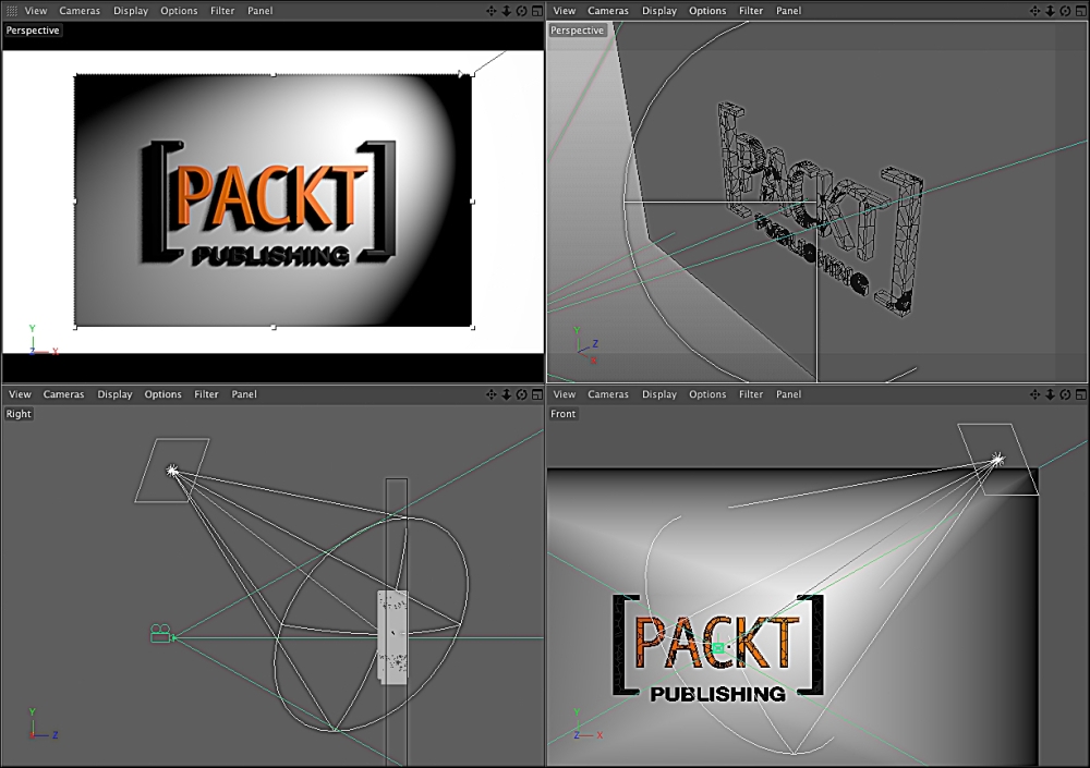
Using an interactive render region in the upper-left view, while in the upper-right view we're looking through the spotlight. The lower-left and lower-right views shown here are simply orthographic Right and Front views in our four-view layout.
Now, let's set up the Global Illumination (GI) object:
Launch the Render Settings window, either through the top Command palette or through the main menu (Render
|Edit Render Settings…).To add the GI, click on the button labeled Effect to the left of the Render Settings window, and select the Global Illumination option from the list of effects.
Create a Sky object, either through the top Command palette or through the main menu (Create
|Environment|Sky).Create a new material.
Assign the new material to the Sky object.
Edit the properties of the Sky object's material. This will be used for the GI, and also for the background and reflections in any materials that have the Reflection option turned on. You can apply an HDRI image material to the sky, but we just gave it a bright gray color.
You will likely find that you want to tweak lights and materials to get the look you want. We turned the Light object's intensity down and tweaked its position once the GI was added to the scene. We also added a very slight reflection to the outer surfaces of the logo.
In production, you often need to render as quickly as possible. Some of the effects we'll use, such as 3D depth-of-field, could be closely simulated in compositing, thus saving a lot of time in the end. However, it's still a good idea to see how such effects can be achieved with the highest quality by applying them during your actual 3D render.
Let's set up some photographic effects on the camera. First, we'll need to switch the primary renderer to Physical. The Physical renderer option needs to be turned on to take advantage of certain effects. This option can be enabled through the Render Settings window by performing the following steps:
Launch the Render Settings window.
In the upper-left of the Render Settings interface use the drop-down menu labeled Renderer to change the primary renderer from Standard to Physical.
Once the renderer is changed, a new option labeled Physical appears in the list to the left column of the Render Settings. Click on that new option to edit the Physical Renderer settings.
Turn on the Depth of Field option.
Change the Sampling Quality option to Medium.
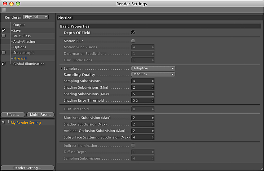
Using the Physical Renderer in the Render Settings
Now let's set up some effects on the camera. We'll add a focus pull with a shallow depth-of-field and slight chromatic aberration:
Select your render camera object.
In the Physical tab of the Camera object's attributes, enter a very low F-Stop option. The right value will depend on your taste, how wide your lens is, and the physical scale of your scene. Because we want an extreme effect, and because we're using a wide angle lens, we'll need to use a very low value for F-Stop option, such as
1.If you want to introduce some small imperfections to your lens, you can turn up the values for Chromatic Aberration and Vignetting Intensity option. Remember though that vignetting can alternatively be achieved very easily in a compositing application later on.
Create a Null object to use as a target for the focus pull.
Give your Null object a clever name, such as
Focus Null.Select a Camera object.
Navigate to the Object tab of the Camera object's attributes.
Connect the Null object to the Focus Object attribute of the Camera object. You can do this by dragging the Null object from the Objects Manager palette to the Focus Object field in the Camera object's attributes. You can also click the little arrow to the right of the Focus Object attribute, then select the Null object.
Now, let's animate the Null object to create the focus pulling effect:
Go to the first frame of your animation.
Position the Null object where you would like the Camera object's sharp focus to be in this frame.
Keyframe the Null object's position.
Go to the frame when the shards land in place.
Move the Null object to the front face of the logo, where we want the focus to land.
Keyframe the position of the Null object.
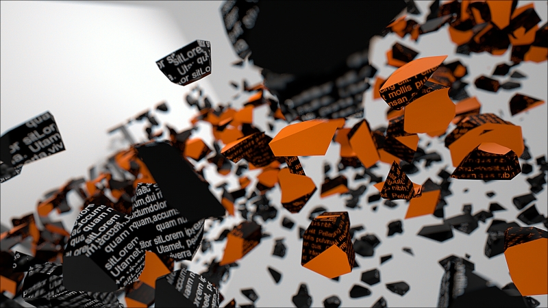
Using depth-of-field and chromatic aberration on the camera
After a few test renders, and a few more tweaks, we're ready to render the entire animation:
Launch the Render Settings window.
In the Output options, set the Frame Range option to what you'd like to render for your animation. If you'd like to render your entire timeline, change the Frame Range option to All Frames.
In the Save option for the Render Settings, enter or browse to the file path you want to render your frames to.
In the Save options, you can also set other options for the format of the rendered frames.
Now, hit render!
Render your animation. We're just going to render locally for now (on one machine). Use the Render to Picture Viewer command, either through the top Command palette or through the main menu (Render | Render to Picture Viewer).
In this section, we covered a lot of material very briefly. Any single aspect of the scene we've just created could be covered in extensive detail. Hopefully, this has provided you with a good start so that you can continue exploring all that Cinema 4D has to offer with more confidence.
Remember, if you have any questions about specific properties of an object, you can always find them in the help documentation.