

Architecture 0
Architecture is the set of strategic design optimization decisions for a system. Many different architectures can meet the same functional needs. What distinguishes them is their optimization criteria. One architecture may optimize worst-case performance, while another may optimize extensibility and scalability, and yet another may optimize safety, all while meeting the same functional needs.
The Harmony process has two primary components: the Harmony Agile Model-Based Systems Engineering process (Harmony aMBSE) and the Harmony for Embedded Software process (Harmony ESW). They each describe workflows, work products, practices, and guidance for combining agile and model-based engineering in their respective disciplines. See the author’s Real-Time Agility book for more details.
The Harmony process identifies five key views of architecture.
Subsystem and component view
This view focuses on the largest scale pieces of the system, and their organization, relations, responsibilities, and interfaces.
Concurrency and resource view
This view focuses on the concurrency units and management of resources within the system. Processes, tasks, threads, and the means for safely sharing resources across those boundaries are the primary concerns of this view.
Distribution view
This view focuses on how collaboration occurs between different computational nodes within the system and how the subsystems share information and collaboration. Communication protocols and middleware make up the bulk of this view.
Dependability view
The three pillars of dependability are freedom from harm (safety), the availability of services (reliability), and protection against attack (security).
Deployment view
Generally, subsystems are interdisciplinary affairs, consisting of some combination of software, electronic, and mechanical aspects. This view is concerned with the distribution of responsibility among the implementation of those disciplines (called facets) and the interfaces that cross engineering disciplinary boundaries.
Some recommendations for architecture in agile-developed systems are shown in Figure 1.29:
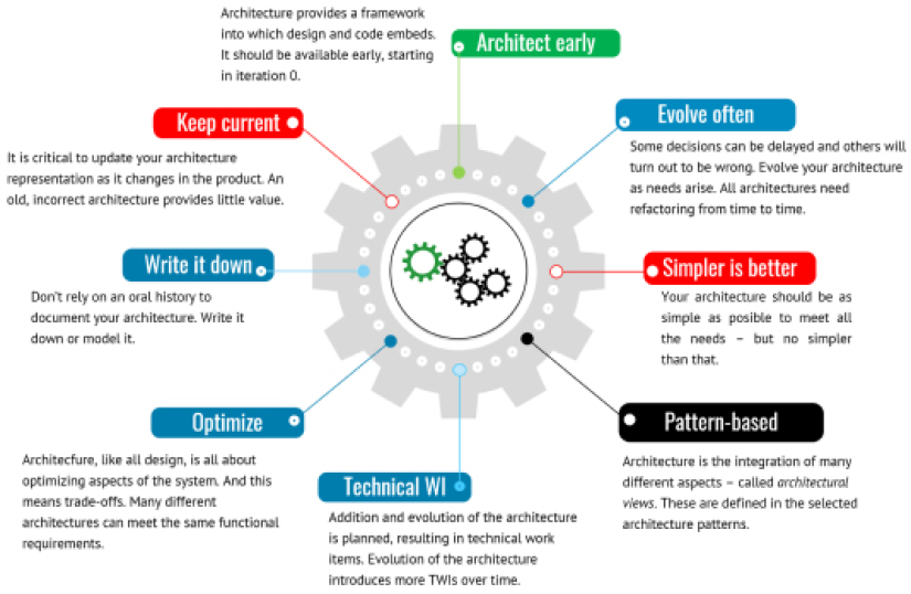
Figure 1.29: Agile architectural guidelines
Purpose
Because architecture provides, among other things, large-scale organization of design elements, as engineers develop those design elements, Architecture 0 provides a framework into which those elements fit. It is fully expected that Architecture 0 is minimalist, and therefore incomplete. It is expected that the architecture will change and evolve through the development process but it is an initial starting point.
Inputs and preconditions
A basic idea of the functionality and use of the system is necessary to develop the initial architectural concept. Thus, the preconditions for the development of Architecture 0 are the product vision and at least a high-level view of the epics, use cases, and user stories of the system.
Outputs and postconditions
The output is a set of architecture optimization criteria and an initial set of concepts from the different architectural views. This may be textual, but I strongly recommend this being in the form of a SysML architectural model. This model may have a number of different diagrams showing different aspects of the architecture. It is common, for example, to have one or more diagrams for each architectural view. In Architecture 0 many of these will be missing and will be elaborated on as the project proceeds.
How to do it
Architecture 0 is an incomplete, minimalist set of architectural concepts. Some thought is given to architectural aspects that will be given later, if only to assure ourselves that they can be integrated smoothly when they are developed. Again, it is expected that the architecture will be elaborated, expanded, and refactored as the product progresses.
Figure 1.30shows the basic workflow.
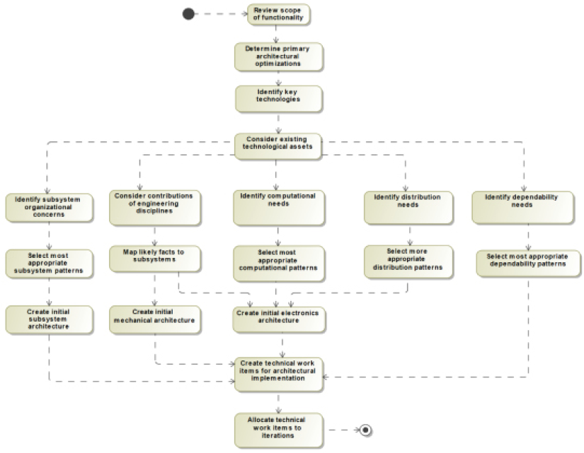
Figure 1.30: Architecture 0
Review the scope of functionality
Architectures must be fit for purpose. This means that while architectural decisions are largely about optimizations, the architecture must, first and foremost, achieve the functional needs of the system. This step reviews the essential required functionality that must be supported by the architecture.
Determine primary architectural optimizations
Selecting a design is an exercise in balancing competing optimization concerns making up the primary set of architectural goals. This step identifies and ranks the most important architectural considerations, such as worst-case performance, average performance, bandwidth, throughput, scalability, extensibility, maintainability, manufacturability, testability, and certifiability, to name a few.
Identify key technologies
It is common that one or more key technological ideas dominate the vision of the product. Electric cars, for example, have electric motors and electronic means to power them. While not necessarily defining the solutions here, it is important to at least identify the key technologies to constrain the solution space.
Consider existing technologies assets
Unless this is the very first time an organization has developed a similar product, there is likely some “prior art” that should be considered for inclusion in the new product. The benefits and costs can be considered as employing the organization’s existing technological intellectual property versus creating something entirely new.
Identify subsystem organizational concerns
Subsystems are the largest-scale pieces of the system and thus serve as the primary organization units holding elements of designs from downstream engineering. This step considers the pros and cons of different subsystem allocations and organizations. A good set of subsystems are:
- Coherent – provide a small number of services
- Internally tightly coupled – highly codependent elements should generally reside in the same subsystem
- Externally loosely coupled – subsystems should stand on their own with their responsibilities but collaborate in well-defined ways with other subsystems
- Collaborative with interfaces – interact with other subsystems in well-defined ways with a small number of interfaces
Consider contributions of engineering disciplines
The aspects of a design from a single engineering discipline is called a facet. There will typically be software facets, electronic facets, mechanical facets, hydraulic facets, pneumatic facets, and so on. The set of facets and their interactions are known as the deployment architecture, an important view of the system architecture. Early on, there may be sufficient information to engage engineers in these disciplines and consider how they are likely to contribute to the overall design.
Identify computational needs
Computational needs affect both software and electronics disciplines. If the system is an embedded system – the primary case considered in this book – then the computational hardware must be selected or developed with the particular system in mind.
These decisions can have a huge impact on performance and the ability of the software to deliver computational functionality. The software concurrency architectural concerns are not considered here, as they are solely a software concern. Nevertheless, the system must have adequate computational resources, and early estimates must be made to determine the number and type of CPUs and memory.
Identify distribution needs
Networks such as 1553 or CAN buses and other connection needs, as well as possible middleware choices including AUTOSAR, CORBA, and DDS, are the focus of this step.
Identify dependability needs
This step is crucial for safety-critical, high-reliability, or high-security systems. The initial concepts for managing dependability concerns must be considered early for such high-dependability systems and may be saved for later iterations in systems in which these are a minimal concern.
Select the most appropriate subsystem patterns
There are many organizational schemes for subsystem architecture, such as the layered pattern microkernel pattern, and channel pattern, that provide different optimizations. See the author’s book Real-Time Design Patterns for more detail on these patterns. The definition and use of patterns are discussed in more detail in Chapter 3, Developing Systems Architecture.
Map likely facets to subsystems
Facets are the contributions to an overall design from specific engineering disciplines, such as software, electronics, and mechanical engineering. We recommend that subsystem teams are interdisciplinary and contain engineers from all relevant disciplines. This step is focused on early concept deployment architecture.
Select the most appropriate computational patterns
Computational patterns concentrate on proposed computational approaches. While largely a software concern, electronics play a key role in delivering adequate computation power and resources. This is especially relevant when the computation approach is considered a key technology, as it is for autonomous learning systems or easy-to-certify cyclic executives for safety-critical systems.
Select the most appropriate distribution patterns
There are many ways to wire together distributed computing systems with networks, buses, and other communication links, along with supporting middleware. This architectural view focuses on that aspect of the system design. This impacts not just the software, but the electronic and, to a lesser degree, mechanical designs.
Select the most appropriate dependability patterns
Different patterns support different kinds of optimizations for safety, reliability, and security concerns. If these aspects are crucial, they may be added to Architecture 0 rather than leaving them for later design. Deciding to “make the product safe/reliable/secure” late in the development cycle is a recipe for project failure.
Create initial subsystem architecture
This aspect is crucial for the early design work so that the design elements have a place to be deployed. Subsystems that are not needed for early iterations can be more lightly sketched out than ones important for the early increments.
Create initial mechanical architecture
The initial mechanical architecture provides a framework for the development of physical structures, wiring harnesses, and moving mechanical parts.
Create initial electronic architecture
The initial electronics architecture provides a framework for the development of both analog electronics such as power management, motors, and actuators, as well as digital electronics, including sensors, networks, and computational resources.
Create technical work items or architectural implementation
A skeletal framework for the architecture is provided in Architecture 0 but beyond this, architectural implementation work results in technical work items that are placed in the backlog for development in upcoming iterations.
Allocate technical work items to iterations
Initial allocation of the technical work items is done to support the product roadmap and, if available, the release plan. These elements may be reallocated later as the missions of the iterations evolve.
Example
Review the scope of functionality
The Pegasus is a high-end smart cycling trainer that provides fine-grained control over bike fit, high-fidelity simulation of road feel, structured workouts, and interactions with popular online training apps. Read the content of Appendix A to review the functionality of the system.
Determine primary architectural optimizations
The primary optimization concerns in this example are determined to be:
- Recurring cost – the cost per shipped item
- Robustness – maintenance effort and cost-of-ownership should be low
- Controllability – fine-grained control of power over a broad range
- Enhance-ability – the ability to upgrade via Over-The-Air to add new sensors, capabilities, and training platforms is crucial
Identify key technologies
There are a number of key technologies crucial to the acceptance and success of the system:
- Low-energy Bluetooth (BLE) Smart for interacting with common sensors and app-hosting clients (Windows, iPad, iPhone, and Android)
- ANT+ for connecting to common sensors
- IEEE 802.11 wireless networking
- An electronic motor to provide resistance
These technologies are considered essential in this case, but we do want to take care not to overly constrain the design solution so early in the product cycle.
Consider existing technologies assets
This is a new product line for the company and so there are no relevant technological assets.
Identify subsystems organizational concerns
To improve manufacturability, we want to internalize cabling as well as minimize the number of wires. This means that we would like to co-locate the major electronics components to the greatest degree possible. However, user controls must be placed within convenient reach. Care must also be taken for adequate electric shock protection as the users are likely to expose the system to corrosive sweat.
Select the most appropriate subsystem patterns
We select the Hierarchical Control Pattern and Channel Pattern, from Real-Time Design Patterns, Addison-Wesley by Bruce Powel Douglass, 2003, as the most applicable for our systems architecture.
Create an initial subsystem architecture
Figure 1.31 shows the operational context of the Pegasus indoor training bike. This is captured in a Block Definition Diagram (BDD) in the architectural design package of the model. The operational context defines the environmental actors with which the architecture must interact during system operation:
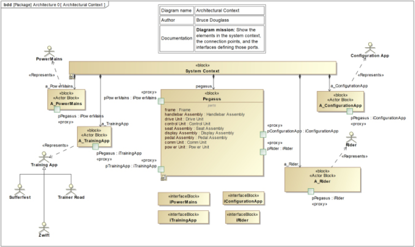
Figure 1.31: Pegasus context diagram
Figure 1.31 shows the elements in the Pegasus context. Note that we used blocks with the stereotype «Actor Block», each with a «represents» dependency to the actor they represent. This is done because in Cameo actors cannot have ports, and we wish to use ports to specify the interfaces used in the system context. These stereotypes are not defined in Cameo and so must be added in a user-created profile within the project.
Figure 1.32 shows how these elements connect in an internal block definition diagram owned by the System Context block:
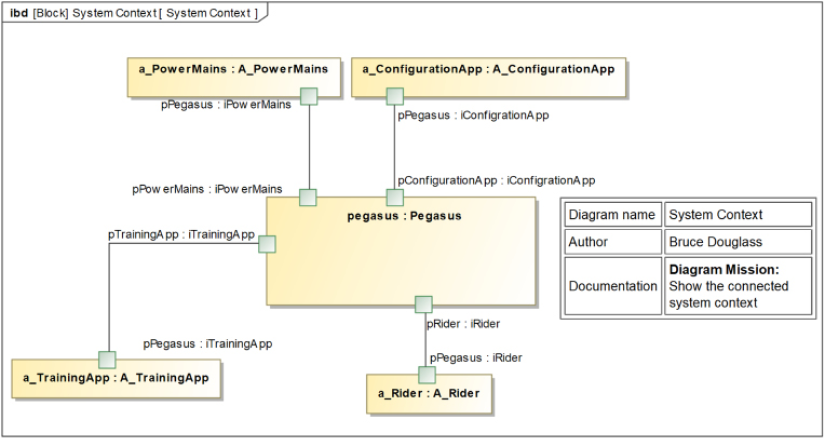
Figure 1.32: Pegasus connected context
Next, Figure 1.33 shows the set of subsystems. This diagram is like a high-level parts list and is very common in system designs in SysML:
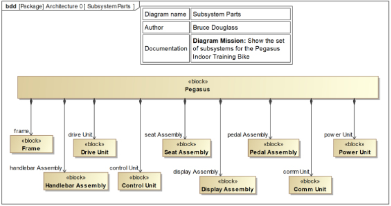
Figure 1.33: Pegasus subsystems
Perhaps more interesting is Figure 1.34, which shows how the subsystems connect to each other in an Internal Block Diagram (IBD). This is also a commonly used architectural view in SysML models. Specifically, this figure shows the primary functional or dynamic interfaces.
I follow a convention in my architectural models in which dynamic connections – that is, ones that support runtime continuous or discrete flow – use ports, but static connections – such as when parts are bolted together – as shown using connectors with the «static» stereotype. I find this a useful visual distinction in my systems architecture diagrams. Thus, the relation between the Frame and the Drive Unit is an association but the relation between the Pedal Assembly and the Drive Unit employs a pair of ports, as there are runtime flows between the pedals and the drive motor during system operation.
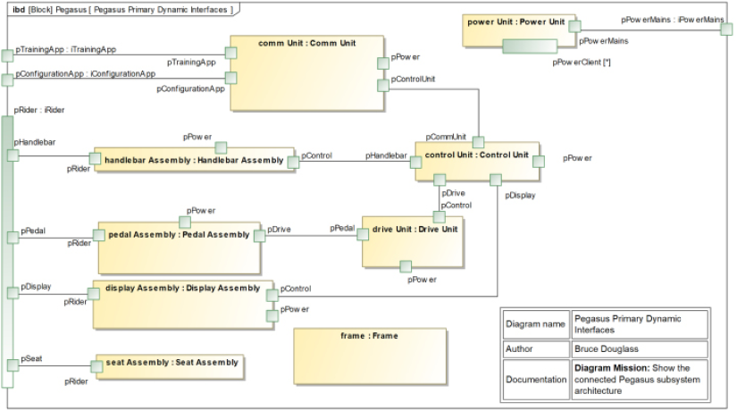
Figure 1.34: Pegasus connected architecture – Primary dynamic interfaces
Consider contributions of engineering disciplines
The electronics will provide the interfaces to the user for control of the trainer as well as physical protocols for app communication. It will also provide resistance via the application of torque from the electronic motor.
The mechanical design will provide the bike frame and all the bike fit adjustments. The pedals will accept torque from the user and provide resistance to applied force via the crank arms. Additionally, the weighted flywheel smooths out resistance by providing inertial load.
Finally, the mechanical design will provide all the cable routing.
The software will provide the “smarts” and use electronics to receive and process user input from controls, inputs from connected apps, as well as from the pedals. The software will also be responsible for messages to the apps for measured sensor data.
Map likely facets to subsystems
Facets, you will remember, are the contributions engineering disciplines provide to the system design. Table 1.11 shows the initial concept for mapping the engineering facets to the subsystem architecture. This will result, eventually, in a full deployment architecture, but for now, it just highlights our current thinking about the work from the engineering disciplines that will map to the subsystems.
|
Subsystem |
Mechanical |
Electronics |
Software |
|
Frame |
Mechanical only |
||
|
Handlebar assembly |
Mechanical only |
||
|
Drive unit |
Housing for motor, flywheel, and drive train |
Motor electronics |
Discrete outputs from control unit SW controlled |
|
Control unit |
Cabling and mounting |
Primary CPU, memory, and electronic resources for SW, persistence storage for SW |
Control motor, process incoming sensor and power data, process communications with apps, and Over-The-Air updates |
|
Seat assembly |
Mechanical only |
||
|
Display assembly |
Cabling and mounting |
Display and buttons, and USB connectors (future expansion) |
User I/O management and USB interface support |
|
Pedal assembly |
Crank arms, LOOK-compatible shoe mount, connects to drive train |
Power sensor in the pedal assembly |
Discrete inputs to SW in control unit |
|
Comm unit |
Cabling and mounting |
802.11, Bluetooth (BLE) Smart, and ANT+ |
SW in control unit controls and mediates communications from sensors and external apps |
|
Power unit |
Cabling and mounting |
Converts wall power to internal power and distributes where needed |
Table 1.11: Initial deployment architecture
Identify computational needs
At a high level, the primary computational needs are to:
- Receive and process commands to vary the resistance either from the internal load, user input, or app control
- Actively control the resistance provided by the motor
- Monitor connected Bluetooth and ANT+ sensors, such as from heart-rate straps
- Send sensor data to connected apps
- Update the user display when necessary
- Perform Over-The-Air updates
Select the most appropriate computational patterns
An asymmetric dual-processor architecture is selected with a single primary CPU in the Control Unit and a secondary processor to manage communications.
Identify distrubtion needs
All communications needs will be performed by a (proposed) 16-bit communication processor housed in the comm unit; all other SW processing will be performed by the control unit on the primary CPU.
Select the most appropriate distribution patterns
To facilitate the timely distribution of information within the system, an internal serial interface, such as RS232, is deemed adequate.
Identify dependability needs
The primary safety concern is electric shock caused by faulty wiring, wear, or corrosion. Reliability needs to focus on resistance to corrosion due to sweat, and the durability of the main drive motor. Security is determined to not be a significant concern.
Select the most appropriate dependability patterns
Single-Channel Protected Pattern is selected as the most appropriate.
Create initial electronic architecture
The power interfaces are shown in Figure 1.35:
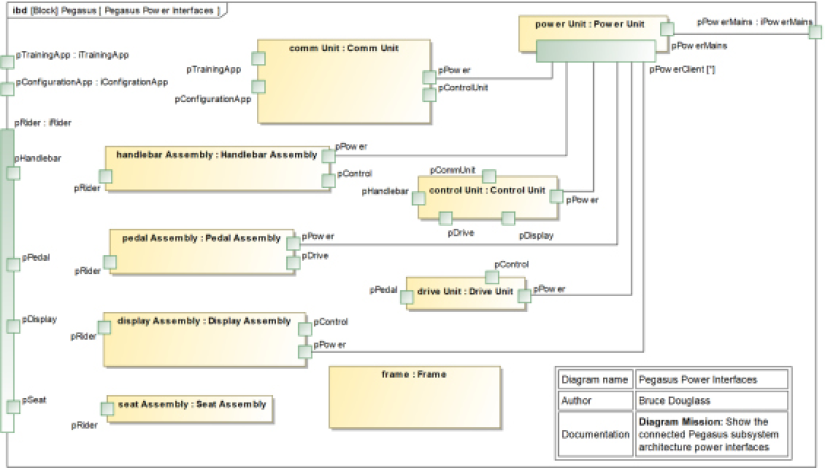
Figure 1.35: Pegasus connected architecture – Power interfaces
In addition, the drive unit hosts the primary motor to provide resistance to pedaling.
Create initial mechanical architecture
The internal mechanical connections are shown in Figure 1.36:
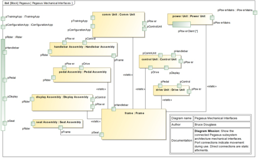
Figure 1.36: Pegasus connected architecture – Mechanical interfaces
The seat and handlebars are adjustable by the user and pedals can be added or removed, as well as providing a spot for the rider to “clip in” when they get on the bike. Thus, these connections use ports. The other connections are places where pieces are bolted together and do not vary during operation, except under catastrophic mechanical failure, so connectors represent these connections.
Create technical work items for the architectural implementation
We identify the following technical work items in Architecture 0:
Mechanical technical work items:
- CAD frame design
- Hand-built frame
- Factory built frame
Electronic technical work times:
- Motor simulation platform
- Hand-built motor
- Factory-built motor electronics
- CPU selection
- Simulated digital electronics platform
- Hand-built digital electronics platform
- Factory-built digital electronic platform
Allocate technical work items to the iterations
Allocation of such technical work items is discussed in detail in the Iteration plan recipe.
Additional note
Note that this is not a fully fleshed-out architecture. We know that in principle, for example, the pedals and the drive unit have flows between them because the pedals must provide more resistance when the main motor is producing greater resistance, but we don’t know yet if this is a mechanical power flow perhaps via a chain, an electronic flow, or discrete software messages to active resistance motors at the site of the pedals. I added a power interface to the Pedal assembly. If it turns out that it isn’t needed, it can be removed. That’s a job for later iterations to work out.
I also didn’t attempt to detail the interfaces – again, deferring that for later iterations. But I did add the ports and connectors to indicate the architectural intent.