

Managing change
In real engineering environments, work products are not the result of a single person working in isolation. Rather, they represent the integration of the efforts of many people. In model-based systems engineering, the model is central to the project and this means that many people must work simultaneously on the model. Without getting in each other’s way. Or losing work.
The heart of managing such a shared engineering work product is change management and its close cousin configuration management. The former is the process and procedures that govern how changes made to a work product are controlled, including the controlled identification of changes, the implementation of those changes, and the verification of the changes. Configuration management is a systems engineering process for establishing and maintaining consistency of a product’s performance, functional, and physical attributes with its requirements, design, and operational information throughout its life.
See https://en.wikipedia.org/wiki/Configuration_management for more information. Both of these are deep and broad topics and will be treated somewhat superficially here. It is nevertheless an important topic, so we will present a simple workflow for change and configuration management of models in this recipe.
Central to this recipe is the notion that we change a model for a purpose. In traditional engineering processes, this is managed via a change request, sometimes called an Engineering Change Order (ECO). In agile processes, this is due to a work item in the iteration backlog. In either case, the change is made to the model for a reason and to achieve some goal. The problem is that many people need to change other elements in the model to achieve other goals. Frequently, different changes must be made by different people to the same model elements.
The concept of a package was introduced early in the development of UML. A package is a model element that contains other model elements, including use cases, classes, signals, behaviors, diagrams, and so on. As such, it is the fundamental unit of organization for models. It was also intended to be the fundamental Configuration Item (CI), the atomic piece for configuration management. It was envisioned that a modeler would manage the configuration of a package as a unit, including all its internal contained elements together. Modern tools like Cameo and Rhapsody support this but also allow finer-grained configuration management down to the individual element level, if desired. Nevertheless, the package remains the most common CI.
The terms version and revision are common terms in the industry around this topic. A model version is a changed model. Such changes are typically considered minor. A revision is a controlled version and is generally considered a major change. It is common that revisions are numbered as whole numbers and versions are fractional numbers. Version 19.2 indicates revision 19 version 2. Revisions are considered baselines and permanent, and versions are minor changes and temporary. Revisions generally go through a more robust verification and validation process, often at the end of a sprint. Versions may be created at each test-driven development cycle (known in the Harmony process as the nanocycle – see the Test-Driven Modeling pattern in Chapter 5, Demonstration of Meeting Needs) and so come and go rapidly.
All this is relevant to the two basic workflows for change and configuration management: Lock and Release and Branch and Merge. Both primarily work at the package level.
Purpose
The purpose of this recipe is to provide a workflow for robust change control over model contents in the presence of multiple and possibly simultaneous changes to the model made by different engineers.
Inputs and preconditions
This recipe starts after a model is baselined. A baseline means that the model is stored under a configuration and change control environment, usually after it has achieved some basic level of maturity. This means that there is a current source of truth for the model contents, and all changes are managed by the configuration and change control environment. The second precondition is the presence of a change to be made to the model. This recipe does not concern itself with how the decision is made to proceed with the change, only that the decision has been made.
Outputs and postconditions
The output is the updated model put back under configuration and change control either as a version or as a revision, depending on the scope of the change.
How to do it
Figure 1.45 shows the workflow for this recipe. Two alternative flows are shown. On the left is the more common and simpler Lock and Release sub-workflow, and on the right is the Branch and Merge sub-workflow. Both sub-workflows reference the Make Change activity, which is shown as a nested diagram on the right of the figure:
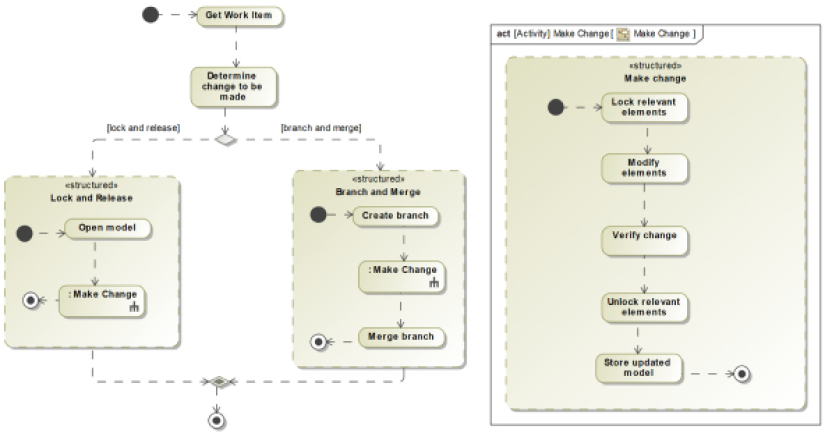
Figure 1.45: Managing change
Get work item
The start of the workflow is to get a request to modify the baseline model. This can be the addition of a model structure, behavior, functionality, or some other property. It can also be to repair an identified defect or pay off some technical debt.
Determine the change to be made
Once the request for change has been received, the engineer generally develops a plan for the modification to be made. The work may involve a single element, an isolated set of elements in the same package, or broad, sweep changes across the model.
Lock and release
The Lock and Release workflow is by far the most common approach to modifying a model under configuration control. The detailed sub-tasks follow. Its use means that other engineers are prohibited from making changes to the elements checked out to the first engineer, until the locks owned by the latter are released.
Open the model
This step opens the model in the configuration management repository.
Make a change
This makes and verifies the change in the model. It has a number of sub-tasks, which will be described shortly.
Branch and merge
This alternative sub-workflow is useful when there are many people working on the model simultaneously. People will create a separate branch in which to work so that they will not interfere with anyone else’s work. The downside is that it is possible that they will make incompatible changes, making the merge back into the main trunk more difficult. This sub-workflow has three steps.
Create a branch
In this step, the engineer creates a branch of the main project; this latter model is known as the trunk. A branch is a separate copy of the project completely independent of the original, but containing, at least at the start, exactly the same elements.
Merge a branch
This step takes the changes model and merges those changes back into the main project or trunk. There are usually changes that are merely additions but other changes may be in conflict with the current version of the trunk, so this step may require thoughtful intervention.
Make a change activity
This activity is referenced in both the Lock and Release and Branch and Merge sub-workflows. It contains several included steps.
Lock relevant elements
Whenever you load a model that is under configuration control, you must explicitly lock the elements you wish to modify.
Modify elements
This step is where the actual changes to the model are performed.
Verify change
Before checking in a changed model, it is highly recommended that you verify the correctness of the changes. This is often done by performing tests and a review/inspection of the model elements. Recipes in Chapter 5, Demonstration of Meeting Needs, discuss how to perform such verification.
Unlock relevant elements
Once the changes are ready to be put back into the configuration management repository, they must be unlocked so that other engineers can access them.
Store updated model
In this final step of the Make Change Activity, store the unlocked model back into the configuration management repository.
Example
Since we are using Cameo in this book, we will be using Cameo Teamwork Cloud as the configuration management environment. Other tools, such as Rhapsody from IBM, can use various configuration management tools but with Cameo, either Teamwork Cloud or the older Teamwork Server is required.
Because the more common Lock and Release workflow is a degenerative case of the more elaborate Branch and Merge sub-workflow, we will just give an example of the latter.
The example here shows a context for an exercise bike. The context block is named Pain Cave, and it contains a Rider part that represents the system user, and an Exercise Bike part that represents the system under design. The Rider block provides cadence and power as inputs to the system as flow properties and receives resistance back:
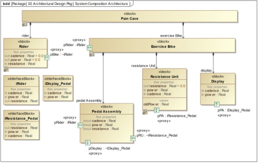
Figure 1.46: Pain cave model composition architecture
Figure 1.47 shows the internal block diagram connecting the Rider and Exercise Bike parts in the context of the Pain Cave, while Figure 1.48 shows the internal structure of the Exercise Bike itself:
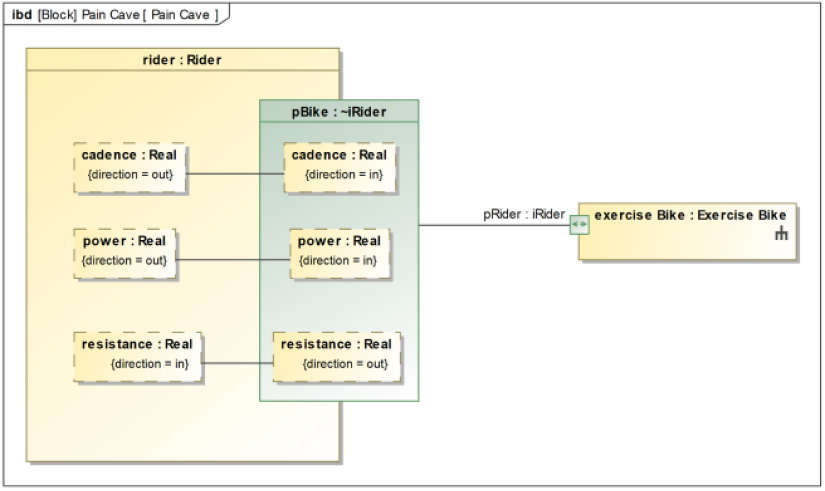
Figure 1.47: Pain cave connected context
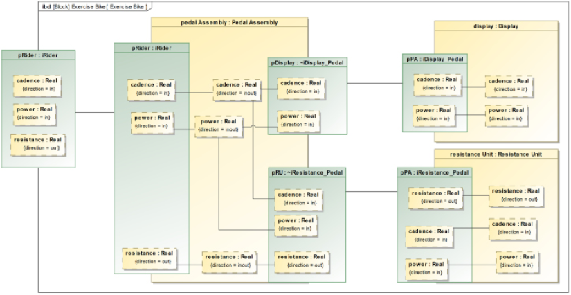
Figure 1.48: Exercise bike connected architecture
Finally, Figure 1-49 shows the behaviors of two elements, Rider and Resistance Unit. The concept here is that the Resistance Unit produces resistance based on the power and cadence it receives from the Rider. Of course, this behavior performed is not in any way realistic but just a simple example of behavior:
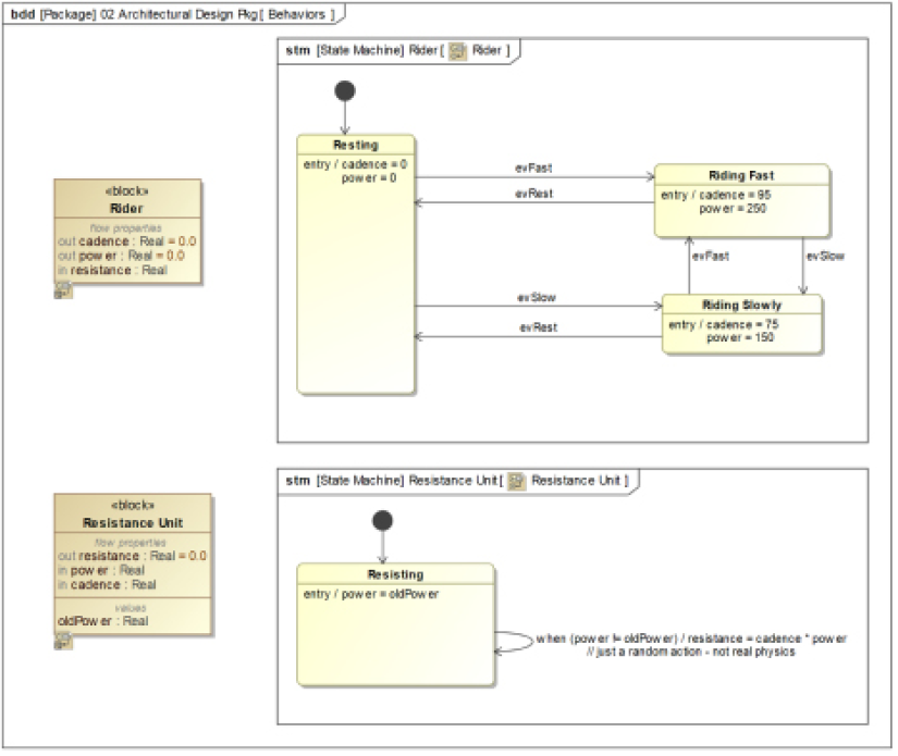
Figure 1.49: Behaviors
This system does execute, as can be seen in Figure 1.50, which shows the current states of the running simulation using Cameo’s Simulation Toolkit, and the current values of the flow properties in Figure 1.51. In Cameo, you can visualize a running system in a number of ways, including the creation of diagrams that contain other diagrams; for activity and state diagrams, Cameo highlights the current state or action as it executes the model. The Simulation Toolkit also exposes the current instances and values held in value properties during the simulation:
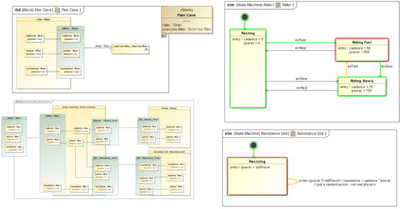
Figure 1.50: Pain cave simulation view
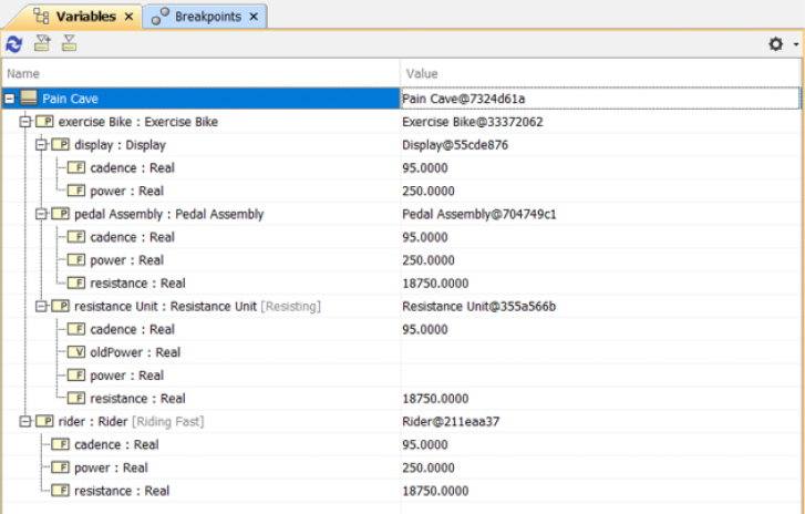
Figure 1.51: Pain cave values during simulation
Get work item
For this example, we will work on two user story work items together:
- As a rider, I want to be able to see the pedal cadence and power as I ride so that I can set my workout levels appropriately.
- As a Rider, I want to be able to control the amount of resistance, given cadence, and power so I have finer control over my workout efforts.
Determine the change to be made
In this simple example, the changes are pretty clear. The Display block must be able to get input from the Rider to change the scaling factor for the resistance, and then send this information to the Resistance Unit. The Resistance Unit must incorporate the scaling factor in its output. Additionally, behavior must be added to the Display block to display cadence and power.
Create branch
In the Cameo tool, after logging in to the Teamwork Cloud environment, select your project using Collaborate > Projects menu to select your project. At the right of the project from which you want to create a baseline, click on the ellipsis to open the Select Branch dialog, then select Edit Branches, which opens the Edit Branches dialog. Here, select the version from which you wish to branch and select Create Branch. These dialogs are all shown in Figure 1.52:
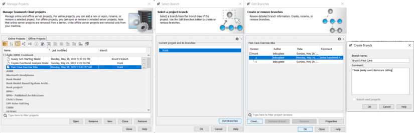
Figure 1.52 Creating a branch
Once created, you can open the branch in the Manage Projects dialog.
Make Change::Lock relevant elements
To edit the elements you must lock them. In Cameo, this is a right-click menu option for elements in the containment tree. We will work exclusively in the 02 Architectural Design Pkg package, so we will lock that package and all its contents. In Cameo, you must select Lock Elements for Edit Recursively to lock the package and the elements it contains. If you lock without recursion, you only have edit rights to the package itself and not its content.
Make Change::Modify elements
Let’s look at the changes made for each of the work items:
- As a rider, I want to be able to see the pedal cadence and power as I ride so that I can set my workout levels appropriately.
For this change, we’ll modify the Display block to have a state behavior driven by a change event, whose specification is when either the power or the cadence changes. This requires the addition of a couple of value properties. The Display state machine is shown in Figure 1.53. For our purposes here, we’ll just use Groovy print statements to print out the values. In the simulation, these print statements output text to the console of the Simulation Toolkit:
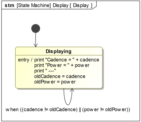
Figure 1.53: Display state machine
- As a Rider, I want to be able to control the amount of resistance, given cadence, and power.
For this work item, we’ll need to add a pair of ports between the Rider and the Resistance Unit blocks so the Rider can send the evAugmentGear and evDecrementGear events. The Rider state machine will be extended to be able to send these events (under the command of the simulation user), and the Resistance Unit state machine will accept these events and use them to update the scaling factor used to compute resistance. We will also need to add said scaling factor and update the computation.
Figure 1.54 shows the updated Rider state machine and Figure 1.55 shows the updated Resistance Unit state machine. The latter state machine was refactored a bit to account for the issue that you also want to recompute the resistance when the gearing is changed, as well as when cadence or power changes:
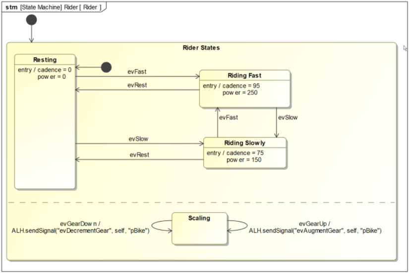
Figure 1.54: Updated rider state machine
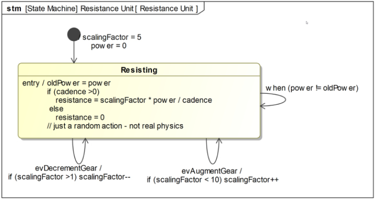
Figure 1.55: Updated resistance unit state machine
The updated block definition diagram is shown in Figure 1.56. Note the changes to the interface block iRider, the addition of a new port, and the value property for the Resistance Unit:
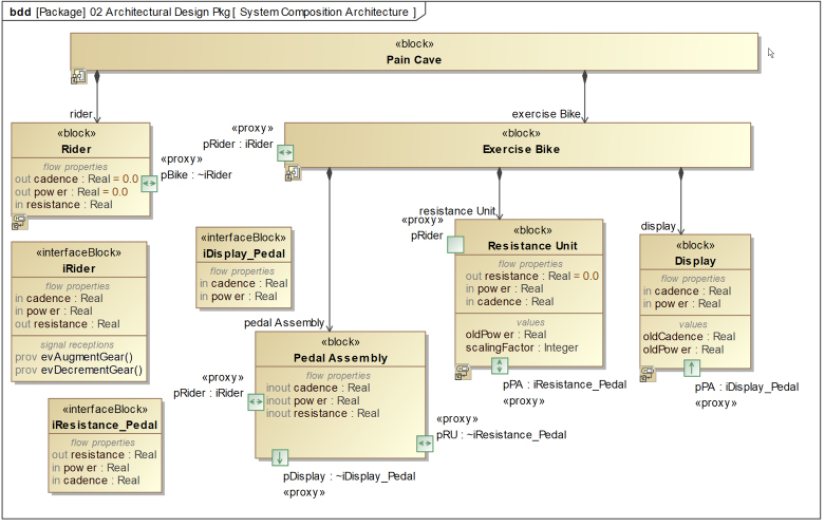
Figure 1.56: Updated pain cave BDD
Lastly, Figure 1.57 shows the updated internal block diagram for the Exercise Bike. Note that the Exercise Bike.pRider port is now also connected to the pRider port of the Resistance Unit. This allows the latter to receive the gearing events:
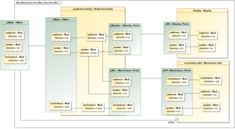
Figure 1.57: Updated exercise bike IBD
Make Change::Verify change
To make sure we made the changes correctly, we can run the simulation. As a simulation operator, you can use the simulation toolkit to start the operation sending the evFast signal to the Rider, and then send the evGearUp and evGearDown events to see the effect on the resulting resistance. Also, you can check the output console to ensure the cadence and power are being displayed.
Cameo makes it simple to create a simulation view that allows visualization of the behaviors (see Figure 1.58). I’ve superimposed the console window in the figure so you can see the results of the Display block behavior:
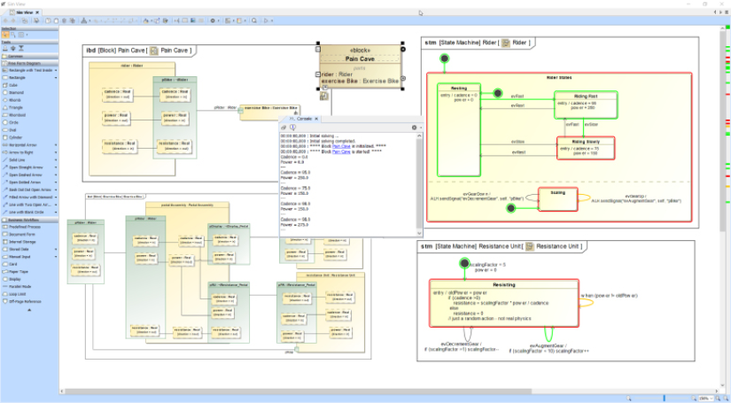
Figure 1.58: Exercise bike verification via simulation
Make Change::Unlock relevant element
Having made and verified the changes, we can save the changes. Right-click the package in the containment tree, and select Lock > Unlock elements recursively. This will open the Commit Project to Server dialog.
Make Change::Store the updated model
In the Cameo tool, unlocking the elements also stores them in the Teamwork Cloud repository, so this step is done.
Merge a branch
We now have a baselined and unmodified trunk version and our updated branch version. The last step is to merge our branch changes into the baseline.
In Cameo, open the trunk (target) model, then select Collaborate > Merge From; this opens the Select Server Project dialog. Here, select the branch version you just created:
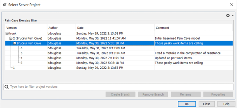
Figure 1.59: Selecting the branch for merge
Then a dialog pops up if you want to merge with the trunk locked or not. Always merge with the trunk locked.
Once you click on Continue, the Merge dialog opens. There are many options for seeing what the changes are, accepting some changes, and rejecting others. Color coding identifies the different kinds of changes: addition, deletions, and modifications:
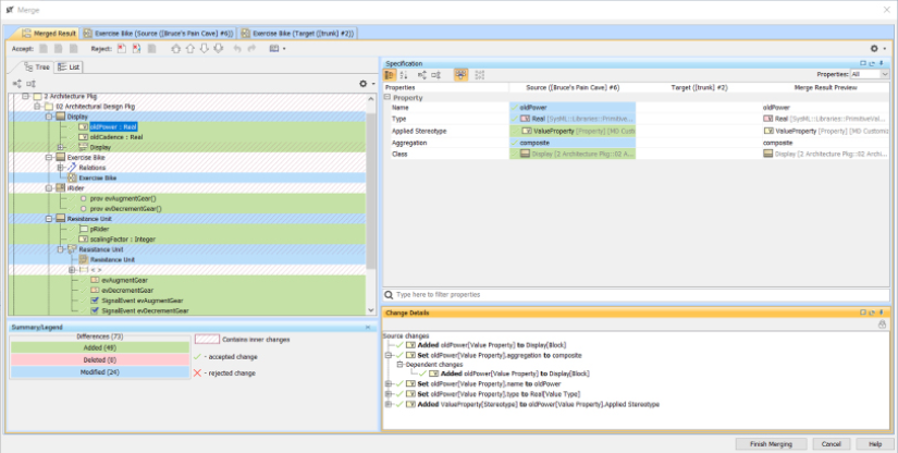
Figure 1.60: Review merge changes
Any conflicting changes are highlighted and can be resolved manually, by right-clicking and accepting either the source (updated branch) change or keeping the target (trunk) version of the element. Cameo has a nice feature that allows you to explore diagrammatic changes graphically. The scroll bar at the bottom of the window allows you to switch between the unchanged and changed views of the diagram.
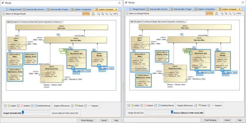
Figure 1.61: Reviewing diagrammatic changes
Click Finish Merging when you’re ready to complete the merge process and click Collaborate > Commit Changes to save the updated merged model to the trunk. Remember that the Branch and Merge approach is the lesser-used workflow, and the simpler Lock and Release approach is more common. Just remember to lock and unlock elements recursively and be sure to unlock when you’re done making your changes.
Join our community on Discord
Join our community’s Discord space for discussions with the author and other readers:
