-
Book Overview & Buying
-
Table Of Contents

Robotics at Home with Raspberry Pi Pico
By :
Robotics at Home with Raspberry Pi Pico
By:
Overview of this book
The field of robotics is expanding, and this is the perfect time to learn how to create robots at home for different purposes. This book will help you take your first steps in planning, building, and programming a robot with Raspberry Pi Pico, an impressive controller bursting with I/O capabilities. After a quick tour of Pico, you’ll begin designing a robot chassis in 3D CAD. With easy-to-follow instructions, shopping lists, and plans, you’ll start building the robot. Further, you’ll add simple sensors and outputs to extend the robot, reinforce your design skills, and build your knowledge in programming with CircuitPython. You’ll also learn about interactions with electronics, standard robotics algorithms, and the discipline and process for building robots. Moving forward, you’ll learn how to add more complicated sensors and robotic behaviors, with increasing complexity levels, giving you hands-on experience. You’ll learn about Raspberry Pi Pico’s excellent features, such as PIO, adding capabilities such as avoiding walls, detecting movement, and compass headings. You’ll combine these with Bluetooth BLE for seeing sensor data and remotely controlling your robot with a smartphone. Finally, you’ll program the robot to find its location in an arena.
By the end of this book, you’ll have built a robot at home, and be well equipped to build more with different levels of complexity.
Table of Contents (20 chapters)
Preface

Part 1: The Basics – Preparing for Robotics with Raspberry Pi Pico
 Free Chapter
Chapter 1: Planning a Robot with Raspberry Pi Pico
Chapter 2: Preparing Raspberry Pi Pico
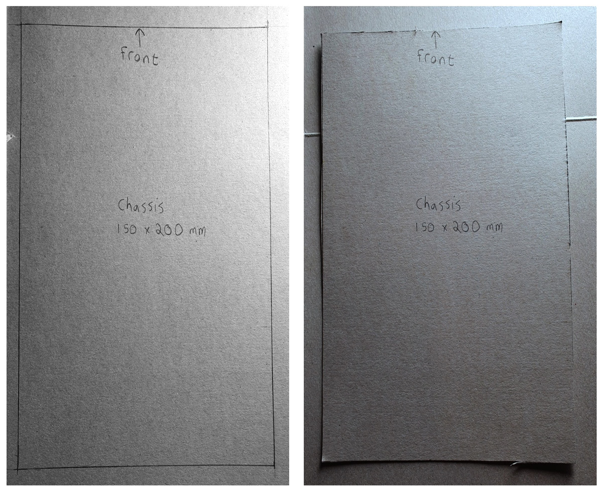
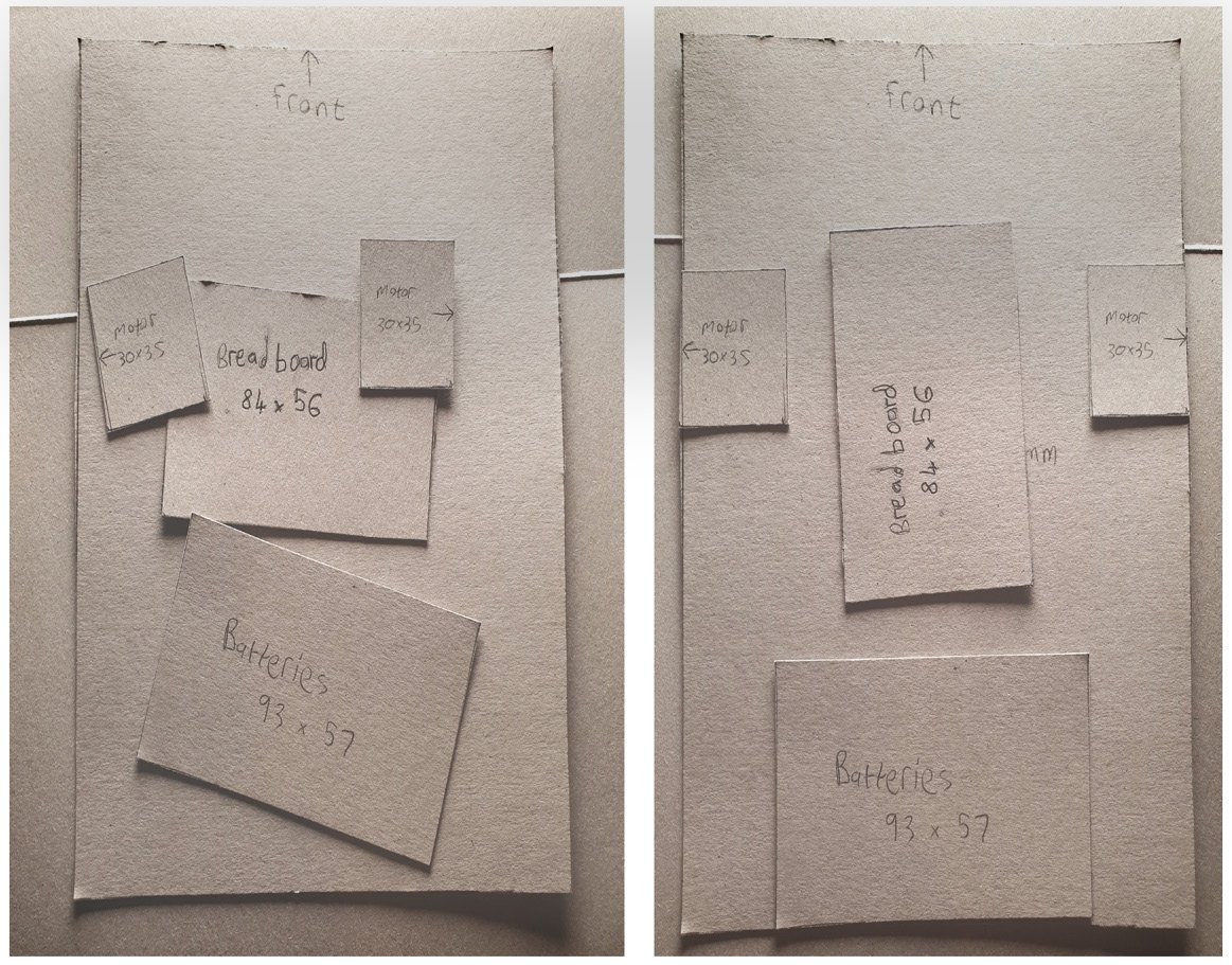
Chapter 3: Designing a Robot Chassis in FreeCAD
Chapter 4: Building a Robot around Pico
Chapter 5: Driving Motors with Raspberry Pi Pico
Part 2: Interfacing Raspberry Pi Pico with Simple Sensors and Outputs
Chapter 6: Measuring Movement with Encoders on Raspberry Pi Pico
Chapter 7: Planning and Shopping for More Devices
Chapter 8: Sensing Distances to Detect Objects with Pico
Chapter 9: Teleoperating a Raspberry Pi Pico Robot with Bluetooth LE
Part 3: Adding More Robotic Behaviors to Raspberry Pi Pico
Chapter 10: Using the PID Algorithm to Follow Walls
Chapter 11: Controlling Motion with Encoders on Raspberry Pi Pico
Chapter 12: Detecting Orientation with an IMU on Raspberry Pi Pico
Chapter 13: Determining Position Using Monte Carlo Localization
Chapter 14: Continuing Your Journey – Your Next Robot
Index