Let’s now take a look at the major components of both the Arduino IDE and the Arduino Uno board. After that, we will be ready to set everything up and write, transmit, and run our first Arduino program.
The Arduino IDE
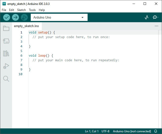
The Arduino IDE is free and open source software available for Windows, macOS, and Linux systems. Arduino also offers a web-based version that works in your web browser and stores your files in the cloud as opposed to locally. The examples in this book assume that you are using a locally installed version of the IDE on a Windows computer, but most steps will be identical, or at least very similar, across the three systems. In September 2022, the Arduino IDE received a major upgrade from version 1.8 to version 2.0. Version 2.0 is easier to use and more powerful, which means that now is a better time than ever to start using Arduino!. Figure 1.3 shows how the Arduino IDE 2.0.3 looks on startup:
Figure 1.3 – The Arduino IDE right after launch
We will take a closer look at the Arduino IDE later in this chapter after we have set it up, but for now, let us understand what the key components and the purpose of this IDE are:
- A text editor lets you write your C/C++ program right in the IDE. In Arduino parlance, programs are called sketches, a nod to the IDE’s origins in the Processing project (https://processing.org/). The editor has some useful features, such as syntax highlighting, auto-formatting, and auto-completion. However, it is a pretty simple editor still. While this simplicity is intentional, it is not as powerful as other modern code editors, such as Visual Studio Code, for example. There are more advanced alternatives to the built-in text editor, but for the purpose of this book, we will be using the IDE’s text editor as it is the most seamless option to develop Arduino programs.
- A compiler lets you translate your code to machine language for the microcontroller you are using. Arduino makes using the compiler very easy; all it requires is one click on the checkmark button in the top-left corner. When the compiler runs, it produces some output in the console window that appears under the editor window. This output can be very useful for troubleshooting your program.
- A programmer lets you seamlessly transfer the compiled machine code to your Arduino board that is connected to your PC via USB. All it takes is, again, one click on the arrow symbol in the top-left corner. And just like the compiler, the programmer will generate some output in the console under the editor that is useful for troubleshooting if the programming does not work as expected.
- A debugger lets you run your code step by step on the Arduino’s microcontroller. This advanced feature can be very useful for finding problems that happen during program execution. However, the debugger only works with certain boards (not with the Arduino Uno) and may require additional hardware, depending on the board. If a compatible board is connected, the Play button with the little bug in the top-left corner of the Arduino IDE becomes available to start a debugging session.
- A serial monitor lets you send text from the PC to the Arduino and can display text that your Arduino sends to the PC. This works with all boards and is an incredibly useful tool for debugging and interacting with your running program. The IDE also provides a serial plotter that can display multiple lines of numeric data sent from your Arduino board as a 2D live plot. The buttons to start the serial plotter and the serial monitor are located in the top-right corner of the IDE.
- Built-in hardware abstraction libraries make your code more or less independent of the board you are working with. This feature is not really visible on the surface, but it might be the most important one. This is what allows you to program even complex Arduino boards without having to look at the datasheet of the microcontroller, and to use the exact same code that you developed for one board across many different Arduino boards.
Now that we have a good understanding of what the Arduino IDE is, let’s look at the other aspect of the Arduino ecosystem: one of the boards that can be programmed with the Arduino IDE.
The Arduino Uno
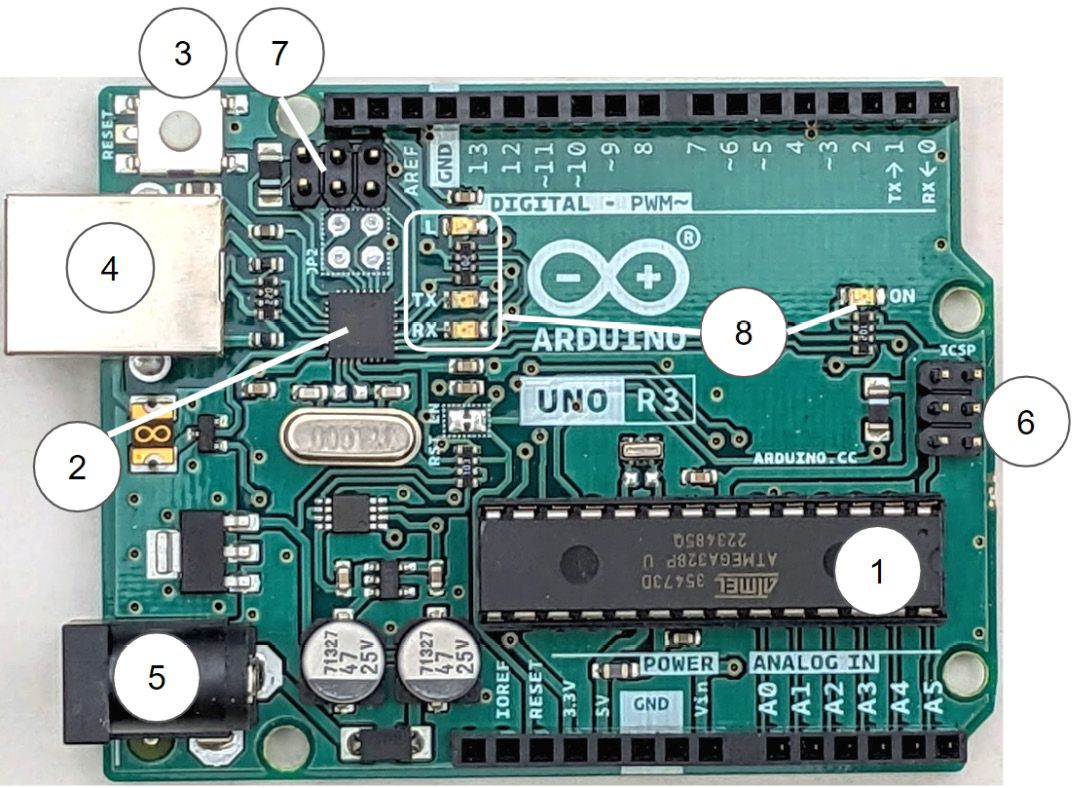
The Arduino Uno is the most widely used Arduino board due to its simplicity, ruggedness, and widespread availability. It is built around the ATmega328P microcontroller, which has a long history in low-cost DIY electronics projects. The Uno is a great board to get started with Arduino as it is low-cost and simple, yet it contains all the key functionalities of a microcontroller board and is very forgiving to wiring and other mistakes that might damage more complicated boards. Similar to what we did for the IDE, let us look at the key components of the board and what their functionalities are. We will go a little more into detail here since we will rely on a solid understanding of the board components in future chapters. Figure 1.4 shows the Arduino Uno R3 board for reference:
Figure 1.4 – The Arduino Uno Rev3 microcontroller board
The key components that we will discuss next are labeled with numbers.
Main electronic components
The biggest chip on the board is the ATmega328P microcontroller (1). It is so big because it is enclosed in a socketed Dual Inline Package (DIP) housing, which allows you to replace it in case it gets damaged. This is the microcontroller that we will be programming toward the end of this chapter, and that controls all the output pins that you see lined along the bottom and top edges of the board. Let us call it the main microcontroller. It only needs very few peripheral components to run, namely the two small ceramic capacitors under and above it, and the little oscillator above it (under the R3 marking).
The second-largest chip on the board is another microcontroller, an ATmega16U2 microcontroller in a much smaller package that is soldered directly to the board (2). It comes pre-programmed with special firmware that lets it act as an interface between the USB connector and the ATmega328P. More technically, it implements a USB-to-serial converter. Let’s call this one the programmer. When we click the program button in the IDE, our computer starts communicating with this chip over USB, transmitting the compiled machine code to it. The programmer receives the code byte-by-byte over USB and transmits it to the main microcontroller over a serial interface. To enable this type of programming, there is a special bit of software already programmed into the main microcontroller, called the bootloader. We do not need to go into any more detail here about how the bootloader works. But it is worth mentioning that if you ever want to replace the main microcontroller, you need to either purchase one that is already pre-programmed with the Arduino bootloader or flash the Arduino bootloader onto it yourself.
There is a small RESET button in the top-left corner of the board (3). Pressing this button causes the main microcontroller to reset. It will stop the current program execution and start executing the program from the start, similar to rebooting a PC. The reboot of a microcontroller happens almost instantly. The reset button is typically not used very often, but it can be useful in the development process when you want to run your program from the start again to test something, or when the program has unexpectedly halted, and you need to reset it.
Below the reset button is the USB connector (4). On the Uno, this is a male USB Type-B port. Although this is a dated connector by now, it has the advantage of being very rugged and hard to damage. Smaller or third-party Arduino boards often have more modern Mini, Micro, or Type-C USB connectors.
Note
The Arduino can run on power provided by the USB port. However, if you use the Arduino’s 5V to power other consumers such as motors or long LED strips, you might exceed the 2.5 W of power that a USB port can provide. In this case, your PC will likely shut down the power to this port to protect itself from overcurrent. In the worst case though, damage to the PC’s USB port can occur.
The power connector for external power as well as the board’s power system is in the bottom-left corner (5). You can power the board through this connector with a voltage ranging from 7V to 12V, from a 2-cell lithium battery, for example. Directly above this connector is the linear voltage regulator that turns this input voltage into 5V, which is needed to run the microcontrollers. It is worth noting that this is not a very efficient kind of converter and can get hot quickly, depending on the power requirement of your project. In general, it is better practice to use a more efficient switched 5V regulator between the battery and your Arduino and connect its 5V output directly to the pin on your Arduino that is marked 5V. This way, you circumvent the onboard linear regulator altogether. We will investigate this and other power considerations in more detail in a later chapter.
There are 2 male 3x2 pin headers on the board. The one on the right (6) is labeled ICSP, which stands for In-Circuit Serial Programming. This is primarily a low-level programming port that can be used to flash the bootloader onto the main microcontroller. Beyond that, it can be used to access the SPI interface of the main microcontroller. The other male pin header is the ICSP interface for the programmer microcontroller (7). This is used to flash the USB-to-serial firmware onto the programmer during the production of the board. We will not need to use this interface.
There are two rows of female pin headers along the top and the bottom edge of the board. These pins are your Arduino’s interface to the world! This is where we connect all the physical components such as sensors, motor drivers, LEDs, displays, buttons, or potentiometers that we want to interact with. Very conveniently, the pins are all grouped by their function and labeled, making it easy for us to reference specific pins in our code (without having to look up anything in the datasheet of the microcontroller). Let us now look at the various groups of pins and their functions.
Power pins
As the name suggests, the POWER pins have to do with the power system of the board rather than with logical inputs and outputs. Going from left to right, they are as follows:
- IOREF: This is a 5V pin that is meant to signal to specialized connected boards (called Arduino shields) what voltage the Arduino board is running on.
- RESET: This pin is connected to the reset line of the microcontroller, which is internally pulled high by a large resistor. Connecting this pin to GND has the same effect as pressing the RESET button, effectively rebooting the main microcontroller.
- 3.3V: This is an output pin that provides 3.3V from a very small internal linear regulator. It can be used to power small peripherals that require 3.3V, but it is again better practice to not rely on it but to use an external switched 3.3V regulator instead.
- 5V: This pin connects directly to the 5V net of the board. It can be used to tap off 5V power for other components of your robot when the Uno is powered by the USB connector or the external power input. Or it can be used to power the Uno from a 5V source, such as an external 5V regulator.
- GND: These pins provide access to the board reference potential (ground). In general, every component that we want to connect to our Arduino needs to share the same reference potential and must therefore be connected to the Arduino’s GND net. This is why the Uno has three GND pins. In practice, though, this is often not enough, and we will learn how we can use a solderless breadboard to get even better access to GND.
- Vin: This pin is directly connected to the barrel connector in the bottom-left corner of the board. It can be used for the same purpose – to power the board from a battery or other voltage source in the range from 7V to 12V (with the caveat of relying on the inefficient onboard linear regulator).
On the left side of the top pin header is the AREF pin. It can be used to feed in an external reference voltage to Arduino Uno’s built-in analog-to-digital converter (ADC). By default, the ADC uses 5V as the voltage reference, which is acceptable for most applications, so the AREF pin is rarely used in practice.
GPIO pins
All other pins that are neither POWER pins nor AREF are General Purpose Input/Output (GPIO) pins and can be used as DIGITAL inputs and outputs. However, most pins of a microcontroller can be used for more than one functionality, depending on their configuration. To avoid confusion and simplify things a little, only pins 0 to 13 on the Arduino are labeled as DIGITAL. These digital pins can be used to either read digital input signals as HIGH or LOW (for example, from a push button), or to send a single bit of information (for example, to control a LED) by setting their output voltage to HIGH (5V) or LOW (GND). Some of the DIGITAL pins have a tilde in front of their pin number. This indicates that they can be used to send a PWM signal. This means we can ask them to automatically go HIGH and LOW repeatedly at a very high frequency, and we can easily control the width of the high pulse (from 0%, always LOW, to 100%, always HIGH). This capability is useful to control the brightness of LEDs, the speed of DC motors, or the position of RC servos, for example. Lastly, pins 0 and 1 are marked as RX and TX. This is because they are used by the serial interface between the main microcontroller and the programmer. The same interface is also used for any other communications with the IDE (for example, the serial monitor that we will look at later in this chapter). It is generally a good idea to try to avoid using these pins for anything else to avoid interference with these functionalities. If you need an additional serial interface for your application, you can use Arduino’s software serial to turn any two digital pins into an additional set of TX and RX pins.
The ANALOG IN pins can be used to read analog signals in the range of 0V to 5V. While digital inputs can only distinguish between two states (HIGH and LOW), the analog input pins can read voltages with a resolution of 10 bit, or 1,024 steps. This means they read a value of 0 when connected to GND, 512 when connected to 2.5V, and 1023 when connected to 5V, for example. A common use case for analog input pins is to read the output voltage of a potentiometer that can be used as a dial to set a continuous input value. These pins can alternatively be used as digital pins 14 through 19. Pins A4 and A5 are broken out twice on the Arduino board: once on the bottom right of the board and a second time, unlabeled, on the top left.
Beyond these basic functions (power, digital, and analog), many of the pins have alternative functions that can be selected via software. Let us get a quick overview of these additional functionalities here, even though we will take a much closer look (with examples) at how to use them in the later chapters. The Arduino IDE with its built-in hardware abstraction libraries makes configuring these special functionalities extremely easy:
- The two analog pins A4 and A5 (and also the two unlabeled pins in the top-left corner) can be configured as the two pins for the I2C bus interface, namely SDA (pin A4) and SCL (pin A5).
- Pins 11, 12, and 13 can be configured to be the three pins of the SPI interface, MOSI, MISO, and SCK, respectively. In this case, pin 10 can be used as a hardware-controlled chip select pin for the SPI bus, but any software-controlled digital pin can also serve this function.
- Pins 2 and 3 can be configured as hardware interrupt triggers. This is a useful capability to react to changes in the voltage level on these pins (from LOW to HIGH or HIGH to LOW) with the shortest possible latency. Example applications for this include decoding the PWM signal from an RC receiver or counting the steps of an incremental motor encoder.
Our overview of the Arduino Uno is almost complete, but no microcontroller board is complete without a few indicator LEDs, and the Uno is no exception.
LEDs
The last major components to mention are the three yellow status LEDs and the green power LED on the board (8). Let us look at the three yellow status LEDs that are all arranged in a vertical line under pin 13, labeled L, TX, and RX:
- The LED labeled L is connected to digital pin 13. It lights up when the pin is HIGH (5V), and it is off when the pin is LOW (GND). It is quite common to at least have one status LED on your robot to signal its current state. In the simplest case, you can let this LED constantly blink a heartbeat signal to show that the program is still running. When the LED is not blinking, you can immediately see that something unexpected has happened and that the program is stalled. Having this status LED built right into the board is very useful, and the very first program we will write in this chapter will not do much more than let this LED blink.
- The two LEDs labeled TX and RX signal activity on the main microcontroller’s serial interface that is used to communicate with the programmer microcontroller and, by extension, with your PC. They are not directly connected to the digital pins 0 and 1 but are driven by the separate pins of the programmer. Whenever the main microcontroller is receiving data from the PC, the RX LED lights up, and whenever the main microcontroller sends data to the PC, the TX LED lights up. These LEDs are especially useful during the programming process to verify that the program is in fact transmitted from the PC to the board, in which case, both will blink rapidly for a brief period.
The green LED labeled ON is located on the right side of the board. When the board has good 5V power, this LED will be solidly on. It is useful for troubleshooting power issues with your project. If this LED starts flickering, shines less bright than usual, or even switches off altogether, you know that something is wrong with the power that is supplied to the board.
You now have a detailed understanding of the hardware components and functionalities of the Arduino Uno board. We will build on this knowledge in later chapters, where we look at many of these functionalities in more detail and introduce the code that is necessary to use them. In the next section of this chapter, we will set up the Arduino IDE on your PC and write our first program that will let the LED attached to pin 13 blink. We will also transmit a message over the serial port from the Arduino to the PC.


 Free Chapter