

In this section, we develop an Arduino program for ESP32 boards. We will use the previous demo, but we still use Arduino software. If you don't have experience with Arduino Sketch, I recommend learning Sketch programming on this site: https://www.arduino.cc/reference/en/. Since ESP32 has two cores (core 0 and core 1), our Arduino program runs one core. You don't need to worry which about core will be used by Arduino. You can verify which core is used with the xPortGetCoreID() function.
- We use the pinMode() function to set ESP32 GPIO pins as input or output. Then, we can write digital values using the digitalWrite() function. Using the previous demo, we can implement the demo using Sketch, as follows:
#define LED1 12
#define LED2 14
#define LED3 26
- Let's set the current_let to 1. That meant that later will start turning the LEDs with LED number 1.
int current_led = 1;
- Every program developed with the help of Arduino IDE will contain the setup() function. Code in setup function will run only on time at the beginning. For now let’s setup the pins that will drives our LEDS as output pins.
void setup() {
 pinMode(LED1, OUTPUT);
 pinMode(LED2, OUTPUT);
 pinMode(LED3, OUTPUT);

}
- This is a helper function that will get a led number as parameter and will turn off all the LEDS and based on the value of the input parameter will turn on that LED by using the digitalWrite() function.
void turn_on_led(int led)
{
 // turn off all leds
 digitalWrite(LED1, LOW);
 digitalWrite(LED2, LOW);
 digitalWrite(LED3, LOW);

 switch(led)
 {
 case 1:
 digitalWrite(LED1, HIGH);
 break;
 case 2:
 digitalWrite(LED2, HIGH);
 break;
 case 3:
 digitalWrite(LED3, HIGH);
 break;
 }
}
- The code in the loop() function will run continuously like in a while(1). For now the code will turn on one LED every second. When the code reach the last LED then will go back to the first one and the process will run forever.
void loop() {
 turn_on_led(current_led);
 delay(1000);
 current_led++;
 if(current_led>3)
 current_led = 1;
}
- Save the program.
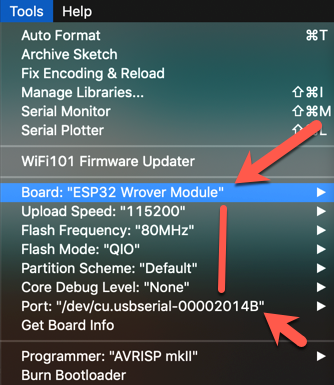
Now, you can set the ESP32 board target and its port, as shown in the following screenshot:
Now, you can compile and upload the Sketch program via Arduino software. If you succeed, you can see the program output as shown in the following screenshot:
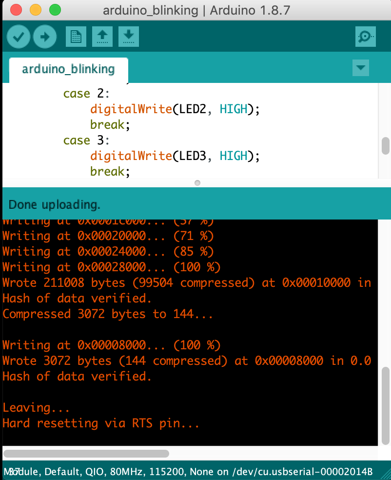
If you still get errors, please verify your ESP32 board type and its serial port.