Book Image

Blender 3D Printing by Example

By : Vicky Somma
5 (1)
Book Image

Blender 3D Printing by Example

5 (1)
By: Vicky Somma

Overview of this book

Blender is an open-source modeling and animation program popular in the 3D printing community. 3D printing brings along different considerations than animation and virtual reality. This book walks you through four projects to learn using Blender for 3D Printing, giving you information that you need to know to create high-quality 3D printed objects. The book starts with two jewelry projects-- a pendant of a silhouette and a bracelet with custom text. We then explore architectural modeling as you learn to makes a figurine from photos of a home. The final project, a human hand, illustrates how Blender can be used for organic models and how colors can be added to the design. You will learn modeling for 3D printing with the help of these projects. Whether you plan to print at-home or use a service bureau, you’ll start by understanding design requirements. The book begins with simple projects to get you started with 3D modeling basics and the tools available in Blender. As the book progresses, you’ll get exposed to more robust mesh modeling techniques, modifiers, and Blender shortcuts. By the time you reach your final project, you’ll be ready for organic modeling and learning how to add colors. In the final section, you’ll learn how to check for and correct common modeling issues to ensure the 3D printer can make your idea a reality!
Table of Contents (16 chapters)

Thinking about printing processes

Not all 3D printers work in the same manner. The printers at the Service Bureaus, such as Shapeways, Sculpteo, and iMaterialise, use different types of technology than what is typically seen with at-home desktop printers.

All 3D printers will start with your 3D model and use an additional piece of software called a slicer to cut your object up into small cross sections, or layers. From there, all the printing processes will create your object one layer at a time. Different types of printing, however, add the material in different manners. Those differences in production processes can impact how you approach your design.

Home printing – Fused Filament Fabrication (FFF) printers

Currently, the most common printers you would find in a home, library, makerspace, or neighborhood 3D Hub are what are called the Fused Filament Fabrication (FFF) or Fused Deposition Modeling (FDM) printers. I often describe these printers as similar to the hot glue guns you would see used for crafting or electronics projects. A spool of plastic string (filament) is fed through a hot end that heats the plastic up to the point where it is malleable and the printer can draw with it. The printer will print one layer of your object directly on a platform called the built plate, move up, print the next layer, and so on until your piece is finished.

Overhangs

With the exception of the Made in Space printer on the International Space Station, FFF/FDM printers are subject to gravity. Higher portions of your model will need a foundation or support from the lower ones. As a design consideration, you'll want to be conscious of the slopes in your piece, the overhangs. The angle of those overhangs impact how far a layer extends over the previous layer one. If a layer extends out too far, the filament could droop or curl up, causing imperfections, or worse, a failed print.

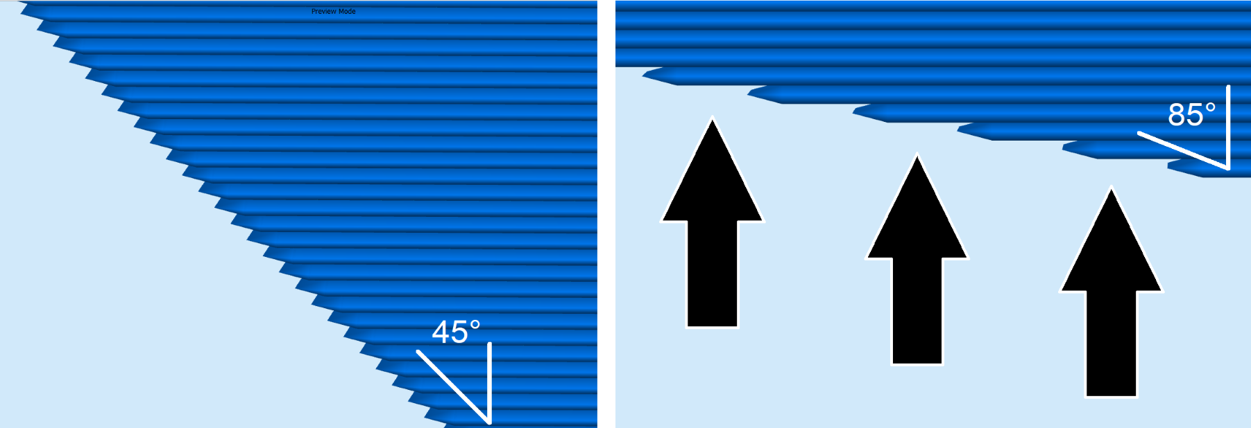
For most FFF/FDM desktop printers, the rule of thumb is 45 degree overhangs. If you keep your slopes and curves to 45 degrees or less, each layer will have a good foundation with the layer underneath. When you look at larger angles, you can see how layers may have trouble supporting their own weight. The following image shows the difference between 45 degrees and the more troublesome 85 degrees:

Layers at 45 degrees or less can be reliably printed by FFF/FDM printers. As the angle increases, it becomes harder for the plastic lines to support themselves.

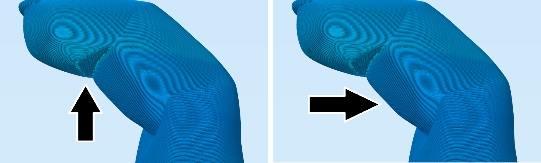
The human hand model later in the book is one where thinking about overhangs will be important. If one of the fingers was angled more than 45 degrees, you can see in the slicer preview how the printer would be drawing lines with nothing underneath it. For other portions of the finger that are more upright, you would see that each layer has good contact with the layer underneath:

Portions of the tip of the finger will be printing over air with nothing underneath. Earlier sections of the finger are better angled for printing.
Find out your printer's capabilities
If you want to put your particular printer to the test and get an assessment of its overhang capabilities, try the Massive Overhang Test by thingster on Thingiverse at https://www.thingiverse.com/thing:40382.

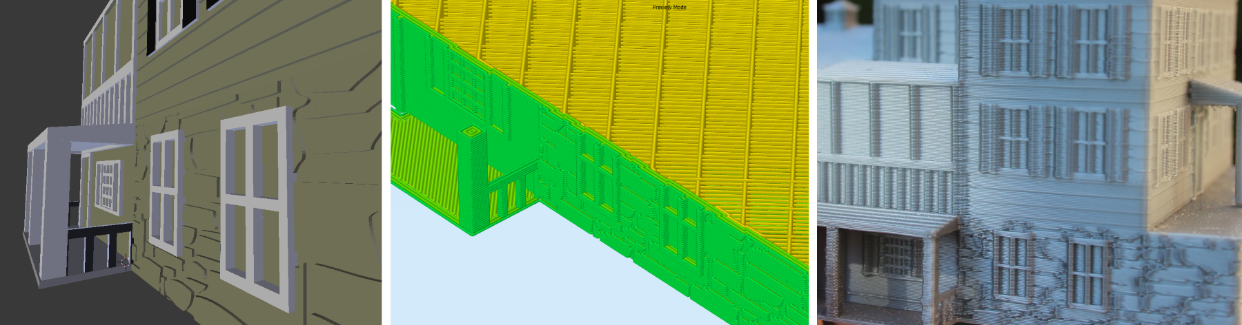
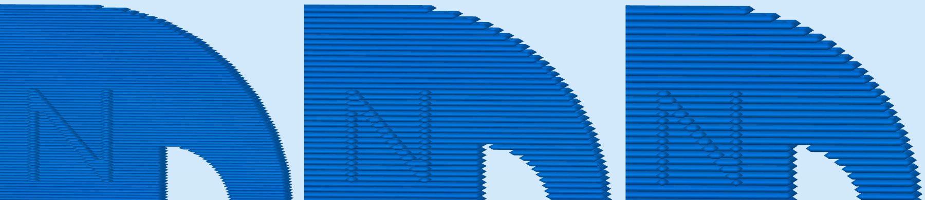
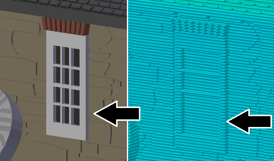
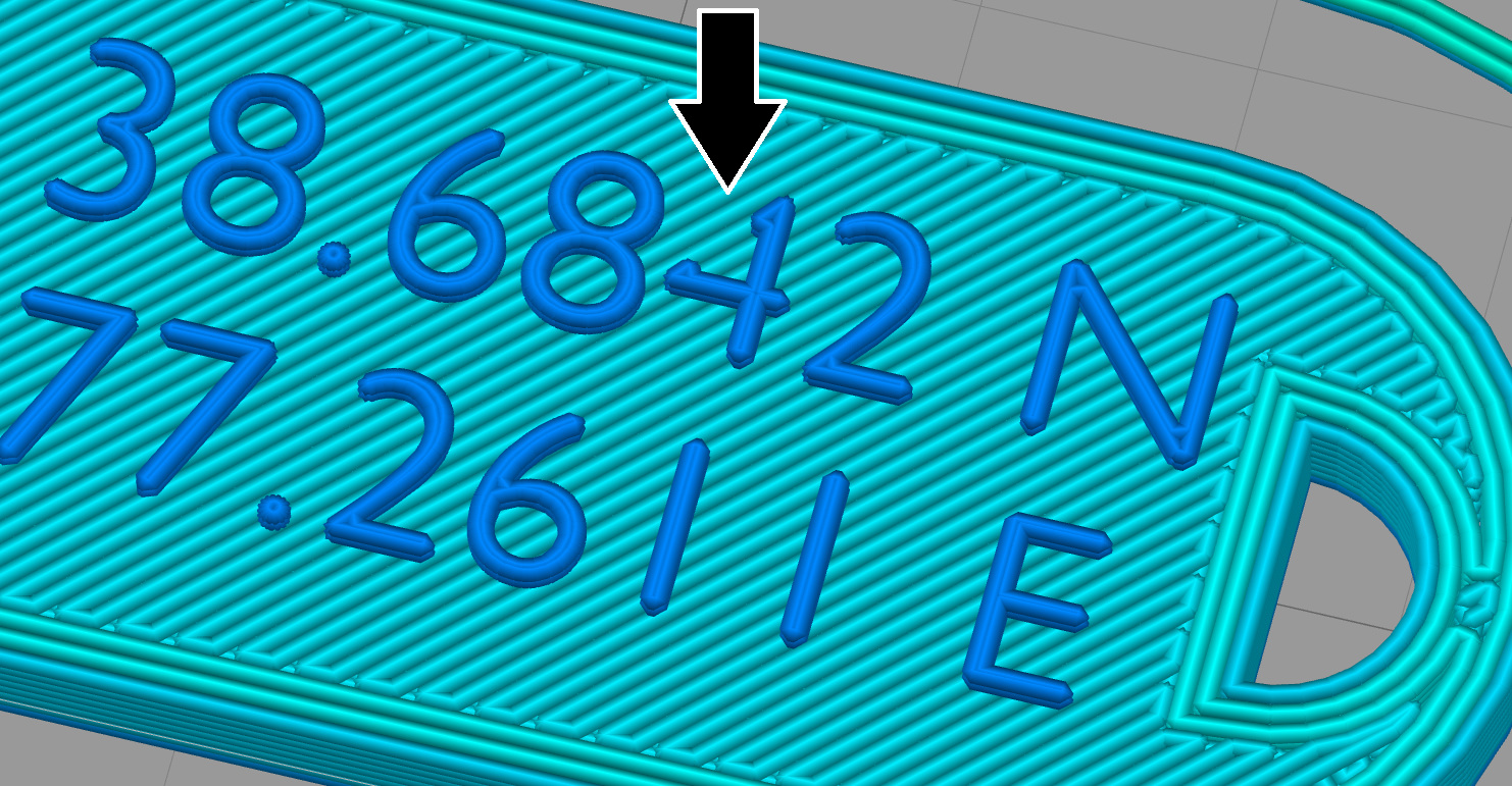
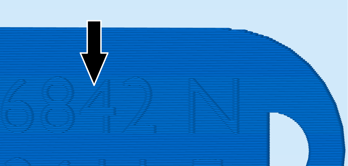
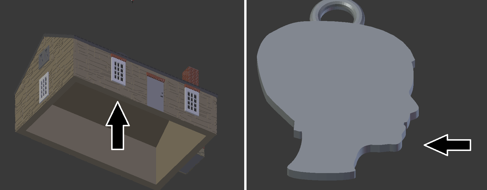
There is a lucky exception with overhangs. When the printer starts a layer, it usually starts by printing perimeters, sometimes called outlines, of your object before filling in the inside. The molten plastic likes to stick to itself. That is exactly why FFF/FDM printing works. If your printer draws its outlines from the inside of your object to the outside of your object, the last outline, the part of your object that is visible, sticks enough to the earlier outlines that it can support its own weight. That gives the printer the ability to do small, unsupported 90 degree (completely horizontal) overhangs, a handy behavior for detailing of your model, giving it texture or personalization:

You can put small, completely horizontal overhangs in your design. When the printer works inside out, outer lines can stick to previously printed lines for that same layer, permitting fine detailing for your model.

How far can those details come off a vertical face of the print? It will depend on the nozzle size of the printer. I have found 0.5mm to work great with both 0.35 and 0.4mm nozzles.

Find out your printer's capabilities
If you want to get an idea of what kind of unsupported details you can achieve on your printer, the Vertical Embossed Detailing - Remix by SpikeUK on Thingiverse is a good print to get an assessment: https://www.thingiverse.com/thing:2462735.

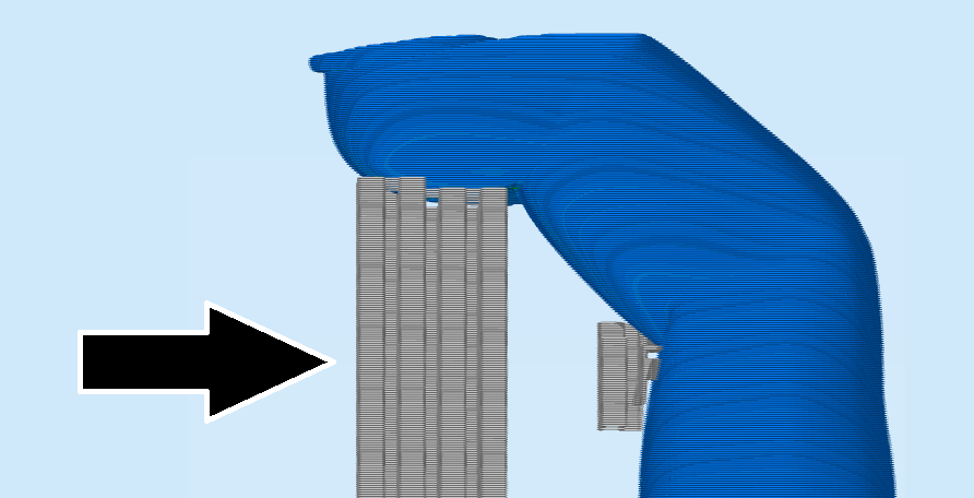
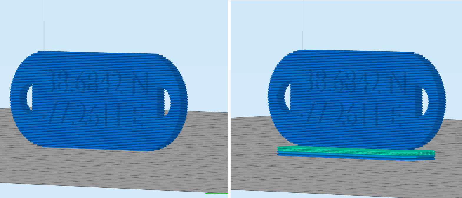
If you do have a design that requires large overhangs, you do not have to necessarily despair and abandon the idea. The slicer can tell the printer to print some extra columns called supports to assist your object. This is extra work for the printer that will add to your material usage and printing time. In addition, supports can leave markings on your piece, requiring sanding and cleanup to be done afterward. You don't have to avoid large overhangs when modeling, but it makes the printing process a lot cleaner if you do:

An example of temporary supports the printer can use to assist your object.

Detailing

If you were to crochet with thin embroidery floss, you could achieve a much more intricate level of detail than if you were working with thick yarn. The width of the thread being used plays a key role in what can be achieved in the final product. You can think of FFF/FDM printing as also using a thread, a small thread of plastic. With FFF/FDM printing, there are two dimensions of that thread that impact our detailing.

Layer height

When the slicer is cutting up your file into small cross-sections for 3D printing, the height of those cross sections is called the layer height. This can not only vary from printer to printer, but it can also vary from print to print. A smaller layer height would cut your model up into more cross sections. It would be a longer printing process, but at the same time would give your object a greater level of detail and resolution. In my prints, the layer heights tend to be between 0.10mm-0.25mm layers.

The following image shows the same piece with three different layer heights. As the layer height increases, the level of detail decreases:

As layer height increases, you will have faster printing times, but less detail.

Thinking ahead about layer height is a worthwhile venture when embarking on a 3D modeling project, particularly if you are planning small detailing. Consider the house figurine that will be highlighted later in the book. If the window panes are shorter than the planned layer height, the slicer (and therefore the printer) will skip that detailing, as shown in the following image:

In this example, a window pane is smaller than the layer height and is skipped by the slicer and printer.

Extrusion width

As your printer lays down lines of malleable plastic to bring your model to life, the hole in the nozzle impacts how wide those lines are. You can also think of it as your thread width, how wide the thread of plastic that comes out of your nozzle is. A more technical term is extrusion width, how wide the extruded plastic is. That width isn't necessarily equal to your nozzle size. For example, a nozzle with a 0.4mm hole may be using a 0.42mm extrusion width.

Find Your Extrusion Width

You may be able to look up your extrusion width in your slicing software. Different slicers use different terminology. Three examples are:
Slicer Setting
Simplify3D Extrusion Width
Cura Line Width
Slic3r Extrusion Width
If you aren't able to look up your specific extrusion width, start by designing for your printer's nozzle size instead.

Extrusion width is important to consider during design as it can also impact the detailing of your piece, which is most readily visible on the top. Later in the book, we will create a bracelet with custom coordinates on the top. If that piece was printed flat on the bed and portions of text were thinner than the extrusion width (such as part of the number 4 in the following image), that detail could very well get skipped:

A section of the number four in the coordinates is thinner than the extrusion width, so it is skipped by the slicer and printer.

Layer heights are smaller, sometimes substantially so, than extrusion widths. That means detailing going up vertically can be finer than the horizontal details you have at the top. If we printed that coordinate bracelet on its side, the same number we had trouble with before shows up fine:

Vertical details can be finer than horizontal ones.

Wall thickness

Wall thickness is simply how thick your printed object is from side to side. Wall thickness directly applies to the strength of that section of the piece. Technically, you could have walls as thin as your extrusion width. You could have your printer print a single line of plastic thread for your entire piece and there are many examples of beautiful vases printed in that manner.

Depending on your application, that may not be the best plan of attack. A thin wall of 0.42mm is easy to break. Our first model in this book is a pendant based on the profile of one of my sons. This is a sentimental piece. Surely, I would not want the clasp to break during my daily activities. I would want to give the hook for the pendant enough strength to survive the wear and tear of my daily life. On the other hand, railing detailing on a house figurine would be purely decorative and not be subject to the same stress. I could go smaller there.

Another thing to consider is how this section of your print is attached to the rest of the model. If it is a wall connected to other sections on two or more sides, it is considered a supported wall. It does not have to have to be as thick as a wall that stands by itself, an unsupported wall. The front wall of a house figurine is an example of a supported wall. It is attached to many other sides, the left side of the house, the right side of the house, the roofing. On the other hand, the thickness of a profile pendant, I would consider an unsupported wall:

The front wall of a house is a supported wall. The thickness of a profile pendant is an unsupported wall.

It is not a hard and fast rule, and you may fine-tune what works best with your printer. As a starting point for your design requirements, I tend to give supported walls at least 1mm in thickness and unsupported walls at least 2mm in thickness. For sections that I feel may need extra strength, I consider sizing those portions up to 3-5mm.

Other considerations – flat bases

With FFF/FDM printers, the printer starts with one initial layer which, if all goes well, sticks to the print bed for the duration of the print. If you have seen musings about hairspray, glue sticks, painter's tape, those are all measures to assist that important first layer in staying put. When you are designing for an FFF/FDM printer, it is ideal for the design to have a good footprint, a perfectly flat section to print straight on the print bed.

Sometimes a nice flat base isn’t going to be possible with the design you have in mind. The slicing software for the printer can assist in those cases. For designs that have small footprints that would not have a lot of contact area on the print bed, the slicer can add a temporary foundation printed underneath your object, a raft, to keep that all-important first layer stationary. If we did decide to print the coordinate bracelet on its side to take advantage of better detailing, the base of that print is just a very thin line, not likely to stay secure for the duration of the print. The raft, however, helps give it a sturdy anchor:

The print on the left has little contact with the bed and would be prone to unsticking. A raft assists the print on the right.

Home printing – Stereolithography (SLA) printers

Another printing technology that is becoming more accessible at home is the Stereolithography (SLA) printer, commonly referred to as Resin Printers. Instead of a spool of plastic filament, the raw material for resin printers is a pool of UV-sensitive liquid. The printer works by using a UV light to cure and solidify just the sections that will become your object. Your object is raised slightly out of the liquid pool, a process called peeling, and then the printer will solidify the next layer of your object and so on.

Overhangs

SLA printers tend to have a lot more flexibility with overhangs. The design guidelines for one of the most common desktop SLA printers, the Formlabs Form 2, support up to 71 degree overhangs, a substantial improvement over the FFF/FDM printers. SLA printers can also handle those small, completely horizontal overhangs for embossed detailing. The Form 2 Design Requirements refers to those as unsupported overhangs and recommends keeping them at a height of 1mm or less.

Detailing

The Formlabs Form 2 can work in layer heights as small as 0.025mm. Its equivalence to extrusion width or nozzle size would be the beam of light that is interacting with the liquid resin. In the case of the Form 2, that is 0.14mm. Combined, the Form 2 Design Requirements say the printer can support details as small as 0.1mm.

Wall thickness

Although the light beam is 0.14mm, the Form 2 Design Requirements do recommend a minimum supported wall thickness of 0.4mm and unsupported wall thickness of 0.6mm. Part of the recommendation is due to the peeling process. Smaller walls could warp as your print is pulled out of the pool of resin between layers.

Other considerations – drain holes

If you are hoping for a design to be hollow inside, you will want to include holes in your model to allow excess, uncured, liquid to drain.

Service Bureaus – Selective Laser Sintering (SLS) and more

The 3D Printing Service Bureaus open up a lot of doors in regards to what materials you can have your pieces produced in. You can have your jewelry designs cast in precious metals such as gold and platinum. You can have functional items, such as bottle openers, printed in sturdy stainless steel. You can have your custom designed coffee cup made in food-safe porcelain.

When working with at-home FFF/FDM printers, sometimes you have to put in the investment to learn your printer and its capabilities. At the 3D Printing Service Bureaus, they have already done that assessment for you and have documented design requirements for each material:

Material requirements and design specifications from Shapeways, iMaterialise, and Sculpteo.

Overhangs

It can vary by material, but the printing processes at the large Service Bureaus often free you from the concern of overhangs. The industrial Selective Laser Sintering (SLS) printers used for Nylon pieces, for example, have an ingenious way to get around the gravity problem. The whole print bed is covered in a layer of nylon powder. A laser will heat up and solidify just the sections of powder that will become the first layer of your object. A fresh layer of powder is laid down on the printer and the laser will solidify the next layer of your object. The printing process finishes with a big block of powder on the printer. Your piece is dug out of the loose powder, much like an archaeologist excavating pottery from soil.

Because the excess powder provides a natural support system, even completely horizontal overhangs are achievable. You also don't have to worry about flat bases and having solid contact with the print bed. The extra powder from previous layers is there to act as a foundation no matter where or how small your object starts.

Details

Depending on the material and the process, the cutting edge printers at the 3D Printing Service Bureaus can offer up a higher level of detailing and resolution than your typical home printer. This will be specific to the material you select. High Definition Acrylate would permit embossed and engraved details as small as 0.1mm. Porcelain, on the other hand, has very different requirements. Porcelain pieces finish up with a glazing process. Since the glaze adds its own thickness to the piece, it could pool into crevasses and obscure shallow details. As a result, a model geared for porcelain would need to have much deeper engravings, at least 1mm.

Find the requirements of your material

The section name could vary in the Design Requirements or Material Information Sheets. Examples from three 3D Printing Service Bureaus are shown as follows:
Service Bureau Section(s)
iMaterialise Minimum Details
Sculpteo Minimum width and height details
Shapeways Minimum Embossed Detail, Minimum Engraved Detail

Wall thickness

The 3D Printing Service Bureaus offer a lot of perks with top-notch quality. Their services are, as expected, more expensive than a print from a desktop FFF/FDM printer. Part of the cost is determined by the amount of material you use. This could be expensive, particularly in the case of pricey cast metals such as platinum or gold. As you design for one of the Service Bureaus, you'll likely want to minimize the amount of material being used to keep your cost low. Suddenly the minimum wall thickness takes on a deeper meaning. To save cost, you may opt to make your object hollow. You may also opt to make your walls as thin as possible.

Find the requirements of your material
How thin can your piece be? Look for sections mentioning "wall thickness." Examples for three 3D Printing Service Bureaus are shown as follows:
Service Bureau Section(s)
iMaterialise Minimum Wall Thickness
Sculpteo Minimum wall thickness (flexible), Minimum wall thickness (rigid)
Shapeways Min supported wall thickness, Min unsupported wall thickness

Other considerations – escape holes

Since the SLS printing process creates a big block of powder, you will want to keep in mind how that powder will be cleaned out of your piece. If you intend for your piece to be hollow inside, for example, you will need to include an escape hole in your piece to allow the technicians to remove excess powder.

Comparing the Requirements

Although there additional printing processes, such as Binder Jetting, we don't have to discuss them all to understand how the process and the material can impact your design. Your decisions about overhangs, detail size, and wall thicknesses all vary with the final material and process. To serve as some starting guidelines, a summary of the three processes we did discuss are:

Design requirement FFF/FDM
(0.4mm Nozzle)
SLA
(Form2 at 0.10 Layers)
SLS
(Shapeways Strong & Flexible Plastic)
Minimum supported wall thickness 1mm 0.4mm 0.7mm
Unsupported wall thickness 2mm 0.6mm 0.7mm
Overhangs 45 degrees or less 71 degrees or less Any
Height of unsupported overhangs 0.5mm 1mm Any
Minimum detail (vertical faces) Layer height 0.1mm 0.2mm
Minimum detail (horizontal faces) Extrusion width 0.1mm 0.2mm
Other Flat base recommended Drain holes may be needed Escape holes may be needed

Even when you decide on how you'll print your design, there are still some questions worth reflecting on. For example, how big do you want your print to be?