

Practical exercise – creating a mini weather station
For our first project of this book, we will be creating a mini weather station that will be based on getting readings from the BME680 air quality sensor, which takes pressure, humidity, and temperature readings. We will be using the ESP32 as the microcontroller and a breadboard to connect the circuits.
The following section contains the instructions for this practical exercise.
Hardware
In this book, we use Arduino IDE as our IDE, as it is one of the most popular options for makers and has a large community support. Arduino is an open source piece of software that offers a wide variety of libraries for different types of sensors, devices, and IoT platforms.
For the microcontroller used in our experiments, we use the ESP32 from Espressif. The ESP32 is a powerful microcontroller that comes with integrated Wi-Fi and Bluetooth connectivity and has a strong support base within the IoT community. The board type we use is the NodeMCU ESP32S, which can easily be found on Amazon. There are many different ESP32 boards available, but please note that the pin position can vary between boards, so pay attention to this when using different boards.
It is important that we familiarize ourselves with the layout of the NodeMCU ESP32S. In Figure 1.11, we provide a pin layout diagram of the NodeMCU ESP32S. You can use this alongside your own direct observations to complete this exercise and gain a better understanding of how the pins interact with the other components that will be used in this chapter and throughout the book.
Do not worry if it looks complicated at first; you’ll get used to it with the practicals that you will undertake along the way!
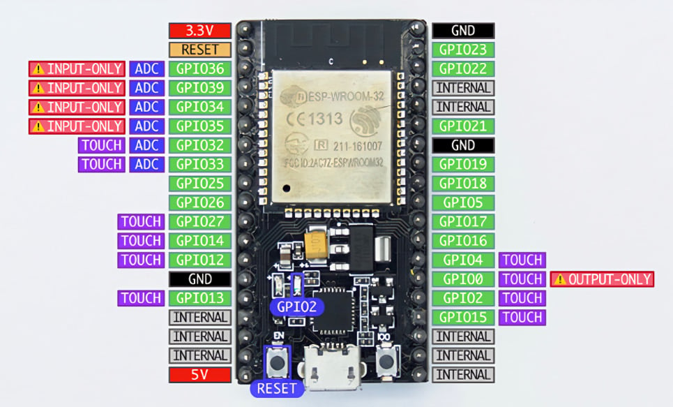
Figure 1.11 – NodeMCU ESP32S pinout diagram
We can now move forward and read from a sensor. The first sensor we will be working with is the BME680 sensor from Bosch Sensortech. This sensor can be easily found on Amazon, and it can measure relative humidity, barometric pressure, ambient temperature, and gas or volatile organic compounds (VOCs). You can find detailed information about this sensor at https://www.bosch-sensortec.com/products/environmental-sensors/gas-sensors/bme680/.
There are two ways to read the data produced by the sensor: through I2C or SPI. In this experiment, we will be communicating with the BME680 sensor through an I2C connection.
I2C, short for inter-integrated circuit, represents a connection method utilized in serial communication as a bus interface protocol. Commonly referred to as the Two-Wire Interface (TWI), it is a popular choice for short-range communication. This protocol relies on two bi-directional open-drain lines named SDA and SCL. The Serial Data (SDA) line facilitates data transmission, while the Serial Clock (SCL) line conveys the clock signal.
Since the I2C bus can be used to connect multiple devices, each device connected to the bus should have a different address to distinguish it from others.
We need to connect the SCL pin of the BME680 board to D22 on the ESP32 board (or IO22 on other ESP32 board), the SDA pin of BME680 to D21 on the ESP32, the VCC of BME680 to the 3V3 pin of the ESP32, and the GND pin on BME680 to the GND pin on ESP32. We can use the protoboard or direct jumper cable between those boards. The connection should look like that in the following figure:
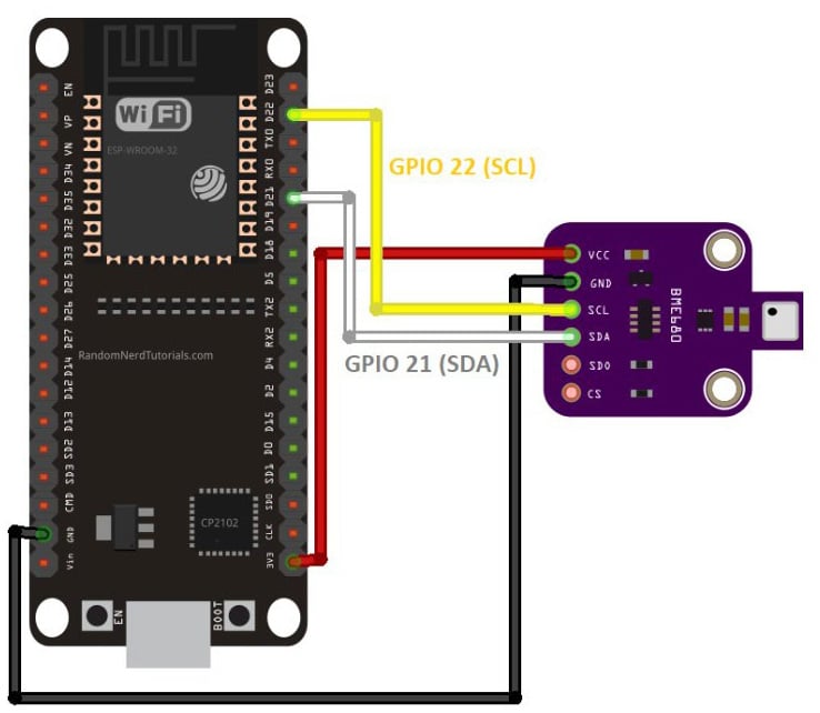
Figure 1.12 – Pinout diagram for attaching BME680 to ESP32
Working with the BME680
Due to the different addresses used by different BME680 board manufacturers, we need to verify the I2C address of the BME680 board we use (we also need to do this for every I2C device unless we already have the address from the manufacturer). To get the I2C address of the BME680 board, we need to use an I2C Scanner library:
- In Arduino IDE, we can easily find code for our requirements by using the Library Manager. To access it, click on Sketch | Include Library | Manage Libraries.
- Next, type
I2C scannerin the search bar. Several I2C scanner libraries will appear. The one we will be using is from Luis Llamas, but you can try other libraries as well. To install the library, click on the Install button. - Once the library is installed, go to Arduino, click on File, then Example. Scroll through the examples until you find I2C Scanner under Examples from Custom Libraries. Point to I2C Scanner and click on Scanner to open the example code. The Scanner sketch will appear in the Arduino window, and you can upload the code to your ESP32 board by clicking the
 button.
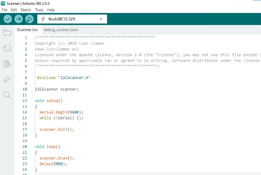
Figure 1.13 – Expected display for the IC2 Library in Arduino IDE
After finishing the upload, click on Tools | Serial Monitor to see the Arduino console (the older version will open a new window while the newer version will split the Serial Monitor under the Sketch window). You need to adjust the Serial Monitor baud rate to match the baud rate set in the program by finding the command in the void setup() function:
Serial.begin(9600);
This code sets the serial communication baud rate of the ESP32 board to 9600 baud, so we need to set the Arduino Serial Monitor window baud rate to 9600 to match the board. After this, we need to reset the ESP32 board by pressing the Reset button (marked EN) on the board.
If everything is set up properly, you will see the result in the Arduino window like in Figure 1.14:
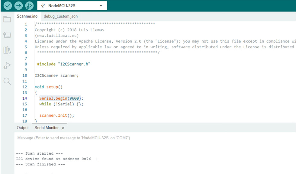
Figure 1.14 – Expected display for serial communication setup in Arduino IDE
Now we know that the BME680 board is using I2C address 0x76H.
- Click on Sketch | Include Library | Manage Libraries and search for
bme680. ChooseBSEC Software Libraryby Bosch Sensortec. Click on the Install button. After installing, click on File | Examples, scroll down through the examples until you findBSEC Software Library, and click on the basic sketch. It will open the sketch. You can find this sketch also in thei2csample.cfile in thePracticalfolder within theChapter01folder in the GitHub repository.Verify the sketch by clicking on the
 button, and if there’s no error, upload it to ESP32 by clicking the button.
 - Open the Serial Monitor, set the baud rate to
115200to match the sketch setting, and reset the board by pressing the EN button.
ESP32 Wi-Fi auto-configuration
The ESP32 has a built-in Wi-Fi functionality and can be set as an access point or a station. If it is set as an access point, you can connect your devices (mobile, other Wi-Fi devices, or computer) to it. If it is set as a station, you need to connect the ESP32 to an access point before you can read its data or it can send data to a remote server over the wireless network or internet (if the connected access point is connected to the internet). The ESP32 can also be set up as both an access point and station concurrently. This function is normally used to enable connecting the ESP32 to the available access point without having to manually configure the Wi-Fi setup and download it through a USB connection to the ESP32, which is difficult for common users.
There are two common methods of connecting the ESP32 to the Wi-Fi access point: manual and auto-configuration.
Manual configuration
The basic configuration of setting up an ESP32 connection to the access point involves manually entering the Wi-Fi SSID and password to the Arduino sketch and uploading it to the server using a serial USB cable. This manual Wi-Fi setup is very difficult to implement in real-life applications since many device users cannot do programming and Arduino IDE setup. Due to that issue, there is another way of setting up the Wi-Fi SSID and password—auto-connect configuration—which we will outline and use.
Auto-connect configuration
Another way to connect the ESP32 to the access point without having to hardcode the Wi-Fi SSID and password in the sketch and upload it to the ESP32 using a USB cable is by using auto-connect configuration. In this way, the ESP32 will be in the access point first, and if we connect to it using other devices (mobile phone or computer), it will display menus to guide us to connect to an available access point it can find by providing Wi-Fi credentials (i.e. SSID and password). Once we confirm, it will store the credentials in its memory, and then it will restart in Wi-Fi station mode and use the stored credentials to connect to the targeted access point. When we reset the ESP32, it will still be in station mode and will keep trying to connect to the designated access point.
One of the Arduino libraries that support auto-connect configuration is ESPAsync_WiFiManager, built by Khoi Hoang. The benefit of using asynchronous Transmission Control Protocol/User Datagram Protocol (TCP/UDP) connection is that the processor does not have to wait for each connection to finish before it can serve other requests, so multiple connections can occur concurrently. This will also enable faster responses.
ESPAsync_WiFiManager installation
Next, we will need to set up the ESPAsync_WifiManager library to configure the Wi-Fi connection for the ESP32 and proceed with our next steps:
- Search from
Manage Librariesto findESPAsync_WiFiManagerand install it. We also need to download the dependency libraryESPAsyncDNSServer, which, unfortunately, cannot be found via theManage Librariessearch. For libraries that cannot be found in the Library Manager search results, we can download them by searching for them on the internet and downloading the library as a.zipfile. We can download theESPAsyncDNSServerlibrary at https://github.com/devyte/ESPAsyncDNSServer and save the code as a.zipfile. - To install the
.zipfile library we just downloaded, click on Sketch | Include Library | Add Zip Library and select that file. - In a new Arduino sketch screen, click on File | Examples |
ESPAsync_WiFiManagerand open theAsync_AutoConnectsketch. Verify the sketch by clicking on the button, and if there are no errors, upload it to ESP32 by clicking the button. Reset the ESP32 board by pressing the Reset (marked EN) button.
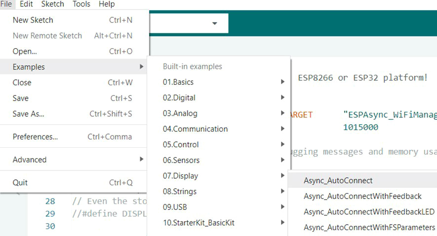
Figure 1.15 – Opening the Async_AutoConnect sketch on Arduino IDE
- From a mobile phone or computer, search for a Wi-Fi access point to find
ESP_******_AutoConnectAP, where******is the six digits of the hex number related to the ID of the ESP32. Connect to this access point with a password in the formatMyESP_******, where the******should be the same six-digit hex number as the ESP32 ID. After connecting to the ESP32 access point, a browser window will open. Follow the guidance from the menu to enter the targeted access point SSID that the ESP32 should connect to and enter the password for the Wi-Fi connection. Once set, and once the ESP32 connects to that access point, the ESP32 will reset, change the mode to station mode, and automatically connect to the access point.
With this, we have successfully prepared the ESP32 to be able to communicate over Wi-Fi. We can now move on to setting up programming over the air (OTA) to be able to create and publish our code directly to the ESP-32 instead of having to connect it to our laptop.
ESP32 programming OTA with a web server and mDNS
Programming OTA allows updates to the code or configurations to be pushed over Wi-Fi so that we do not have to continually connect the ESP32 to the Wi-Fi when we push out updates to it. We will explore how we can set up the ESP32 for this so that the process of pushing out updates can go much more smoothly.
Copy the sketch on the repo named programmingOTA.c in the Practical folder within the Chapter01 folder in the GitHub repository to the Arduino sketch window and save it as ESP32_ElegantOTA_mDNS.
Verify the code using the ![]() button and upload to ESP32 using the
button and upload to ESP32 using the ![]() button. Press the Reset (EN) You should get a welcome message in your browser.
button. Press the Reset (EN) You should get a welcome message in your browser.
ESP32 reading the BME680 sensor
Now, we can begin configuring the parameters that we want to have measured from the environment. To do this, we need to code up the necessary code for the sensors so that they can connect to the ESP32 and read in accordingly.
As part of this, we can configure the libraries and the code for the BME680 sensor, which allows us to measure gas, pressure, temperature, and humidity:
- You need to install additional libraries:
- The Adafruit
BME680library together with its dependencies, i.e.,Adafruit UnifiedSensor Library. - The
ESPAsyncWebServerlibrary from https://github.com/me-no-dev/ESPAsyncWebServer/archive/master.zip. Install this library by navigating to Sketch | Include Library | Add .ZIP Library and choose the downloaded file. - The
AsyncEleganOTAlibrary from https://github.com/ayushsharma82/AsyncElegantOTA. Install this library using the method in step B. - The
ESPmDNSlibrary from https://github.com/espressif/arduino-esp32. Install this library using the method in step B. - The
ESPAsynclibrary from https://github.com/me-no-dev/ESPAsyncTCP/archive/master.zip. Install this library using the method in step B.
- The Adafruit
- Copy the sketch in the
ESP32_BME680_OTA_mDNS.cfile in thePracticalfolder within theChapter01folder in the GitHub repository to a new Arduino sketch and save it asESP32_BME680_OTA_mDNS. Please do not forget to change the Wi-Fi SSID and password according to your Wi-Fi access point setup. - Verify the sketch by clicking on the button, and if there are no errors, upload it to ESP32 by clicking the button. Open the Serial Monitor and set the baud rate to 115200 to match the sketch setting and reset the board by pressing the EN button. Your Serial Monitor window should look like this:
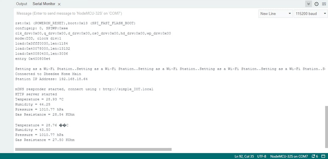
Figure 1.16 – Expected output from the Arduino IDE Serial Monitor
- As the code also creates a web server, you can see it being visualized by opening your web browser and typing the address
http://simple_IOT.local.
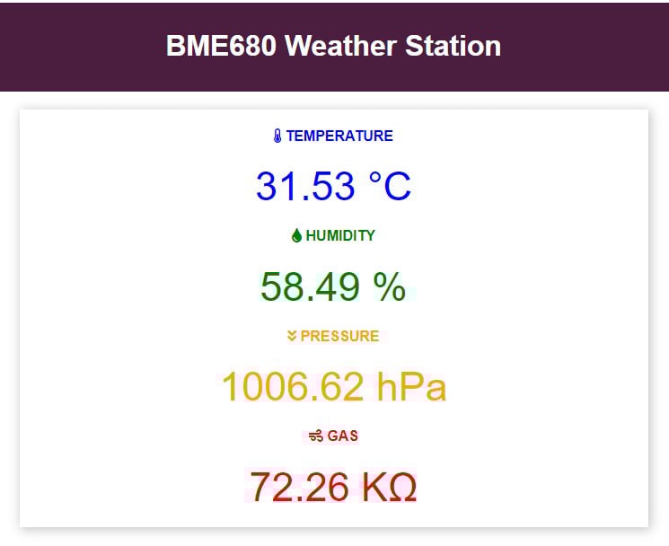
Figure 1.17 – Display on the local web server
And that’s it; you’ve made your first IoT-based project! Now upload the code to GitHub and see whether you can also make these modifications to your hardware/code to further understand and practice the concepts that you have learned through this practical exercise:
- Can you switch the BME680 sensor with a soil humidity sensor in your kit? Which modifications do you need to make to your circuit and software for that?
- Can you modify the sample rate of the data so that it samples two times in one second?
Feel free to use the documentation from the Keyestudio Super Starter Kit to help you navigate the use cases of each sensor and how to properly use them. Throughout this book, the internet is going to be an effective helper for you; particularly as there may be some concepts that you may not know. However, we always intend to explain each one as thoroughly as possible so that you do not need to do so.
Important note
When making changes to your code such as with these experimental problems, always make sure to commit your progress so that you can revert to previous versions when your current code does not work. This is important to remember, as you will certainly run into some dead ends in a project such as this and will need to backtrack to a working version to keep things on pace.
In this practical, you have learned how to create a mini weather station that can measure three different parameters. This will serve as a building block toward understanding the potential of IoT and for us to build on the concepts that have been learned here further in other practical exercises.