

Diving deep into Follow Me
Another command that people only scratch the surface of when they learn SketchUp is Follow Me. Generally, we see how Follow Me can be used to put crown molding in a room or can be used with a circle to make a bottle or pawn chess piece. Follow Me is made to extrude faces along paths, so these sorts of things are a perfect use of the tool.
Seems simple enough, right? There are, however, a handful of tips that will move Follow Me from a command you use in a few specific instances to a tool that you will keep on hand for daily use! In this section, you will see how Follow Me can become your go-to tool for creating fillets, rounding over corners, or even generating geometry quicker than any other SketchUp tool.
Follow Me and groups
The first thing to think about with Follow Me is how you set up your initial geometry. Something that many people don’t think about is using a group to separate the Follow Me geometry from base geometry or preselecting paths. Let’s create an example:
- Draw a large rectangle on the ground.
- Push/Pull the rectangle up so you create a box.
- Now use the Line and Arc tools to create a quarter circle in the middle of one of the sides of the top of the rectangle, as shown in this figure:
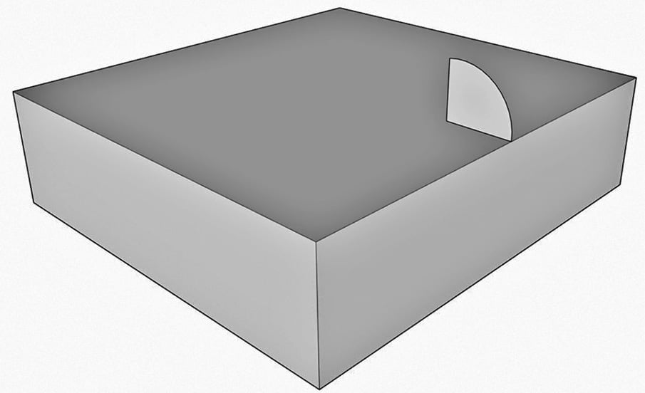
Figure 1.13 – Ready for Follow Me
- Select the Follow Me tool.
- Select the face you created with the Line and Arc tool.
- Move your mouse along the top edge of the rectangle.
Now, unless you are very steady-handed, there is a chance that your cursor may wander just a bit off the line as you move it around the model. When you do this, the profile you are pulling may jump all over the place, creating a crazy extrusion. Sometimes, it will jump down a side of the rectangle; other times, the profile will disappear completely.
Many first-time, self-taught users think that this is the way to use this tool, but there is a better way. The key to a quick and easy Follow Me is to preselect your path!
- Use Select with the Shift modifier key to select the top edge of the rectangle.
- Choose the Follow Me tool.
- Select the same face as last time.
Boom! With that, we have a nice, curved arc that follows the top of the rectangle!
However, if you select any portion of the new geometry, you will see that it is connected to the rectangle. Now, in many instances, there may be nothing wrong with this, as you may want a rim or surface detail to merge with the part geometry. In the case of something such as a chair rail or baseboard, you may want to keep them separate so you can edit them easier in the future or use a different material for them. Let’s redo that Follow Me command with one change.
- Use the Undo command to undo Follow Me.
- Double-click on our arced face (double-clicking will select the face and all the edges that define it).
- Right-click on the face and choose Make Group from the context menu.
- Now, use Select to select the edges around the top of the rectangle. Your selection should look like this:
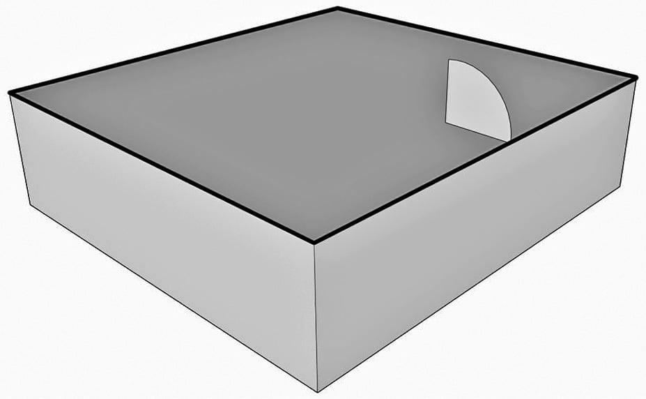
Figure 1.14 – Pre-selected Follow Me path
- Choose the Follow Me command.
The next step is to choose the face that should be used for Follow Me, but if you hover over the group that you created, you will notice that it is not a valid selection. At this point, we need to get inside the group temporarily to select the face.
- Right-click on the group and choose Edit Group from the context menu.
- Select the face.
- Use Select to click outside of the current group.
Notice that if you select the geometry that Follow Me created, it is in its own group. This means you can apply a different tag to this group than the base geometry or easily select all the geometry to apply a specific material. Having it in a separate group makes it much easier to work with!
One of the issues that many users run into with Follow Me is problems with the ends of the extrusion. Remember, when you create a face to be used in Follow Me, it should be perpendicular to the path. Let’s take a look at two examples, as follows:
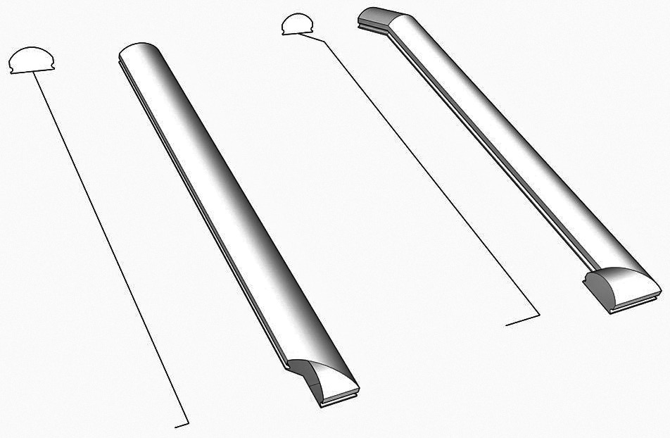
Figure 1.15 – These two examples show the face and path before and after Follow Me
In these examples, a simple profile was created for a handrail. In the example on the left, the profile is not perpendicular to the path and ends up squashed in the final extrusion. To make things worse, the end looks odd because the path is shorter than it should be.
In the example on the right, the path was extended out at both ends, and the profile was placed perpendicular to the end of the path. There may be cases like this where you may want to add geometry to the path or have your extrusion run long of where they will be in your final model. Remember, if you group the face, then the geometry will be easy to trim back after you have created a good-looking extrusion.
Let’s see another example of this with a half-torus. In this example, we will make two shapes and see how important it is to spend a little extra time on your path before using Follow Me. Start a new model and follow these steps:
- Draw a large circle on the ground with its center at the origin.
- Draw a line along the green access from one edge of the circle to the other, cutting the circle in half.
- Erase half of the circle and the line through the middle.
This gives you a perfect half-circle, right? In some cases, this would be a perfect half-circle, but for Follow Me, it might not be ideal. Let’s add another circle to this example and see what happens when we try to create a half-torus.
- Use the Circle command and the Left Arrow key to draw a circle at one end of the half-circle path.
- Put the circle in its own group.
- Run Follow Me with the half-circle as the path and the grouped circle as the face:
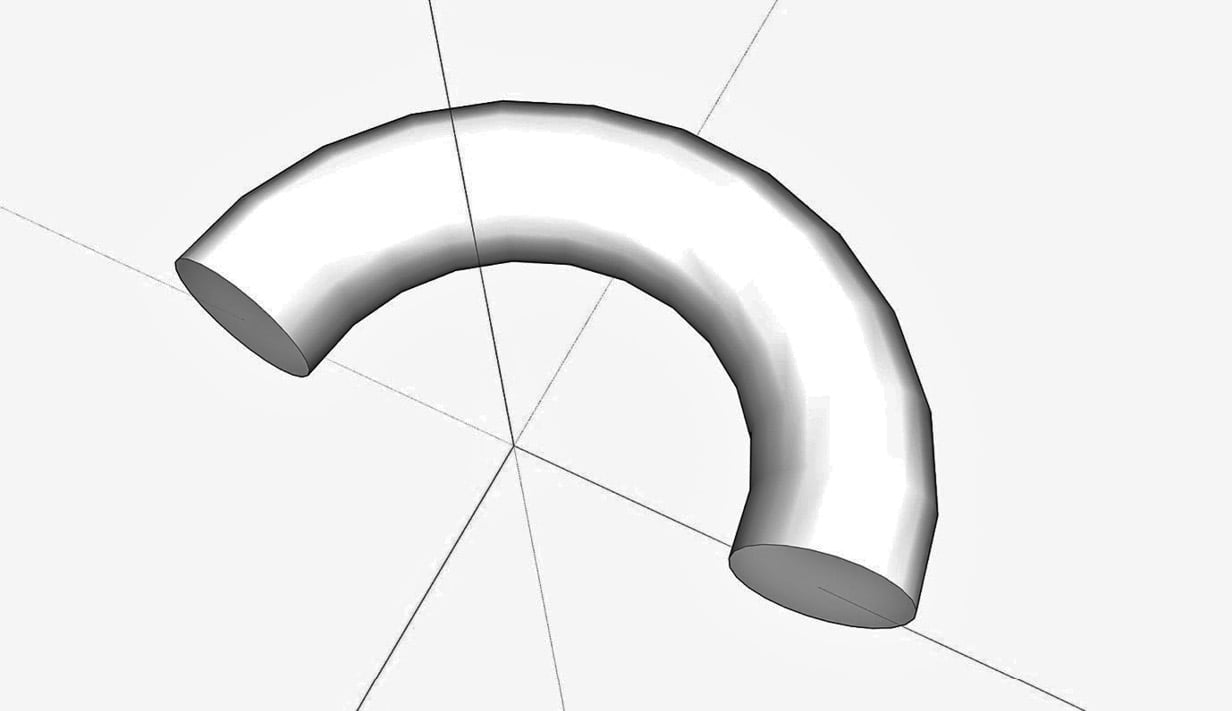
Figure 1.16 – This process did not create a perfect half-torus
Look at the geometry that has been created. Specifically, look at the ends. What is important to notice is how the faces of the extrusion are tilted out from the green axis. Also, while the shapes at the end may seem like perfect circles, check their dimensions using the Tape Measure. If you measure the end vertically and then horizontally you will find that they are not the same.
The issue with this Follow Me is that the shapes were not perpendicular to the ends of the paths, so Follow Me pushed the shape along the path at a little bit of an angle. Let’s try this again with one small change. Just so we don’t forget what this practice produced, group-select the whole thing and then move it off to the side.
Look at the circle. See how the axis hits the circle where two edges meet. What we want to do is rotate the circle just a little bit so that the green axis crosses the circle in the middle of an edge, rather than at an endpoint.
- Select the Rotate command.
- Use the origin as the center of rotation.
- Use the center of an edge as the start point for the rotation.
- Use the green axis as the second point.
- Draw a line across the circle like last time.
- Erase the bottom half of the circle and the line on the green axis.
Look at the edges of the circle you have created. The difference is subtle but important. We will see a big difference when we perform the same Follow Me steps with this geometry as a path.
- Use the Circle command and the Left Arrow key to draw a circle at one end of the half-circle path.
- Put the circle in its own group.
- Run Follow Me with the half-circle as the path and the grouped circle as the face:
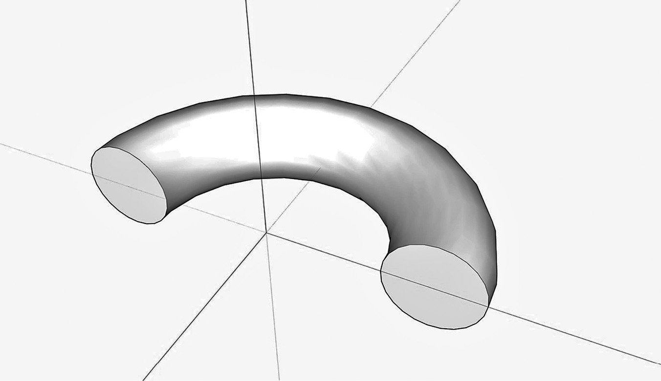
Figure 1.17 – The perfect half-torus
Look at this extrusion compared to the previous effort. The ends line up with the green axis and if you measure the ends, they are still perfect circles! Remember this example next time you use Follow Me and you will avoid issues with the extrusion coming up short or having weird end shapes!
Turning shapes with Follow Me
As mentioned before, Follow Me is often used to make shapes similar to a woodworker turning a piece of wood on a lathe. A profile is aligned with the center of a circle and Follow Me makes a shape based on the profile spinning around the circle. A few examples of this are shown here:
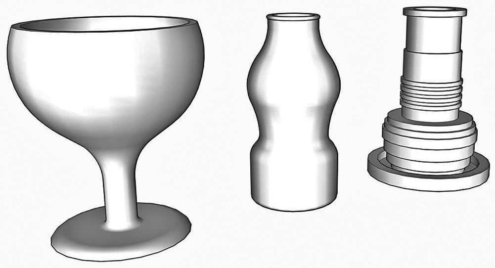
Image 1.18 – Turned shapes using Follow Me
Since the intention of this book is to introduce intermediate concepts and push you past the basic use of the SketchUp toolset, let’s consider a slightly different way to use this setup. Aligning a profile with the center of a shape to follow is a great concept and can be used to quickly create some great shapes, but people often don’t consider that the shape that is being followed does not have to be a circle. Let’s start a new file and model a fancy pedestal in just a few steps:
- Draw a square centered at the origin (use the Toggle Select Center modifier to start a rectangle on origin (Ctrl on Windows or Option on macOS) and watch for the dotted line to indicate square geometry).
While it is not strictly required that you do a Follow Me like this at the origin, it does make it easier on you. By centering the path geometry on the origin, you have a visual indicator of the center of the spin of the geometry.
The next step will be to create the profile. I find that the easiest way to do this is to create a working plane that I can draw my shapes onto. As long as one edge of the plane is along the origin, I know that Follow Me will create the properly turned geometry.
- Draw a rectangle on the red axis (Right Arrow) from the origin up from the square on the ground. You should end up with geometry similar to this figure:
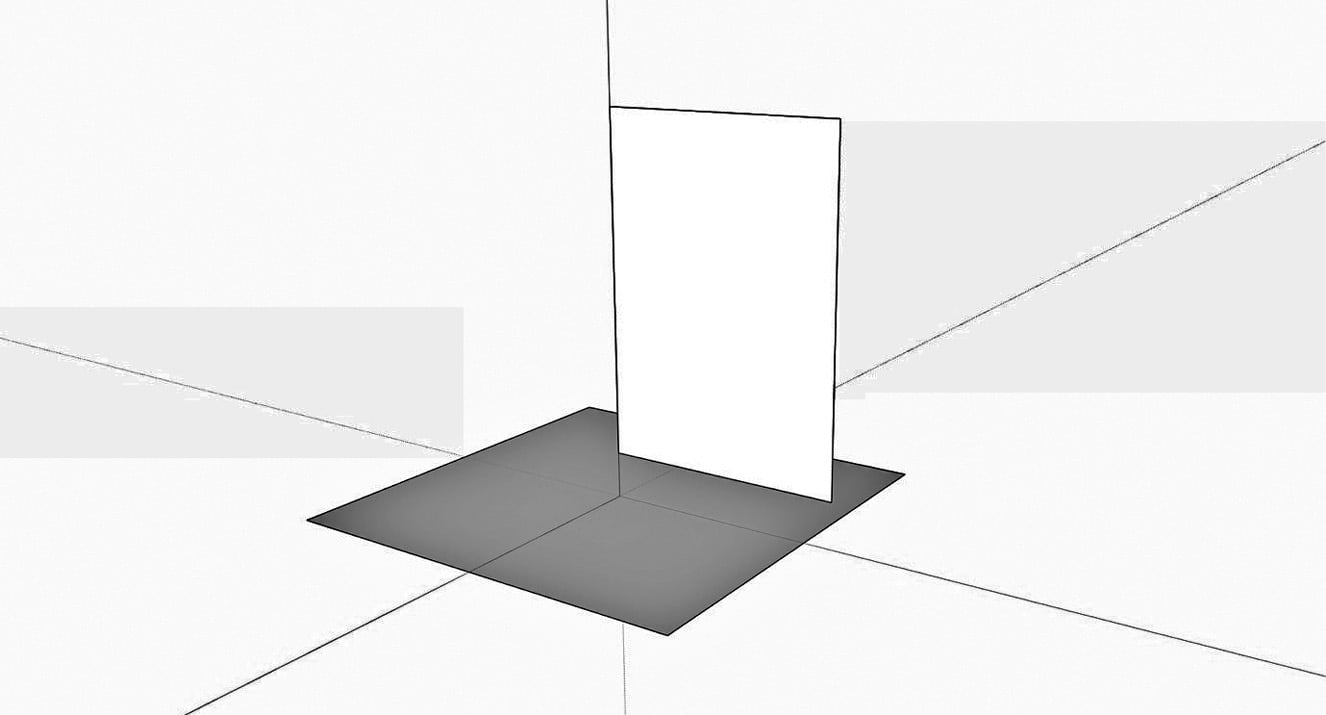
Figure 1.19 – Ready to start creating a profile
- The next step is to create the geometry of the profile. For this example, create something similar to what I have drawn here:
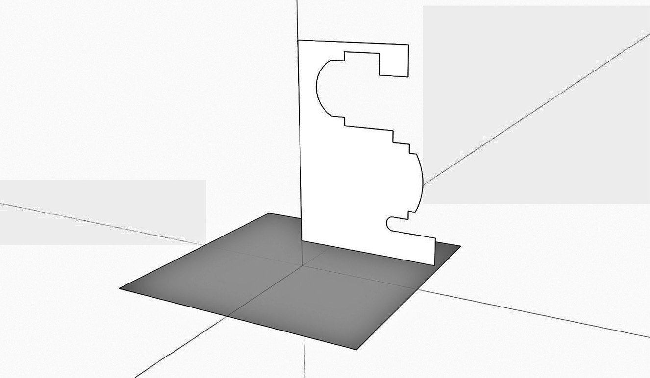
Figure 1.20 – Your profile may vary, but try to create something with a few corners and arcs
- Once you have the profile geometry drawn, erase the extra edges and double-click the profile, then right-click, and choose Make Group from the context menu.
- Select the square (you can choose the edges or simply double-click the face of the square to highlight all of the edges), choose Follow Me, then click the profile:
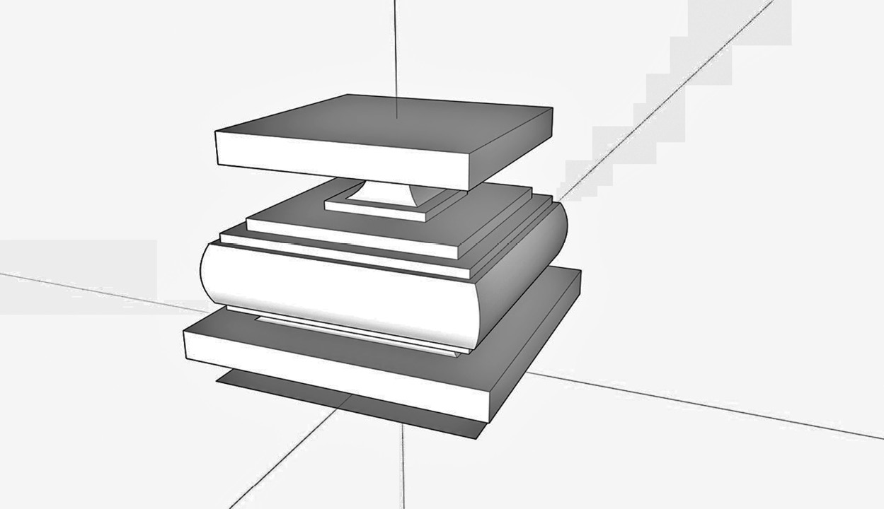
Figure 1.21 – Final geometry
That’s it! Your fancy pedestal is created. Any time you have geometry that follows along a shape, whether it is a linear extrusion similar to what we created in the first example, or if the geometry wraps around an enclosed shape like this pedestal, keep Follow Me in mind as you generate geometry!