
Anatomy of a CNC machine
Some of the basic components of a CNC machine were touched on in Chapter 1, The What and Why of CNC, but ahead of deciding which machine suits our purposes, we should know what the particulars are of each component. Here’s a view of a 3018 machine I built using some left-over frame parts from other projects and some 3D-printed components. The overall part count for the frame is very low, and most components can be obtained off the shelf. Most 3018 machines will look a lot like this:
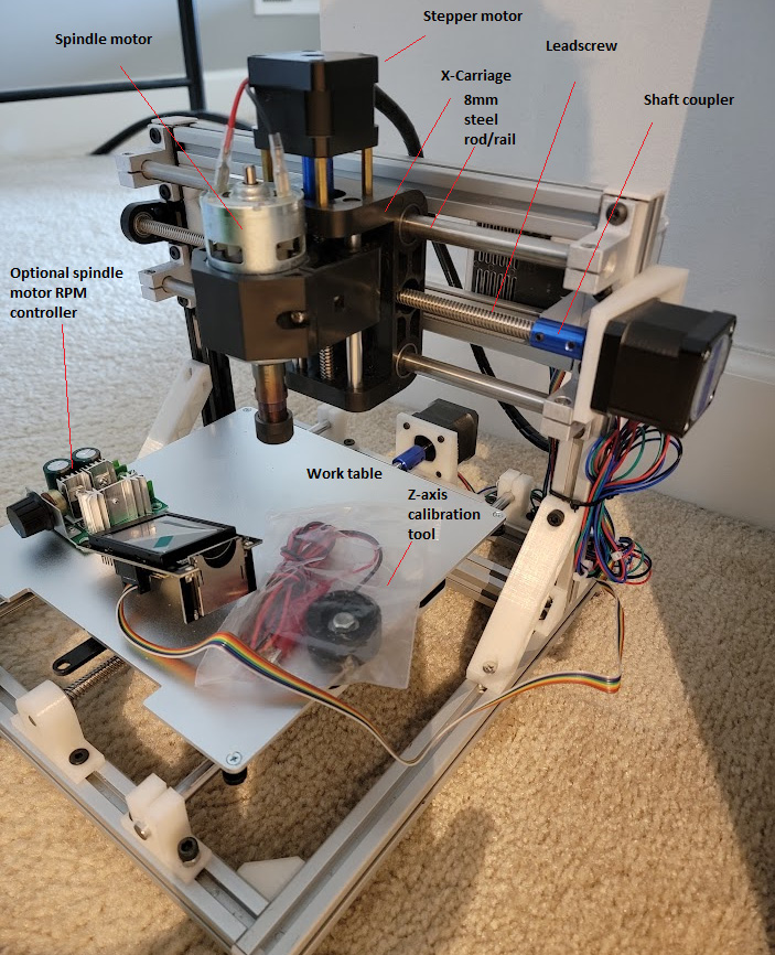
Figure 2.1 – 3018 front view
Looking at the labeled components in the preceding photo, we have the following:
- Spindle motor: We mentioned this component in Chapter 1, The What and Why of CNC. This is part of the toolhead and what drives the endmill bit. Think of it as nothing more than the motor out of a common hand drill with a chuck at the end of the drive shaft that will accept any of a variety of endmill bits. A review of commercially available machines may refer to this as a 775 Direct Current (DC) brushed motor. This is what many kits and pre-built machines come with. This particular motor came with a chuck already press-fit onto the motor’s drive shaft.
- Motor RPM controller: This optional item allows the user to externally control the revolutions per minute (RPM) of the spindle motor. Some older versions of GRBL can turn the spindle motor on/off and reverse its direction. After version 0.9, it became possible to use pulse-width modulation (PWM), a series of pulses turning the motor on and off and varying the duty cycle (how long the motor is running) to control the motor speed. In the absence of PWM, and when an upper limit for RPM is desired, the motor RPM controller comes in handy.
- Stepper motor: This motor is characterized by the ability to precisely control rotation, including holding the motor shaft stationary. These motors come in multiple designations (for example, NEMA 8, 14, 17, 23, and 34, which identify the size of the motor). Additionally, these motors have specific holding torque (the amount of force the shaft would need to experience to move it out of position) properties. Our 3018 machine uses three such motors, one for each axis (x, y, and z).
- Leadscrew: This is a helical precision screw that the stepper motor rotates to achieve motion in the x, y, or z axis. These also come in a variety of sizes (diameters and pitch), but for our purposes, we are using TR8 (8 mm diameter) leadscrews, which are very common. These have differing pitches (how much motion the leadscrew nut travels through each revolution of the leadscrew). For example, a 2 mm pitch means that the nut will move 2 mm with each rotation of the leadscrew. It should be clear that very precise movement can be made with these components.
- Shaft coupler: This connects the motor shaft to the leadscrew. Since the motor shaft is typically 5 mm in diameter and the TR8 is 8 mm, the coupler will have one end with a 5 mm bore and the other with an 8 mm bore. The coupler is secured to the leadscrew and motor shaft by tightening the screws on the side for a friction fit. A common problem with kit-built machines is having loose couplers, which interfere with the proper motion of the toolhead. Generally, couplers should be inspected after the build periodically to ensure they haven’t loosened.
- X-carriage: This carries the toolhead and the z-axis assembly. Unlike 3D printers, where the z axis is typically independent (CoreXY, D-Bot machines) or moves the x-axis gantry, many CNC machines carry the entire z-axis mechanism and move it left and right (in the x axis). This means this is a very heavy component, including the rails, z-axis frame, z-axis motor and leadscrew, and of course, the toolhead itself. z-axis travel is typically small and is represented by a negative number in G-code (where Z=0 is the surface of the material being machined).
- 8 mm steel rod: Not all CNC machines use these smooth, very durable rods for rails. However, many 3018 machines you will encounter use this as a standard for their motion systems. Other alternatives are linear rails, which are smoother, exhibit less wear over time, and are even more accurate (straight). They do, however, tend to be more expensive.
- Worktable: This is the surface on which you will place your materials to be machined. For my DIY machine, I used parts I already had in my parts bin, which included the metal platform from a long-defunct 3D printer. Many of the machines you will find online have extrusions in place of a worktable because those have slots that allow you to fasten clamps or even a wasteboard to the worktable (see Figure 1.1 in Chapter 1, The What and Why of CNC for another of my machines with an extrusion for a worktable). As the machine in Figure 2.1 was built explicitly for this chapter, we will later show some examples of how to secure workpieces of a wasteboard to the table.
- z-axis calibration tool: Because my machine is not using endstops (more on this later), we need to, at a minimum, determine where Z=0 every time we start a job (unless every piece of material we start off with is identical to the one before it). By setting Z=
0with this tool, we can be sure that our cuts (especially where we need to cut to specific depths, such as when drilling holes) are very accurate. This tool is not attached to a controller all the time, but rather is removed once the z axis is homed (that is, set to its lowest limit; in this case, Z=0).
A note on wasteboards
Wasteboards are consumables where CNC is concerned. Ideally, you would never need these because you will have precisely homed your z axis and your material to lie perfectly flat against the worktable, and your design ensures that your endmill will never touch the worktable. Of course, that implies a huge amount of trust in a machine, and no machine can be 100% trusted to perform exactly right all the time, every time. A wasteboard ensures that if there is an error, any damage is confined to it.
Now, let’s have a look at another view of the same machine. Figure 2.2 gives you a closer look at the same components we discussed up till now in this section, and we can see a few more:
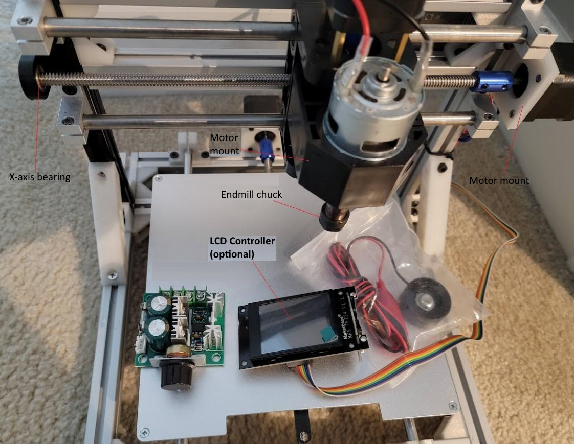
Figure 2.2 – 3018 top view
Notice how the screws are holding the worktable to the frame underneath (which was harvested from a dead 3D printer) and are countersunk into the worktable. This ensures that whatever is placed on top of the worktable lies flat and can consume all the real estate presented by it. Looking at this picture, you see the 775-motor mount. There are different-sized motors that dictate what you have: a mill or a machine. The same motor mount (if you look very, very closely, toward the front) has these small notches/grooves cut into the inside of the mount. These allow you to insert a laser toolhead (which is typically square-shaped) into the same mount whenever you want to switch from CNC to laser and back. On one of my other machines, I have fastened my laser head to the side of the motor mount so that I don’t have to keep swapping toolheads.
3D printer and printed parts for this machine
This machine makes extensive use of spare parts in my parts bin as well as 3D printed parts found on https://www.thingiverse.com. Most designs on this site are free to use for non-commercial purposes without prior permission. There are other sites where you can download models and designs for a fee (such as https://cults3d.com/en), but there is plenty to explore at Thingiverse and Thangs (https://thangs.com/). These two sites are where I usually go for part designs when I am building from scratch. Most if not all the parts I 3D printed can also be purchased at various online shopping sites such as Amazon. In my case, I purchased an X-carriage (which includes the z-axis assembly) because the 3D-printed equivalents proved to be unreliable for heavy-duty use on previous builds.
Looking at Figure 2.2, we can see the following components:
- LCD controller: This component is entirely optional, and allows for the operation of the CNC machine as a standalone unit. The computer is not needed to control the machine, only to generate the G-code, which can be copied onto an SD card and loaded into the controller.
- Motor mount: Stepper motors are secured here. In Figure 2.2, you see two of these for x and y, while the z-axis motor mount is largely made of brass standoffs. Because of the orientation of the motor, different forces act on the motor. In x and y, these are largely the same, but in z, you have more compression/tension loads owing to gravity and the need to pull and push a load with the leadscrew against or with gravity.
- Endmill chuck: This is just the part in which the bit is inserted. The bit is secured the same as you might in a hand drill. You hand tighten the nut at the bottom of the chuck, and that secures the bit in place (unlike a typical drill bit, however; endmill shanks are square to reduce the likelihood of the bit slipping in the chuck).
- x-axis bearing: On the 3018 there are two similar bearings. One of them is this one, for the x axis. While you could have a setup where this bearing does not exist, your x-axis leadscrew will wobble, which will lead to inaccuracies in movement. On desktop 3D printers, many manufacturers leave the z-axis leadscrews free on the non-motor end, and you would be well served to add a bearing there to prevent wobble. The other place you have a bearing such as this is on the y axis, which moves the worktable forward and backward.
Finally, let’s have a look at the rear of the CNC machine in Figure 2.3:
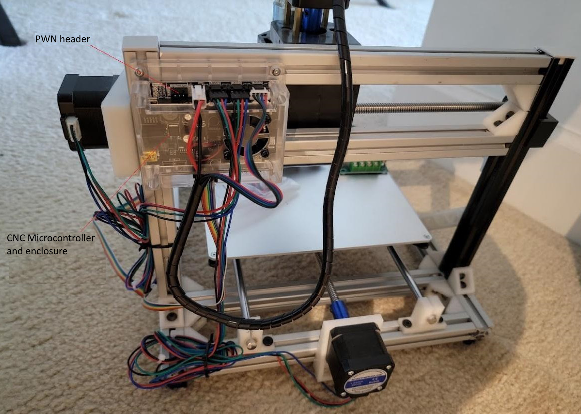
Figure 2.3 – 3018 rear view
In the preceding photo, you can again see the same familiar components as in Figure 2.2 and Figure 2.1. Notice the 8 mm rod mounts here. When I was building this machine, I ran out of the aluminum ones and I didn’t want to buy more (and wait for them to arrive), so I found a design online (and I did one of my own) and 3D printed it. Again, these are parts you can get online, no 3D printer required; I was just impatient to get moving. I printed eight of these in a few short hours.
In Figure 2.3, you can see the microcontroller mounted on the left. This unit has a USB port for connection to a computer so that G-code can be passed to it directly line by line. However, also of interest is the PWM header at the top left. If we had a motor that we could control that way, then we could use PWM to control motor speed. However, my criteria included laser support, and I wanted my laser to be controlled by PWM (so that the laser pulses instead of having a constant beam). The PWM header is therefore set aside for the laser toolhead I am planning for this machine later. The controller is encased in an enclosure with a fan over the central processor, and all electronics are powered by a laptop-style power supply.