

Controlling an external LED with the GPIO
Nowadays, LEDs are everywhere, particularly in our houses, because they use less energy than older lights for the same luminous intensity. However, the LEDs considered for our experiments are not light bulbs but through-hole LEDs for rapid prototyping on the breadboard.
In this recipe, we will discover how to build a basic circuit with an external LED and program the GPIO peripheral to control its light.
The following Arduino sketch contains the code referred to in this recipe:
03_gpio_out.ino:
Getting ready
To implement this recipe, we need to know how the LED works and how to program the microcontroller GPIO peripheral in output mode.
LED stands for Light-Emitting Diode and is a semiconductor component that emits light when the current flows through it.
A through-hole LED is made of the following:
- A head of transparent material from where the light comes. The head can be of different diameters, but typically comes in 3mm, 5mm, and 10mm sizes.
- Two legs (leads) of different lengths to identify the positive (anode) from the negative (cathode) terminal. The anode is the longer lead.
The following diagram shows the basic structure of a through-hole LED and its symbolic representation in an electronic circuit.
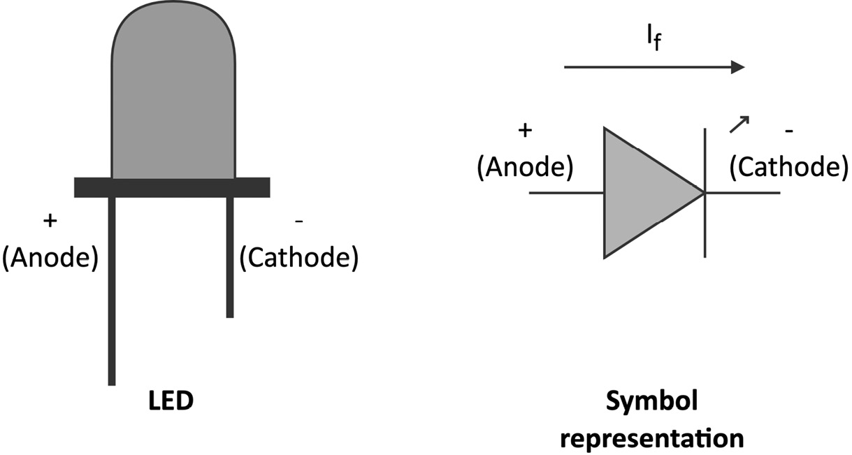
Figure 2.14 – LED with symbolic representation
As mentioned, the LED emits light when the current flows through it. However, in contrast to the resistors, the current flows only in one direction, specifically from the anode to the cathode. This current is commonly called forward current (If).
The brightness of the LED is proportional to If, so the higher it is, the brighter it will appear.
The LED has a maximum operating current that we must not exceed to avoid breaking it instantly. For standard through-hole 5 mm LEDs, the maximum current is typically 20 mA, so values between 4 mA and 15 mA should be enough to see the LED emitting the light.
To allow the current to flow, we need to apply a specific voltage to the terminals' LED, called forward voltage (Vf). We define the Vf as:

We report the typical Vf range for some LED colors in the following table:
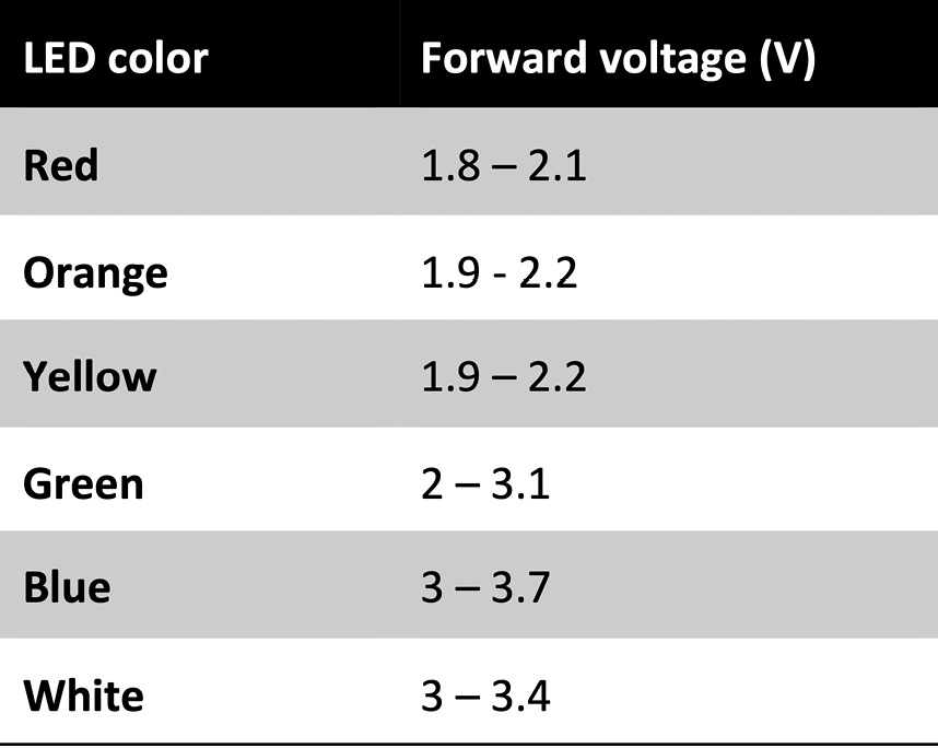
Figure 2.15 – Typical LED forward voltage
From the preceding table, we can observe the following about the forward voltage range:
- It depends on the color.
- It is narrow and less than the typical 3.3 V required to power a microcontroller in most cases.
From these observations, three questions come into mind:
- First, how can we apply the forward voltage on the LED terminals since we typically only have 3.3 V from the microcontroller?
- What happens if we apply a voltage lower than the minimum Vf?
- What happens if we apply a voltage higher than the maximum Vf?
The answers rely on the following physical relationship between the voltage and current of the LED:
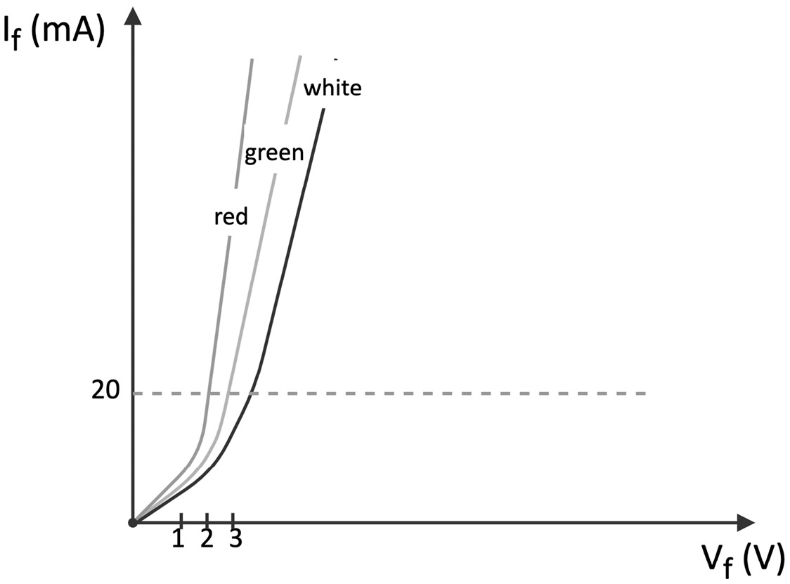
Figure 2.16 – Voltage-current (VI) characteristic of LED
From the previous chart where the x and y axes report the voltage and current, we can deduce the following:
- If we applied a voltage much lower than Vf to the LED, the LED would not turn on because the current would be low.
- If we applied a voltage much higher than Vf on the LED, the LED would be damaged because the current would exceed the 20 mA limit.
Therefore, fixing the voltage at the required operating Vf is crucial to ensure that the device works and is not damaged.
The solution is simple and only requires a resistor in series with the LED, as shown in the following figure:
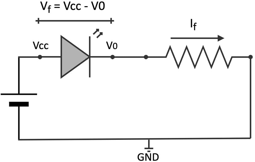
Figure 2.17 – The resistor in series with the LED limits the current
At this point, it should be clear why we included the resistor in the circuit of the previous recipe. Since the LED has a fixed voltage drop when it emits the light (Vf), the resistor limits the current at the value we want, such as 4 mA–15 mA. Therefore, having the LED current in the acceptable range means that the Vf does not fall out of the expected operating range.
We can calculate the resistor's value using the following formula:
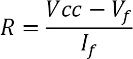
Where:
- Vf is the forward voltage.
- If is the forward current.
- R is the resistance.
The forward voltage/current and LED brightness information is generally available in the LED datasheet.
Now, let's see how we can control the status of this device with the GPIO peripheral.
Introducing the GPIO peripheral
General-purpose input/output (GPIO) is the most common and versatile peripheral on microcontrollers.
As the name suggests, GPIO does not have a fixed functionality. Instead, its primary function is to provide (output) or read (input) digital signals (1 or 0) through the external pins, commonly called either GPIO, IO, or GP.
A microcontroller can integrate several GPIO peripherals, where each one can control a dedicated pin of the integrated chip.
GPIO has similar behavior to std::cout and std::cin of the C++ iostream library but with the difference that it writes and reads fixed voltages rather than characters.
The commonly applied voltages for the logical 1 and 0 levels are as follows:
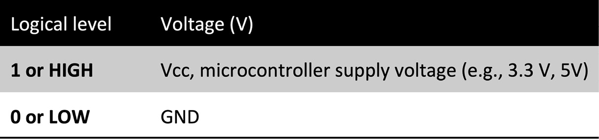
Figure 2.18 – Relation between logical levels and voltages
The LED blinking is a typical example of configuring the GPIO peripheral in output mode to supply either 3.3 V (1) or 0 V (0) programmatically.
There are two ways to connect the LED with the GPIO pin, and the direction of the current makes them different. The first way is current sourcing, where the current flows out of the microcontroller board. To do so, we need to do the following:
- Connect the LED anode to the GPIO pin.
- Connect the LED cathode to the resistor in the series.
- Connect the remaining resistor terminal to GND.
The following circuit shows how to drive an LED with a current sourcing circuit:
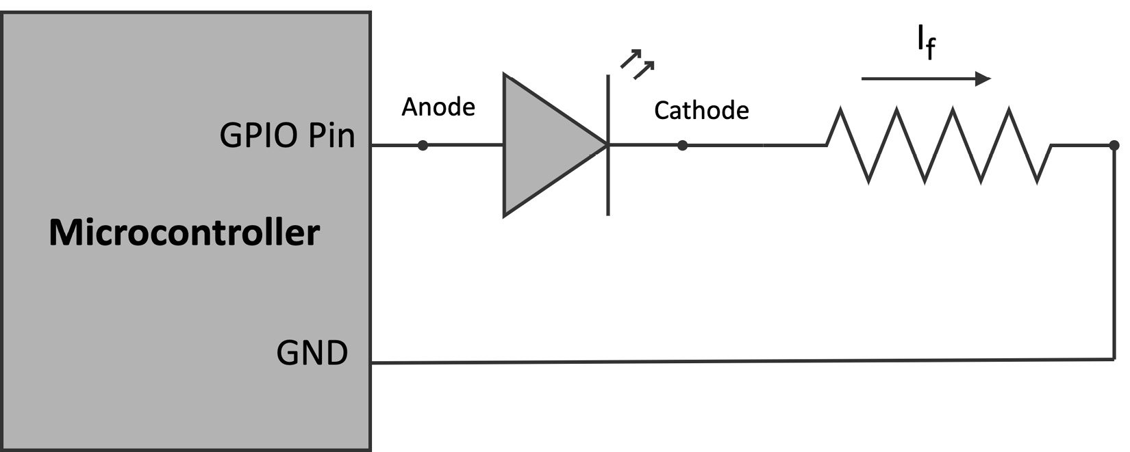
Figure 2.19 – Current sourcing. The current goes out of the microcontroller board
From the preceding circuit, we can observe that the GPIO pin should supply the logical level 1 to turn on the LED.
The second and opposite way is current sinking, where the current flows into the microcontroller board. In this case, we need to do the following:
- Connect the LED cathode to the GPIO pin.
- Connect the LED anode to the resistor in series.
- Connect the remaining resistor terminal to 3.3 V.
As we can observe from the following circuit, the GPIO pin should supply the logical level 0 to turn on the LED:
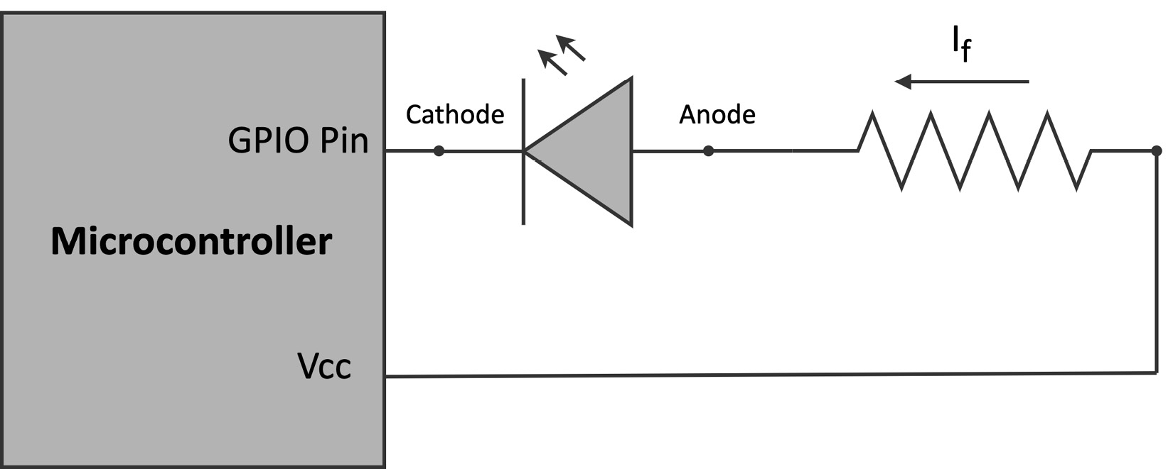
Figure 2.20 – Current sinking. The current goes into the microcontroller board
Whatever solution we adopt, it is essential to keep in mind that the pin has limits on the maximum current, which can be different depending on its direction. For example, the Arduino Nano has a maximum output current of 15 mA and a maximum input current of 5 mA. So, when designing the circuit to drive the LED, we should always consider these limitations for correctly operating and not damaging the device.
How to do it...
Disconnect the microcontroller boards from the power and keep the LED and resistor on the breadboard as in the previous recipe. However, unplug all the jumper wires except the one connected to the - bus rail (GND). The following diagram shows what you should have on the breadboard:
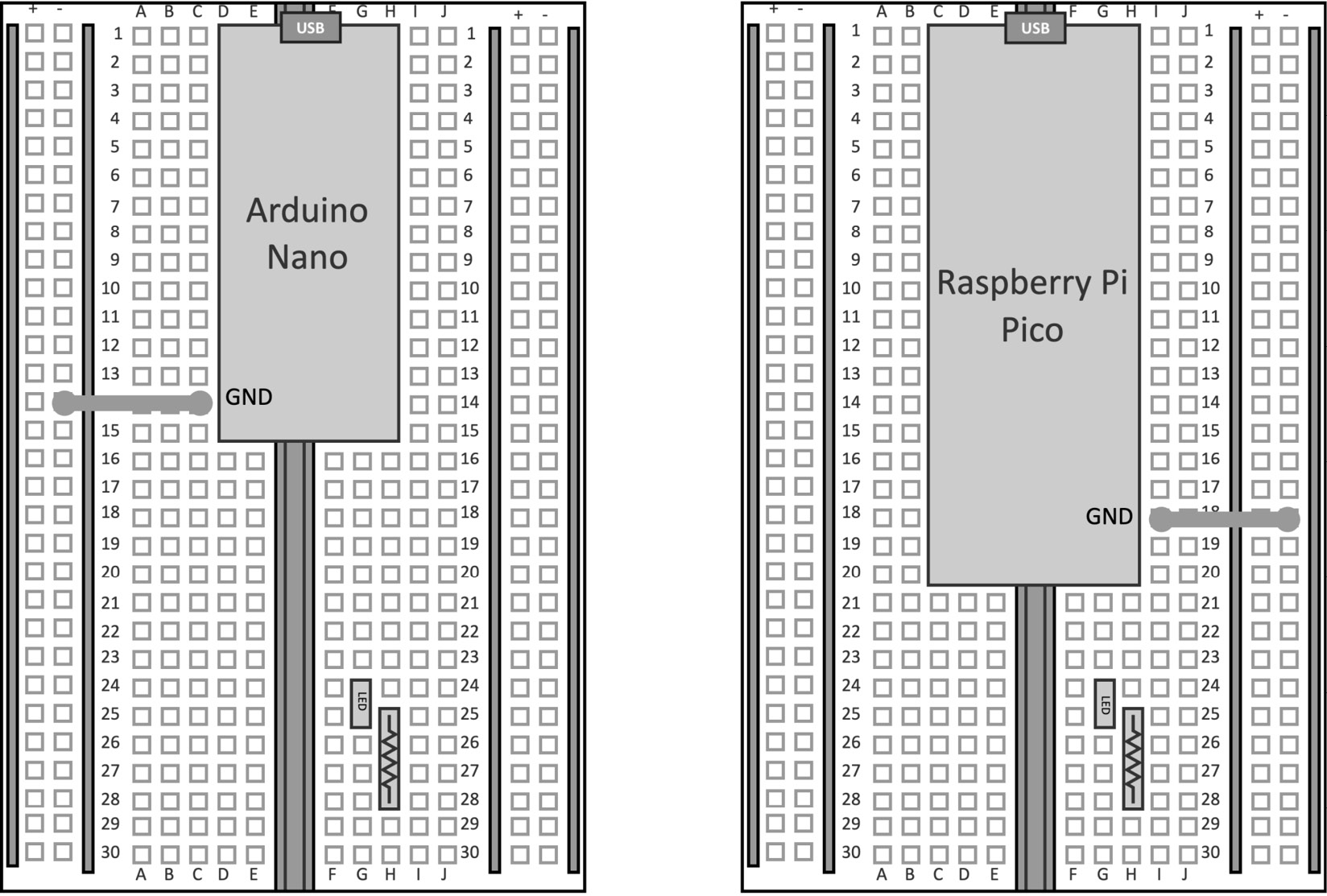
Figure 2.21 – We keep the microcontroller board, LED, and resistor from the Implementing an LED status indicator on the breadboard recipe
Since the LED cathode is connected to the terminal resistor, the LED will be driven by a current sourcing circuit.
The following steps will show how to control the LED light through the GPIO peripheral:
- Choose the GPIO pin to drive the LED. The following table reports our choice:
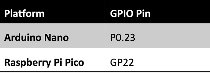
Figure 2.22 – GPIO pin selected for driving the LED
- Connect the LED anode to the GPIO pin with a jumper wire:
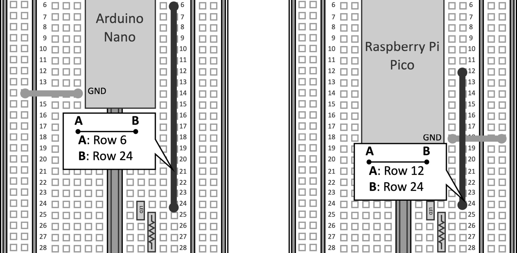
Figure 2.23 – Connect the LED anode to the GPIO pin
On the Arduino Nano, we use a jumper wire to connect (J, 6) with (J, 24). On the Raspberry Pi Pico, we use a jumper wire to connect (J, 12) with (J, 24).
- Connect the terminal resistor to GND:
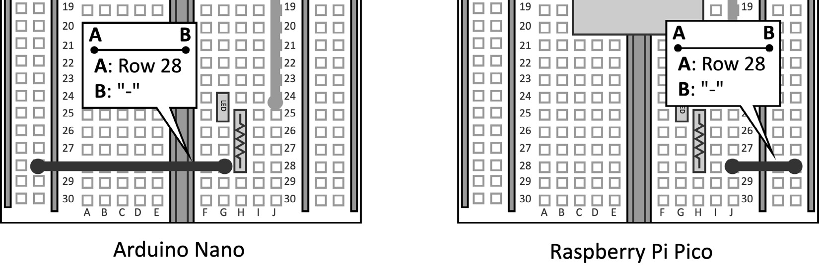
Figure 2.24 – Connect the resistor to GND
On both the Arduino Nano and Raspberry Pi Pico, we connect (J, 28) with the - bus rail.
The 220Ω resistor imposes an LED current of ~5 mA, which is below the maximum 20 mA LED current and below the maximum output GPIO current, as reported in the following table:
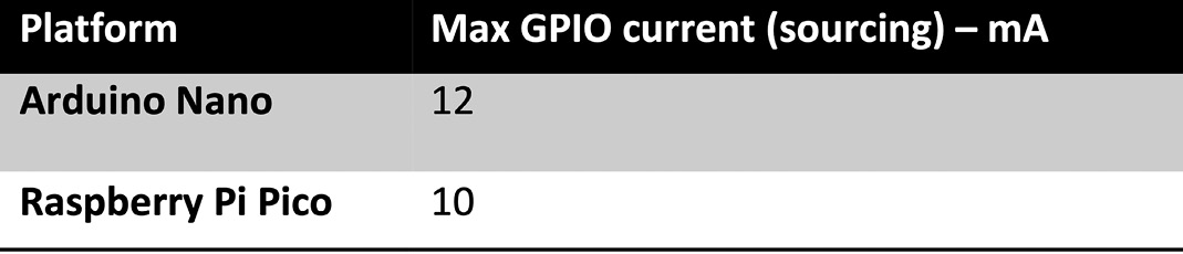
Figure 2.25 – Max GPIO current (sourcing) on the Arduino Nano and Raspberry Pi Pico
Once the circuit is ready, we can focus on the GPIO programming.
- Open the Arduino IDE and create a new sketch. Declare and initialize a global
mbed::DigitalOutobject with the pin name used for driving the LED.
For the Arduino Nano, we have the following:
mbed::DigitalOut led(p23);
And this for the Raspberry Pi Pico:
mbed::DigitalOut led(p22);
Mbed, or rather Mbed OS (https://os.mbed.com/), is a real-time operating system (RTOS) specifically for Arm Cortex-M processors, which offers functionalities typical of a canonical OS and drivers to control microcontroller peripherals. All programs on the Arduino Nano 33 BLE Sense board and Raspberry Pi Pico are built on top of this tiny operating system. In this recipe, we use the mbed::DigitalOutput object (https://os.mbed.com/docs/mbed-os/v6.15/apis/digitalout.html) from Mbed OS to interface with the GPIO peripheral in output mode. The peripheral initialization requires the GPIO pin (PinName) connected to the LED. PinName always starts with the letter p, followed by the pin number.
On the Arduino Nano, the pin number is obtained from the y number reported in the pin label P<x>.<y>. Therefore, PinName is p23.
On the Raspberry Pi Pico, the pin number is obtained from the y number reported in the label GPy. Therefore, PinName is p22.
- Set
ledto1for turning on the LED in theloop()function:void loop() { led = 1; }
Compile the sketch and upload the program to the microcontroller.