
The recipes covered in this chapter include:
- Implementing a vector-based camera model with FPS style input support
- Implementing the free camera
- Implementing target camera
- Implementing the view frustum culling
- Implementing object picking using the depth buffer
- Implementing object picking using color based picking
- Implementing object picking using scene intersection queries
In this chapter, we will look at the recipes for handling 3D viewing tasks and object picking in OpenGL v3.3 and above. All of the real-time simulations, games, and other graphics applications require a virtual camera or a virtual viewer from the point of view of which the 3D scene is rendered. The virtual camera is itself placed in the 3D world and has a specific direction called the camera look direction. Internally, the virtual camera is itself a collection of translations and rotations, which is stored inside the viewing matrix.
We will begin this chapter by designing a simple class to handle the camera. In a typical OpenGL application, the viewing operations are carried out to place a virtual object on screen. We leave the details of the transformations required in between to a typical graduate text on computer graphics like the one given in the See also section of this recipe. This recipe will focus on designing a simple and efficient camera class. We create a simple inheritance from a base class called CAbstractCamera. We will inherit two classes from this parent class, CFreeCamera and CTargetCamera, as shown in the following figure:

We first declare the constructor/destructor pair. Next, the function for setting the projection for the camera is specified. Then some functions for updating the camera matrices based on rotation values are declared. Following these, the accessors and mutators are defined.
- Check for the keyboard key press event.
- If the W or S key is pressed, move the camera in the
lookvector direction:if( GetAsyncKeyState(VK_W) & 0x8000) cam.Walk(dt); if( GetAsyncKeyState(VK_S) & 0x8000) cam.Walk(-dt);
- If the A or D key is pressed, move the camera in the right vector direction:
if( GetAsyncKeyState(VK_A) & 0x8000) cam.Strafe(-dt); if( GetAsyncKeyState(VK_D) & 0x8000) cam.Strafe(dt);
- If the Q or Z key is pressed, move the camera in the up vector direction:
if( GetAsyncKeyState(VK_Q) & 0x8000) cam.Lift(dt); if( GetAsyncKeyState(VK_Z) & 0x8000) cam.Lift(-dt);
For handling mouse events, we attach two callbacks. One for mouse movement and the other for the mouse click event handling:
- Define the mouse down and mouse move event handlers.
- Determine the mouse input choice (the zoom or rotate state) in the mouse down event handler based on the mouse button clicked:
if(button == GLUT_MIDDLE_BUTTON) state = 0; else state = 1;
- If zoom state is chosen, calculate the
fovvalue based on the drag amount and then set up the camera projection matrix:if (state == 0) { fov += (y - oldY)/5.0f; cam.SetupProjection(fov, cam.GetAspectRatio()); } - If the rotate state is chosen, calculate the rotation amount (pitch and yaw). If mouse filtering is enabled, use the filtered mouse input, otherwise use the raw rotation amount:
else { rY += (y - oldY)/5.0f; rX += (oldX-x)/5.0f; if(useFiltering) filterMouseMoves(rX, rY); else { mouseX = rX; mouseY = rY; } cam.Rotate(mouseX,mouseY, 0); }
It is always better to use filtered mouse input, which gives smoother movement. In the recipes, we use a simple average filter of the last 10 inputs weighted based on their temporal distance. So the previous input is given more weight and the 5th latest input is given less weight. The filtered result is used as shown in the following code snippet:
- Smooth mouse filtering FAQ by Paul Nettle (http://www.flipcode.com/archives/Smooth_Mouse_Filtering.shtml)
- Real-time Rendering 3rd Edition by Tomas Akenine-Moller, Eric Haines, and Naty Hoffman, AK Peters/CRC Press, 2008
Chapter2/src directory. The CAbstractCamera class is defined in the AbstractCamera.[h/cpp] files.
declare the constructor/destructor pair. Next, the function for setting the projection for the camera is specified. Then some functions for updating the camera matrices based on rotation values are declared. Following these, the accessors and mutators are defined.
- Check for the keyboard key press event.
- If the W or S key is pressed, move the camera in the
lookvector direction:if( GetAsyncKeyState(VK_W) & 0x8000) cam.Walk(dt); if( GetAsyncKeyState(VK_S) & 0x8000) cam.Walk(-dt);
- If the A or D key is pressed, move the camera in the right vector direction:
if( GetAsyncKeyState(VK_A) & 0x8000) cam.Strafe(-dt); if( GetAsyncKeyState(VK_D) & 0x8000) cam.Strafe(dt);
- If the Q or Z key is pressed, move the camera in the up vector direction:
if( GetAsyncKeyState(VK_Q) & 0x8000) cam.Lift(dt); if( GetAsyncKeyState(VK_Z) & 0x8000) cam.Lift(-dt);
For handling mouse events, we attach two callbacks. One for mouse movement and the other for the mouse click event handling:
- Define the mouse down and mouse move event handlers.
- Determine the mouse input choice (the zoom or rotate state) in the mouse down event handler based on the mouse button clicked:
if(button == GLUT_MIDDLE_BUTTON) state = 0; else state = 1;
- If zoom state is chosen, calculate the
fovvalue based on the drag amount and then set up the camera projection matrix:if (state == 0) { fov += (y - oldY)/5.0f; cam.SetupProjection(fov, cam.GetAspectRatio()); } - If the rotate state is chosen, calculate the rotation amount (pitch and yaw). If mouse filtering is enabled, use the filtered mouse input, otherwise use the raw rotation amount:
else { rY += (y - oldY)/5.0f; rX += (oldX-x)/5.0f; if(useFiltering) filterMouseMoves(rX, rY); else { mouseX = rX; mouseY = rY; } cam.Rotate(mouseX,mouseY, 0); }
It is always better to use filtered mouse input, which gives smoother movement. In the recipes, we use a simple average filter of the last 10 inputs weighted based on their temporal distance. So the previous input is given more weight and the 5th latest input is given less weight. The filtered result is used as shown in the following code snippet:
- Smooth mouse filtering FAQ by Paul Nettle (http://www.flipcode.com/archives/Smooth_Mouse_Filtering.shtml)
- Real-time Rendering 3rd Edition by Tomas Akenine-Moller, Eric Haines, and Naty Hoffman, AK Peters/CRC Press, 2008
CAbstractCamera class. Instead, we will use either the CFreeCamera class or the CTargetCamera class, as detailed in the following recipes. In this recipe, we will see how to handle input using the mouse and keyboard.
look vector direction:if( GetAsyncKeyState(VK_W) & 0x8000) cam.Walk(dt); if( GetAsyncKeyState(VK_S) & 0x8000) cam.Walk(-dt);
if( GetAsyncKeyState(VK_A) & 0x8000) cam.Strafe(-dt); if( GetAsyncKeyState(VK_D) & 0x8000) cam.Strafe(dt);
if( GetAsyncKeyState(VK_Q) & 0x8000) cam.Lift(dt); if( GetAsyncKeyState(VK_Z) & 0x8000) cam.Lift(-dt);
handling mouse events, we attach two callbacks. One for mouse movement and the other for the mouse click event handling:
- Define the mouse down and mouse move event handlers.
- Determine the mouse input choice (the zoom or rotate state) in the mouse down event handler based on the mouse button clicked:
if(button == GLUT_MIDDLE_BUTTON) state = 0; else state = 1;
- If zoom state is chosen, calculate the
fovvalue based on the drag amount and then set up the camera projection matrix:if (state == 0) { fov += (y - oldY)/5.0f; cam.SetupProjection(fov, cam.GetAspectRatio()); } - If the rotate state is chosen, calculate the rotation amount (pitch and yaw). If mouse filtering is enabled, use the filtered mouse input, otherwise use the raw rotation amount:
else { rY += (y - oldY)/5.0f; rX += (oldX-x)/5.0f; if(useFiltering) filterMouseMoves(rX, rY); else { mouseX = rX; mouseY = rY; } cam.Rotate(mouseX,mouseY, 0); }
It is always better to use filtered mouse input, which gives smoother movement. In the recipes, we use a simple average filter of the last 10 inputs weighted based on their temporal distance. So the previous input is given more weight and the 5th latest input is given less weight. The filtered result is used as shown in the following code snippet:
- Smooth mouse filtering FAQ by Paul Nettle (http://www.flipcode.com/archives/Smooth_Mouse_Filtering.shtml)
- Real-time Rendering 3rd Edition by Tomas Akenine-Moller, Eric Haines, and Naty Hoffman, AK Peters/CRC Press, 2008
always better to use filtered mouse input, which gives smoother movement. In the recipes, we use a simple average filter of the last 10 inputs weighted based on their temporal distance. So the previous input is given more weight and the 5th latest input is given less weight. The filtered result is used as shown in the following code snippet:
- Smooth mouse filtering FAQ by Paul Nettle (http://www.flipcode.com/archives/Smooth_Mouse_Filtering.shtml)
- Real-time Rendering 3rd Edition by Tomas Akenine-Moller, Eric Haines, and Naty Hoffman, AK Peters/CRC Press, 2008
- FAQ by Paul Nettle (http://www.flipcode.com/archives/Smooth_Mouse_Filtering.shtml)
- Real-time Rendering 3rd Edition by Tomas Akenine-Moller, Eric Haines, and Naty Hoffman, AK Peters/CRC Press, 2008
Free camera is the first camera type which we will implement in this recipe. A free camera does not have a fixed target. However it does have a fixed position from which it can look in any direction.
The following figure shows a free viewing camera. When we rotate the camera, it rotates at its position. When we move the camera, it keeps looking in the same direction.

The steps needed to implement the free camera are as follows:
- Define the
CFreeCameraclass and add a vector to store the current translation. - In the
Updatemethod, calculate the new orientation (rotation) matrix, using the current camera orientations (that is, yaw, pitch, and roll amount):glm::mat4 R = glm::yawPitchRoll(yaw,pitch,roll);
- Translate the camera position by the translation amount:
position+=translation;
If we need to implement a free camera which gradually comes to a halt, we should gradually decay the translation vector by adding the following code after the key events are handled:
glm::vec3 t = cam.GetTranslation(); if(glm::dot(t,t)>EPSILON2) { cam.SetTranslation(t*0.95f); }If no decay is needed, then we should clear the translation vector to
0in theCFreeCamera::Updatefunction after translating the position:translation = glm::vec3(0);
- Transform the
lookvector by the current rotation matrix, and determine therightandupvectors to calculate the orthonormal basis:look = glm::vec3(R*glm::vec4(0,0,1,0)); up = glm::vec3(R*glm::vec4(0,1,0,0)); right = glm::cross(look, up);
- Determine the camera target point:
glm::vec3 tgt = position+look;
- Use the
glm::lookatfunction to calculate the new view matrix using the camera position, target, and theupvector:V = glm::lookAt(position, tgt, up);
The Walk function simply translates the camera in the look direction:
The Strafe function translates the camera in the right direction:
The Lift function translates the camera in the up direction:

- DHPOWare OpenGL camera demo – Part 1 (http://www.dhpoware.com/demos/glCamera1.html)
- DHPOWare OpenGL camera demo – Part 2 (http://www.dhpoware.com/demos/glCamera2.html)
- DHPOWare OpenGL camera demo – Part 3 (http://www.dhpoware.com/demos/glCamera3.html)
The steps needed to implement the free camera are as follows:
- Define the
CFreeCameraclass and add a vector to store the current translation. - In the
Updatemethod, calculate the new orientation (rotation) matrix, using the current camera orientations (that is, yaw, pitch, and roll amount):glm::mat4 R = glm::yawPitchRoll(yaw,pitch,roll);
- Translate the camera position by the translation amount:
position+=translation;
If we need to implement a free camera which gradually comes to a halt, we should gradually decay the translation vector by adding the following code after the key events are handled:
glm::vec3 t = cam.GetTranslation(); if(glm::dot(t,t)>EPSILON2) { cam.SetTranslation(t*0.95f); }If no decay is needed, then we should clear the translation vector to
0in theCFreeCamera::Updatefunction after translating the position:translation = glm::vec3(0);
- Transform the
lookvector by the current rotation matrix, and determine therightandupvectors to calculate the orthonormal basis:look = glm::vec3(R*glm::vec4(0,0,1,0)); up = glm::vec3(R*glm::vec4(0,1,0,0)); right = glm::cross(look, up);
- Determine the camera target point:
glm::vec3 tgt = position+look;
- Use the
glm::lookatfunction to calculate the new view matrix using the camera position, target, and theupvector:V = glm::lookAt(position, tgt, up);
The Walk function simply translates the camera in the look direction:
The Strafe function translates the camera in the right direction:
The Lift function translates the camera in the up direction:
- DHPOWare OpenGL camera demo – Part 1 (http://www.dhpoware.com/demos/glCamera1.html)
- DHPOWare OpenGL camera demo – Part 2 (http://www.dhpoware.com/demos/glCamera2.html)
- DHPOWare OpenGL camera demo – Part 3 (http://www.dhpoware.com/demos/glCamera3.html)
CFreeCamera class and add a vector to store the current translation.
Update method, calculate the new orientation (rotation) matrix, using the current camera orientations (that is, yaw, pitch, and roll amount):glm::mat4 R = glm::yawPitchRoll(yaw,pitch,roll);
- Translate the camera position by the translation amount:
position+=translation;
If we need to implement a free camera which gradually comes to a halt, we should gradually decay the translation vector by adding the following code after the key events are handled:
glm::vec3 t = cam.GetTranslation(); if(glm::dot(t,t)>EPSILON2) { cam.SetTranslation(t*0.95f); }If no decay is needed, then we should clear the translation vector to
0in theCFreeCamera::Updatefunction after translating the position:translation = glm::vec3(0);
- Transform the
lookvector by the current rotation matrix, and determine therightandupvectors to calculate the orthonormal basis:look = glm::vec3(R*glm::vec4(0,0,1,0)); up = glm::vec3(R*glm::vec4(0,1,0,0)); right = glm::cross(look, up);
- Determine the camera target point:
glm::vec3 tgt = position+look;
- Use the
glm::lookatfunction to calculate the new view matrix using the camera position, target, and theupvector:V = glm::lookAt(position, tgt, up);
The Walk function simply translates the camera in the look direction:
The Strafe function translates the camera in the right direction:
The Lift function translates the camera in the up direction:
- DHPOWare OpenGL camera demo – Part 1 (http://www.dhpoware.com/demos/glCamera1.html)
- DHPOWare OpenGL camera demo – Part 2 (http://www.dhpoware.com/demos/glCamera2.html)
- DHPOWare OpenGL camera demo – Part 3 (http://www.dhpoware.com/demos/glCamera3.html)
Walk function
simply translates the camera in the look direction:
The Strafe function translates the camera in the right direction:
The Lift function translates the camera in the up direction:
- DHPOWare OpenGL camera demo – Part 1 (http://www.dhpoware.com/demos/glCamera1.html)
- DHPOWare OpenGL camera demo – Part 2 (http://www.dhpoware.com/demos/glCamera2.html)
- DHPOWare OpenGL camera demo – Part 3 (http://www.dhpoware.com/demos/glCamera3.html)
- http://www.dhpoware.com/demos/glCamera1.html)
- DHPOWare OpenGL camera demo – Part 2 (http://www.dhpoware.com/demos/glCamera2.html)
- DHPOWare OpenGL camera demo – Part 3 (http://www.dhpoware.com/demos/glCamera3.html)
The target camera works the opposite way. Rather than the position, the target remains fixed, while the camera moves or rotates around the target. Some operations like panning, move both the target and the camera position together.
The following figure shows an illustration of a target camera. Note that the small box is the target position for the camera.

The code for this recipe resides in the Chapter2/TargetCamera directory. The CTargetCamera class is defined in the Chapter2/src/TargetCamera.[h/cpp] files. The class declaration is as follows:
We implement the target camera as follows:
- Define the
CTargetCameraclass with a target position (target), the rotation limits (minRyandmaxRy), the distance between the target and the camera position (distance), and the distance limits (minDistanceandmaxDistance). - In the
Updatemethod, calculate the new orientation (rotation) matrix using the current camera orientations (that is, yaw, pitch, and roll amount):glm::mat4 R = glm::yawPitchRoll(yaw,pitch,roll);
- Use the distance to get a vector and then translate this vector by the current rotation matrix:
glm::vec3 T = glm::vec3(0,0,distance); T = glm::vec3(R*glm::vec4(T,0.0f));
- Get the new camera position by adding the translation vector to the target position:
position = target + T;
- Recalculate the orthonormal basis and then the view matrix:
look = glm::normalize(target-position); up = glm::vec3(R*glm::vec4(UP,0.0f)); right = glm::cross(look, up); V = glm::lookAt(position, target, up);
The Move function moves both the position and target by the same amount in both look and right vector directions.
The Pan function moves in the xy plane only, hence the up vector is used instead of the look vector:
The Zoom function moves the position in the look direction:
The demonstration for this recipe renders an infinite checkered plane, as in the previous recipe, and is shown in the following figure:

- DHPOWare OpenGL camera demo – Part 1 (http://www.dhpoware.com/demos/glCamera1.html)
- DHPOWare OpenGL camera demo – Part 2 (http://www.dhpoware.com/demos/glCamera2.html)
- DHPOWare OpenGL camera demo – Part 3 (http://www.dhpoware.com/demos/glCamera3.html)
The code for this recipe resides in the Chapter2/TargetCamera directory. The CTargetCamera class is defined in the Chapter2/src/TargetCamera.[h/cpp] files. The class declaration is as follows:
We implement the target camera as follows:
- Define the
CTargetCameraclass with a target position (target), the rotation limits (minRyandmaxRy), the distance between the target and the camera position (distance), and the distance limits (minDistanceandmaxDistance). - In the
Updatemethod, calculate the new orientation (rotation) matrix using the current camera orientations (that is, yaw, pitch, and roll amount):glm::mat4 R = glm::yawPitchRoll(yaw,pitch,roll);
- Use the distance to get a vector and then translate this vector by the current rotation matrix:
glm::vec3 T = glm::vec3(0,0,distance); T = glm::vec3(R*glm::vec4(T,0.0f));
- Get the new camera position by adding the translation vector to the target position:
position = target + T;
- Recalculate the orthonormal basis and then the view matrix:
look = glm::normalize(target-position); up = glm::vec3(R*glm::vec4(UP,0.0f)); right = glm::cross(look, up); V = glm::lookAt(position, target, up);
The Move function moves both the position and target by the same amount in both look and right vector directions.
The Pan function moves in the xy plane only, hence the up vector is used instead of the look vector:
The Zoom function moves the position in the look direction:
The demonstration for this recipe renders an infinite checkered plane, as in the previous recipe, and is shown in the following figure:
- DHPOWare OpenGL camera demo – Part 1 (http://www.dhpoware.com/demos/glCamera1.html)
- DHPOWare OpenGL camera demo – Part 2 (http://www.dhpoware.com/demos/glCamera2.html)
- DHPOWare OpenGL camera demo – Part 3 (http://www.dhpoware.com/demos/glCamera3.html)
CTargetCamera class with a target position (target), the rotation limits (minRy and maxRy), the distance between the target and the camera position (distance), and the distance limits (minDistance and maxDistance).
Update method, calculate the new orientation (rotation) matrix using the current camera orientations (that is, yaw, pitch, and roll amount):glm::mat4 R = glm::yawPitchRoll(yaw,pitch,roll);
glm::vec3 T = glm::vec3(0,0,distance); T = glm::vec3(R*glm::vec4(T,0.0f));
position = target + T;
The Move function moves both the position and target by the same amount in both look and right vector directions.
The Pan function moves in the xy plane only, hence the up vector is used instead of the look vector:
The Zoom function moves the position in the look direction:
The demonstration for this recipe renders an infinite checkered plane, as in the previous recipe, and is shown in the following figure:
- DHPOWare OpenGL camera demo – Part 1 (http://www.dhpoware.com/demos/glCamera1.html)
- DHPOWare OpenGL camera demo – Part 2 (http://www.dhpoware.com/demos/glCamera2.html)
- DHPOWare OpenGL camera demo – Part 3 (http://www.dhpoware.com/demos/glCamera3.html)
Move function
moves both the position and target by the same amount in both look and right vector directions.
The Pan function moves in the xy plane only, hence the up vector is used instead of the look vector:
The Zoom function moves the position in the look direction:
The demonstration for this recipe renders an infinite checkered plane, as in the previous recipe, and is shown in the following figure:
- DHPOWare OpenGL camera demo – Part 1 (http://www.dhpoware.com/demos/glCamera1.html)
- DHPOWare OpenGL camera demo – Part 2 (http://www.dhpoware.com/demos/glCamera2.html)
- DHPOWare OpenGL camera demo – Part 3 (http://www.dhpoware.com/demos/glCamera3.html)
- http://www.dhpoware.com/demos/glCamera1.html)
- DHPOWare OpenGL camera demo – Part 2 (http://www.dhpoware.com/demos/glCamera2.html)
- DHPOWare OpenGL camera demo – Part 3 (http://www.dhpoware.com/demos/glCamera3.html)
When working with a lot of polygonal data, there is a need to reduce the amount of geometry pushed to the GPU for processing. There are several techniques for scene management, such as quadtrees, octrees, and bsp trees. These techniques help in sorting the geometry in visibility order, so that the objects are sorted (and some of these even culled from the display). This helps in reducing the work load on the GPU.
Even before such techniques can be used, there is an additional step which most graphics applications do and that is view frustum culling. This process removes the geometry if it is not in the current camera's view frustum. The idea is that if the object is not viewable, it should not be processed. A frustum is a chopped pyramid with its tip at the camera position and the base is at the far clip plane. The near clip plane is where the pyramid is chopped, as shown in the following figure. Any geometry inside the viewing frustum is displayed.

We will implement view frustum culling by taking the following steps:
- Define a vertex shader that displaces the object-space vertex position using a sine wave in the y axis:
#version 330 core layout(location = 0) in vec3 vVertex; uniform float t; const float PI = 3.141562; void main() { gl_Position=vec4(vVertex,1)+vec4(0,sin(vVertex.x*2*PI+t),0,0); } - Define a geometry shader that performs the view frustum culling calculation on each vertex passed in from the vertex shader:
#version 330 core layout (points) in; layout (points, max_vertices=3) out; uniform mat4 MVP; uniform vec4 FrustumPlanes[6]; bool PointInFrustum(in vec3 p) { for(int i=0; i < 6; i++) { vec4 plane=FrustumPlanes[i]; if ((dot(plane.xyz, p)+plane.w) < 0) return false; } return true; } void main() { //get the basic vertices for(int i=0;i<gl_in.length(); i++) { vec4 vInPos = gl_in[i].gl_Position; vec2 tmp = (vInPos.xz*2-1.0)*5; vec3 V = vec3(tmp.x, vInPos.y, tmp.y); gl_Position = MVP*vec4(V,1); if(PointInFrustum(V)) { EmitVertex(); } } EndPrimitive(); } - To render particles as rounded points, we do a simple trigonometric calculation by discarding all fragments that fall outside the radius of the circle:
#version 330 core layout(location = 0) out vec4 vFragColor; void main() { vec2 pos = (gl_PointCoord.xy-0.5); if(0.25<dot(pos,pos)) discard; vFragColor = vec4(0,0,1,1); } - On the CPU side, call the
CAbstractCamera::CalcFrustumPlanes()function to calculate the viewing frustum planes. Get the calculated frustum planes as aglm::vec4array by callingCAbstractCamera::GetFrustumPlanes(), and then pass these to the shader. Thexyzcomponents store the plane's normal, and thewcoordinate stores the distance of the plane. After these calls we draw the points:pCurrentCam->CalcFrustumPlanes(); glm::vec4 p[6]; pCurrentCam->GetFrustumPlanes(p); pointShader.Use(); glUniform1f(pointShader("t"), current_time); glUniformMatrix4fv(pointShader("MVP"), 1, GL_FALSE, glm::value_ptr(MVP)); glUniform4fv(pointShader("FrustumPlanes"), 6, glm::value_ptr(p[0])); glBindVertexArray(pointVAOID); glDrawArrays(GL_POINTS,0,MAX_POINTS); pointShader.UnUse();
There are two main parts of this recipe: calculation of the viewing frustum planes and checking if a given point is in the viewing frustum. The first calculation is carried out in the CAbstractCamera::CalcFrustumPlanes() function. Refer to the Chapter2/src/AbstractCamera.cpp files for details.
This function iterates through all of the six frustum planes. In each iteration, it checks the signed distance of the given point p with respect to the ith frustum plane. This is a simple dot product of the plane normal with the given point and adding the plane distance. If the signed distance is negative for any of the planes, the point is outside the viewing frustum so we can safely reject the point. If the point has a positive signed distance for all of the six frustum planes, it is inside the viewing frustum. Note that the frustum planes are oriented in such a way that their normals point inside the viewing frustum.
Chapter2/ViewFrustumCulling directory.
We will implement view frustum culling by taking the following steps:
- Define a vertex shader that displaces the object-space vertex position using a sine wave in the y axis:
#version 330 core layout(location = 0) in vec3 vVertex; uniform float t; const float PI = 3.141562; void main() { gl_Position=vec4(vVertex,1)+vec4(0,sin(vVertex.x*2*PI+t),0,0); } - Define a geometry shader that performs the view frustum culling calculation on each vertex passed in from the vertex shader:
#version 330 core layout (points) in; layout (points, max_vertices=3) out; uniform mat4 MVP; uniform vec4 FrustumPlanes[6]; bool PointInFrustum(in vec3 p) { for(int i=0; i < 6; i++) { vec4 plane=FrustumPlanes[i]; if ((dot(plane.xyz, p)+plane.w) < 0) return false; } return true; } void main() { //get the basic vertices for(int i=0;i<gl_in.length(); i++) { vec4 vInPos = gl_in[i].gl_Position; vec2 tmp = (vInPos.xz*2-1.0)*5; vec3 V = vec3(tmp.x, vInPos.y, tmp.y); gl_Position = MVP*vec4(V,1); if(PointInFrustum(V)) { EmitVertex(); } } EndPrimitive(); } - To render particles as rounded points, we do a simple trigonometric calculation by discarding all fragments that fall outside the radius of the circle:
#version 330 core layout(location = 0) out vec4 vFragColor; void main() { vec2 pos = (gl_PointCoord.xy-0.5); if(0.25<dot(pos,pos)) discard; vFragColor = vec4(0,0,1,1); } - On the CPU side, call the
CAbstractCamera::CalcFrustumPlanes()function to calculate the viewing frustum planes. Get the calculated frustum planes as aglm::vec4array by callingCAbstractCamera::GetFrustumPlanes(), and then pass these to the shader. Thexyzcomponents store the plane's normal, and thewcoordinate stores the distance of the plane. After these calls we draw the points:pCurrentCam->CalcFrustumPlanes(); glm::vec4 p[6]; pCurrentCam->GetFrustumPlanes(p); pointShader.Use(); glUniform1f(pointShader("t"), current_time); glUniformMatrix4fv(pointShader("MVP"), 1, GL_FALSE, glm::value_ptr(MVP)); glUniform4fv(pointShader("FrustumPlanes"), 6, glm::value_ptr(p[0])); glBindVertexArray(pointVAOID); glDrawArrays(GL_POINTS,0,MAX_POINTS); pointShader.UnUse();
There are two main parts of this recipe: calculation of the viewing frustum planes and checking if a given point is in the viewing frustum. The first calculation is carried out in the CAbstractCamera::CalcFrustumPlanes() function. Refer to the Chapter2/src/AbstractCamera.cpp files for details.
This function iterates through all of the six frustum planes. In each iteration, it checks the signed distance of the given point p with respect to the ith frustum plane. This is a simple dot product of the plane normal with the given point and adding the plane distance. If the signed distance is negative for any of the planes, the point is outside the viewing frustum so we can safely reject the point. If the point has a positive signed distance for all of the six frustum planes, it is inside the viewing frustum. Note that the frustum planes are oriented in such a way that their normals point inside the viewing frustum.
#version 330 core
layout(location = 0) in vec3 vVertex;
uniform float t;
const float PI = 3.141562;
void main()
{
gl_Position=vec4(vVertex,1)+vec4(0,sin(vVertex.x*2*PI+t),0,0);
}- geometry shader that performs the view frustum culling calculation on each vertex passed in from the vertex shader:
#version 330 core layout (points) in; layout (points, max_vertices=3) out; uniform mat4 MVP; uniform vec4 FrustumPlanes[6]; bool PointInFrustum(in vec3 p) { for(int i=0; i < 6; i++) { vec4 plane=FrustumPlanes[i]; if ((dot(plane.xyz, p)+plane.w) < 0) return false; } return true; } void main() { //get the basic vertices for(int i=0;i<gl_in.length(); i++) { vec4 vInPos = gl_in[i].gl_Position; vec2 tmp = (vInPos.xz*2-1.0)*5; vec3 V = vec3(tmp.x, vInPos.y, tmp.y); gl_Position = MVP*vec4(V,1); if(PointInFrustum(V)) { EmitVertex(); } } EndPrimitive(); } - To render particles as rounded points, we do a simple trigonometric calculation by discarding all fragments that fall outside the radius of the circle:
#version 330 core layout(location = 0) out vec4 vFragColor; void main() { vec2 pos = (gl_PointCoord.xy-0.5); if(0.25<dot(pos,pos)) discard; vFragColor = vec4(0,0,1,1); } - On the CPU side, call the
CAbstractCamera::CalcFrustumPlanes()function to calculate the viewing frustum planes. Get the calculated frustum planes as aglm::vec4array by callingCAbstractCamera::GetFrustumPlanes(), and then pass these to the shader. Thexyzcomponents store the plane's normal, and thewcoordinate stores the distance of the plane. After these calls we draw the points:pCurrentCam->CalcFrustumPlanes(); glm::vec4 p[6]; pCurrentCam->GetFrustumPlanes(p); pointShader.Use(); glUniform1f(pointShader("t"), current_time); glUniformMatrix4fv(pointShader("MVP"), 1, GL_FALSE, glm::value_ptr(MVP)); glUniform4fv(pointShader("FrustumPlanes"), 6, glm::value_ptr(p[0])); glBindVertexArray(pointVAOID); glDrawArrays(GL_POINTS,0,MAX_POINTS); pointShader.UnUse();
There are two main parts of this recipe: calculation of the viewing frustum planes and checking if a given point is in the viewing frustum. The first calculation is carried out in the CAbstractCamera::CalcFrustumPlanes() function. Refer to the Chapter2/src/AbstractCamera.cpp files for details.
This function iterates through all of the six frustum planes. In each iteration, it checks the signed distance of the given point p with respect to the ith frustum plane. This is a simple dot product of the plane normal with the given point and adding the plane distance. If the signed distance is negative for any of the planes, the point is outside the viewing frustum so we can safely reject the point. If the point has a positive signed distance for all of the six frustum planes, it is inside the viewing frustum. Note that the frustum planes are oriented in such a way that their normals point inside the viewing frustum.
This function iterates through all of the six frustum planes. In each iteration, it checks the signed distance of the given point p with respect to the ith frustum plane. This is a simple dot product of the plane normal with the given point and adding the plane distance. If the signed distance is negative for any of the planes, the point is outside the viewing frustum so we can safely reject the point. If the point has a positive signed distance for all of the six frustum planes, it is inside the viewing frustum. Note that the frustum planes are oriented in such a way that their normals point inside the viewing frustum.


Often when working on projects, we need the ability to pick graphical objects on screen. While in OpenGL versions before OpenGL 3.0, the selection buffer was used for this purpose, this buffer is removed in the modern OpenGL 3.3 core profile. However, this leaves us with some alternate methods. We will implement a simple picking technique using the depth buffer in this recipe.
Picking using depth buffer can be implemented as follows:
- Enable depth testing:
glEnable(GL_DEPTH_TEST);
- In the mouse down event handler, read the depth value from the depth buffer using the
glReadPixelsfunction at the clicked point:glReadPixels( x, HEIGHT-y, 1, 1, GL_DEPTH_COMPONENT, GL_FLOAT, &winZ);
- Unproject the 3D point,
vec3(x,HEIGHT-y,winZ), to obtain the object-space point from the clicked screen-space pointx,yand the depth valuewinZ. Make sure to invert theyvalue by subtractingHEIGHTfrom the screen-spaceyvalue:glm::vec3 objPt = glm::unProject(glm::vec3(x,HEIGHT-y,winZ), MV, P, glm::vec4(0,0,WIDTH, HEIGHT));
- Check the distances of all of the scene objects from the object-space point
objPt. If the distance is within the bounds of the object and the distance of the object is the nearest to the camera, store the index of the object:size_t i=0; float minDist = 1000; selected_box=-1; for(i=0;i<3;i++) { float dist = glm::distance(box_positions[i], objPt); if( dist<1 && dist<minDist) { selected_box = i; minDist = dist; } } - Based on the selected index, color the object as selected:
glm::mat4 T = glm::translate(glm::mat4(1), box_positions[0]); cube->color = (selected_box==0)?glm::vec3(0,1,1):glm::vec3(1,0,0); cube->Render(glm::value_ptr(MVP*T)); T = glm::translate(glm::mat4(1), box_positions[1]); cube->color = (selected_box==1)?glm::vec3(0,1,1):glm::vec3(0,1,0); cube->Render(glm::value_ptr(MVP*T)); T = glm::translate(glm::mat4(1), box_positions[2]); cube->color = (selected_box==2)?glm::vec3(0,1,1):glm::vec3(0,0,1); cube->Render(glm::value_ptr(MVP*T));
This recipe renders three cubes in red, green, and blue on the screen. When the user clicks on any of these cubes, the depth buffer is read to find the depth value at the clicked point. The object-space point is then obtained by unprojecting (glm::unProject) the clicked point (x,HEIGHT-y, winZ). A loop is then iterated over all objects in the scene to find the nearest object to the object-space point. The index of the nearest intersected object is then stored.
Chapter2/Picking_DepthBuffer folder. Relevant source files are in the Chapter2/src folder.
Picking using depth buffer can be implemented as follows:
- Enable depth testing:
glEnable(GL_DEPTH_TEST);
- In the mouse down event handler, read the depth value from the depth buffer using the
glReadPixelsfunction at the clicked point:glReadPixels( x, HEIGHT-y, 1, 1, GL_DEPTH_COMPONENT, GL_FLOAT, &winZ);
- Unproject the 3D point,
vec3(x,HEIGHT-y,winZ), to obtain the object-space point from the clicked screen-space pointx,yand the depth valuewinZ. Make sure to invert theyvalue by subtractingHEIGHTfrom the screen-spaceyvalue:glm::vec3 objPt = glm::unProject(glm::vec3(x,HEIGHT-y,winZ), MV, P, glm::vec4(0,0,WIDTH, HEIGHT));
- Check the distances of all of the scene objects from the object-space point
objPt. If the distance is within the bounds of the object and the distance of the object is the nearest to the camera, store the index of the object:size_t i=0; float minDist = 1000; selected_box=-1; for(i=0;i<3;i++) { float dist = glm::distance(box_positions[i], objPt); if( dist<1 && dist<minDist) { selected_box = i; minDist = dist; } } - Based on the selected index, color the object as selected:
glm::mat4 T = glm::translate(glm::mat4(1), box_positions[0]); cube->color = (selected_box==0)?glm::vec3(0,1,1):glm::vec3(1,0,0); cube->Render(glm::value_ptr(MVP*T)); T = glm::translate(glm::mat4(1), box_positions[1]); cube->color = (selected_box==1)?glm::vec3(0,1,1):glm::vec3(0,1,0); cube->Render(glm::value_ptr(MVP*T)); T = glm::translate(glm::mat4(1), box_positions[2]); cube->color = (selected_box==2)?glm::vec3(0,1,1):glm::vec3(0,0,1); cube->Render(glm::value_ptr(MVP*T));
This recipe renders three cubes in red, green, and blue on the screen. When the user clicks on any of these cubes, the depth buffer is read to find the depth value at the clicked point. The object-space point is then obtained by unprojecting (glm::unProject) the clicked point (x,HEIGHT-y, winZ). A loop is then iterated over all objects in the scene to find the nearest object to the object-space point. The index of the nearest intersected object is then stored.
glEnable(GL_DEPTH_TEST);
glReadPixels function at the clicked point:glReadPixels( x, HEIGHT-y, 1, 1, GL_DEPTH_COMPONENT, GL_FLOAT, &winZ);
vec3(x,HEIGHT-y,winZ), to obtain the object-space point from the clicked screen-space point x,y and the depth value winZ. Make sure to invert the y value by subtracting HEIGHT from the screen-space y value:glm::vec3 objPt = glm::unProject(glm::vec3(x,HEIGHT-y,winZ), MV, P, glm::vec4(0,0,WIDTH, HEIGHT));
objPt. If the distance is within the bounds of the object and the distance of the object is the nearest to the camera, store the index of the object:size_t i=0;
float minDist = 1000;
selected_box=-1;
for(i=0;i<3;i++) {
float dist = glm::distance(box_positions[i], objPt);
if( dist<1 && dist<minDist) {
selected_box = i;
minDist = dist;
}
}glm::mat4 T = glm::translate(glm::mat4(1), box_positions[0]); cube->color = (selected_box==0)?glm::vec3(0,1,1):glm::vec3(1,0,0); cube->Render(glm::value_ptr(MVP*T)); T = glm::translate(glm::mat4(1), box_positions[1]); cube->color = (selected_box==1)?glm::vec3(0,1,1):glm::vec3(0,1,0); cube->Render(glm::value_ptr(MVP*T)); T = glm::translate(glm::mat4(1), box_positions[2]); cube->color = (selected_box==2)?glm::vec3(0,1,1):glm::vec3(0,0,1); cube->Render(glm::value_ptr(MVP*T));
This recipe renders three cubes in red, green, and blue on the screen. When the user clicks on any of these cubes, the depth buffer is read to find the depth value at the clicked point. The object-space point is then obtained by unprojecting (glm::unProject) the clicked point (x,HEIGHT-y, winZ). A loop is then iterated over all objects in the scene to find the nearest object to the object-space point. The index of the nearest intersected object is then stored.
recipe renders three cubes in red, green, and blue on the screen. When the user clicks on any of these cubes, the depth buffer is read to find the depth value at the clicked point. The object-space point is then obtained by unprojecting (glm::unProject) the clicked point (x,HEIGHT-y, winZ). A loop is then iterated over all objects in the scene to find the nearest object to the object-space point. The index of the nearest intersected object is then stored.
See also
Another method which is used for picking objects in a 3D world is color-based picking. In this recipe, we will use the same scene as in the last recipe.
To enable picking with the color buffer, the following steps are needed:
- Disable dithering. This is done to prevent any color mismatch during the query:
glDisable(GL_DITHER);
- In the mouse down event handler, read the color value at the clicked position from the color buffer using the
glReadPixelsfunction:GLubyte pixel[4]; glReadPixels(x, HEIGHT-y, 1, 1, GL_RGBA, GL_UNSIGNED_BYTE, pixel);
- Compare the color value at the clicked point to the color values of all objects to find the intersection:
selected_box=-1; if(pixel[0]==255 && pixel[1]==0 && pixel[2]==0) { cout<<"picked box 1"<<endl; selected_box = 0; } if(pixel[0]==0 && pixel[1]==255 && pixel[2]==0) { cout<<"picked box 2"<<endl; selected_box = 1; } if(pixel[0]==0 && pixel[1]==0 && pixel[2]==255) { cout<<"picked box 3"<<endl; selected_box = 2; }
This method is simple to implement. We simply check the color of the pixel where the mouse is clicked. Since dithering might generate a different color value, we disable dithering. The pixel's r, g, and b values are then checked against all of the scene objects and the appropriate object is selected. We could also have used the float data type, GL_FLOAT, when reading and comparing the pixel value. However, due to floating point imprecision, we might not have an accurate test. Therefore, we use the integral data type GL_UNSIGNED_BYTE.

Chapter2/Picking_ColorBuffer folder. Relevant source files are in the Chapter2/src folder.
To enable picking with the color buffer, the following steps are needed:
- Disable dithering. This is done to prevent any color mismatch during the query:
glDisable(GL_DITHER);
- In the mouse down event handler, read the color value at the clicked position from the color buffer using the
glReadPixelsfunction:GLubyte pixel[4]; glReadPixels(x, HEIGHT-y, 1, 1, GL_RGBA, GL_UNSIGNED_BYTE, pixel);
- Compare the color value at the clicked point to the color values of all objects to find the intersection:
selected_box=-1; if(pixel[0]==255 && pixel[1]==0 && pixel[2]==0) { cout<<"picked box 1"<<endl; selected_box = 0; } if(pixel[0]==0 && pixel[1]==255 && pixel[2]==0) { cout<<"picked box 2"<<endl; selected_box = 1; } if(pixel[0]==0 && pixel[1]==0 && pixel[2]==255) { cout<<"picked box 3"<<endl; selected_box = 2; }
This method is simple to implement. We simply check the color of the pixel where the mouse is clicked. Since dithering might generate a different color value, we disable dithering. The pixel's r, g, and b values are then checked against all of the scene objects and the appropriate object is selected. We could also have used the float data type, GL_FLOAT, when reading and comparing the pixel value. However, due to floating point imprecision, we might not have an accurate test. Therefore, we use the integral data type GL_UNSIGNED_BYTE.
glDisable(GL_DITHER);
glReadPixels function:GLubyte pixel[4]; glReadPixels(x, HEIGHT-y, 1, 1, GL_RGBA, GL_UNSIGNED_BYTE, pixel);
selected_box=-1;
if(pixel[0]==255 && pixel[1]==0 && pixel[2]==0) {
cout<<"picked box 1"<<endl;
selected_box = 0;
}
if(pixel[0]==0 && pixel[1]==255 && pixel[2]==0) {
cout<<"picked box 2"<<endl;
selected_box = 1;
}
if(pixel[0]==0 && pixel[1]==0 && pixel[2]==255) {
cout<<"picked box 3"<<endl;
selected_box = 2;
}This method is simple to implement. We simply check the color of the pixel where the mouse is clicked. Since dithering might generate a different color value, we disable dithering. The pixel's r, g, and b values are then checked against all of the scene objects and the appropriate object is selected. We could also have used the float data type, GL_FLOAT, when reading and comparing the pixel value. However, due to floating point imprecision, we might not have an accurate test. Therefore, we use the integral data type GL_UNSIGNED_BYTE.
method is simple to implement. We simply check the color of the pixel where the mouse is clicked. Since dithering might generate a different color value, we disable dithering. The pixel's r, g, and b values are then checked against all of the scene objects and the appropriate object is selected. We could also have used the float data type, GL_FLOAT, when reading and comparing the pixel value. However, due to floating point imprecision, we might not have an accurate test. Therefore, we use the integral data type GL_UNSIGNED_BYTE.
The final method we will cover for picking involves casting rays in the scene to determine the nearest object to the viewer. We will use the same scene as in the last two recipes, three cubes (red, green, and blue colored) placed near the origin.
For picking with scene intersection queries, take the following steps:
- Get two object-space points by unprojecting the screen-space point (
x, HEIGHT-y), with different depth value, one at z=0 and the other at z=1:glm::vec3 start = glm::unProject(glm::vec3(x,HEIGHT-y,0), MV, P, glm::vec4(0,0,WIDTH,HEIGHT)); glm::vec3 end = glm::unProject(glm::vec3(x,HEIGHT-y,1), MV, P, glm::vec4(0,0,WIDTH,HEIGHT));
- Get the current camera position as
eyeRay.originand geteyeRay.directionby subtracting and normalizing the difference of the two object-space points,endandstart, as follows:eyeRay.origin = cam.GetPosition(); eyeRay.direction = glm::normalize(end-start);
- For all of the objects in the scene, find the intersection of the eye ray with the Axially Aligned Bounding Box (AABB) of the object. Store the nearest intersected object index:
float tMin = numeric_limits<float>::max(); selected_box = -1; for(int i=0;i<3;i++) { glm::vec2 tMinMax = intersectBox(eyeRay, boxes[i]); if(tMinMax.x<tMinMax.y && tMinMax.x<tMin) { selected_box=i; tMin = tMinMax.x; } } if(selected_box==-1) cout<<"No box picked"<<endl; else cout<<"Selected box: "<<selected_box<<endl;
The method discussed in this recipe first casts a ray from the camera origin in the clicked direction, and then checks all of the scene objects' bounding boxes for intersection. There are two sub parts: estimation of the ray direction from the clicked point and the ray AABB intersection. We first focus on the estimation of the ray direction from the clicked point.
After calculating the eye ray, we check it for intersection with all of the scene geometries. If the object-bounding box intersects the eye ray and it is the nearest intersection, we store the index of the object. The intersectBox function is defined as follows:
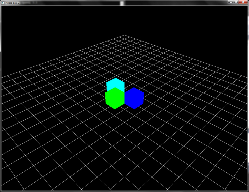
The intersectBox function works by finding the intersection of the ray with a pair of slabs for each of the three axes individually. Next it finds the tNear and tFar values. The box can only intersect with the ray if tNear is less than tFar for all of the three axes. So the code finds the smallest tFar value and the largest tMin value. If the smallest tFar value is less than the largest tNear value, the ray misses the box. For further details, refer to the See also section. The output result from the demonstration application for this recipe uses the same scene as in the last two recipes. In this case also, left-clicking the mouse selects the box, which is highlighted in cyan, as shown in the following figure:

Chapter2/Picking_SceneIntersection folder. Relevant source files are in the Chapter2/src folder.
For picking with scene intersection queries, take the following steps:
- Get two object-space points by unprojecting the screen-space point (
x, HEIGHT-y), with different depth value, one at z=0 and the other at z=1:glm::vec3 start = glm::unProject(glm::vec3(x,HEIGHT-y,0), MV, P, glm::vec4(0,0,WIDTH,HEIGHT)); glm::vec3 end = glm::unProject(glm::vec3(x,HEIGHT-y,1), MV, P, glm::vec4(0,0,WIDTH,HEIGHT));
- Get the current camera position as
eyeRay.originand geteyeRay.directionby subtracting and normalizing the difference of the two object-space points,endandstart, as follows:eyeRay.origin = cam.GetPosition(); eyeRay.direction = glm::normalize(end-start);
- For all of the objects in the scene, find the intersection of the eye ray with the Axially Aligned Bounding Box (AABB) of the object. Store the nearest intersected object index:
float tMin = numeric_limits<float>::max(); selected_box = -1; for(int i=0;i<3;i++) { glm::vec2 tMinMax = intersectBox(eyeRay, boxes[i]); if(tMinMax.x<tMinMax.y && tMinMax.x<tMin) { selected_box=i; tMin = tMinMax.x; } } if(selected_box==-1) cout<<"No box picked"<<endl; else cout<<"Selected box: "<<selected_box<<endl;
The method discussed in this recipe first casts a ray from the camera origin in the clicked direction, and then checks all of the scene objects' bounding boxes for intersection. There are two sub parts: estimation of the ray direction from the clicked point and the ray AABB intersection. We first focus on the estimation of the ray direction from the clicked point.
After calculating the eye ray, we check it for intersection with all of the scene geometries. If the object-bounding box intersects the eye ray and it is the nearest intersection, we store the index of the object. The intersectBox function is defined as follows:
The intersectBox function works by finding the intersection of the ray with a pair of slabs for each of the three axes individually. Next it finds the tNear and tFar values. The box can only intersect with the ray if tNear is less than tFar for all of the three axes. So the code finds the smallest tFar value and the largest tMin value. If the smallest tFar value is less than the largest tNear value, the ray misses the box. For further details, refer to the See also section. The output result from the demonstration application for this recipe uses the same scene as in the last two recipes. In this case also, left-clicking the mouse selects the box, which is highlighted in cyan, as shown in the following figure:
x, HEIGHT-y), with different depth value, one at z=0 and the other at z=1:glm::vec3 start = glm::unProject(glm::vec3(x,HEIGHT-y,0), MV, P, glm::vec4(0,0,WIDTH,HEIGHT)); glm::vec3 end = glm::unProject(glm::vec3(x,HEIGHT-y,1), MV, P, glm::vec4(0,0,WIDTH,HEIGHT));
eyeRay.origin and get eyeRay.direction by subtracting and normalizing the difference of the two object-space points, end and start, as follows:eyeRay.origin = cam.GetPosition(); eyeRay.direction = glm::normalize(end-start);
The method discussed in this recipe first casts a ray from the camera origin in the clicked direction, and then checks all of the scene objects' bounding boxes for intersection. There are two sub parts: estimation of the ray direction from the clicked point and the ray AABB intersection. We first focus on the estimation of the ray direction from the clicked point.
After calculating the eye ray, we check it for intersection with all of the scene geometries. If the object-bounding box intersects the eye ray and it is the nearest intersection, we store the index of the object. The intersectBox function is defined as follows:
The intersectBox function works by finding the intersection of the ray with a pair of slabs for each of the three axes individually. Next it finds the tNear and tFar values. The box can only intersect with the ray if tNear is less than tFar for all of the three axes. So the code finds the smallest tFar value and the largest tMin value. If the smallest tFar value is less than the largest tNear value, the ray misses the box. For further details, refer to the See also section. The output result from the demonstration application for this recipe uses the same scene as in the last two recipes. In this case also, left-clicking the mouse selects the box, which is highlighted in cyan, as shown in the following figure:
discussed in this recipe first casts a ray from the camera origin in the clicked direction, and then checks all of the scene objects' bounding boxes for intersection. There are two sub parts: estimation of the ray direction from the clicked point and the ray AABB intersection. We first focus on the estimation of the ray direction from the clicked point.
After calculating the eye ray, we check it for intersection with all of the scene geometries. If the object-bounding box intersects the eye ray and it is the nearest intersection, we store the index of the object. The intersectBox function is defined as follows:
The intersectBox function works by finding the intersection of the ray with a pair of slabs for each of the three axes individually. Next it finds the tNear and tFar values. The box can only intersect with the ray if tNear is less than tFar for all of the three axes. So the code finds the smallest tFar value and the largest tMin value. If the smallest tFar value is less than the largest tNear value, the ray misses the box. For further details, refer to the See also section. The output result from the demonstration application for this recipe uses the same scene as in the last two recipes. In this case also, left-clicking the mouse selects the box, which is highlighted in cyan, as shown in the following figure:
intersectBox function