

In this chapter, we will focus on:
While simple demos and applications can get along with basic primitives like cubes and spheres, most real-world applications and games use 3D mesh models which are modelled in 3D modeling software such as 3ds Max and Maya. For games, the models are then exported into the proprietary game format and then the models are loaded into the game.
While there are many formats available, some formats such as Autodesk® 3ds and Wavefront® OBJ are common formats. In this chapter, we will look at recipes for loading these model formats. We will look at how to load the geometry information, stored in the external files, into the vertex buffer object memory of the GPU. In addition, we will also load material and texture information which is required to improve the fidelity of the model so that it appears more realistic. We will also work on loading terrains which are often used to model outdoor environments. Finally, we will implement a basic particle system for simulating fuzzy phenomena such as fire and smoke. All of the discussed techniques will be implemented in the OpenGL v3.3 and above core profile.
Several demos and applications require rendering of terrains. This recipe will show how to implement terrain generation in modern OpenGL. The height map is loaded using the SOIL image loading library which contains displacement information. A 2D grid is then generated depending on the required terrain resolution. Then, the displacement information contained in the height map is used to displace the 2D grid in the vertex shader. Usually, the obtained displacement value is scaled to increase or decrease the displacement scale as desired.
For the terrain, first the 2D grid geometry is generated depending on the terrain resolution. The steps to generate such geometry were previously covered in the Doing a ripple mesh deformer using vertex shader recipe in Chapter 1, Introduction to Modern OpenGL. The code for this recipe is contained in the Chapter5/TerrainLoading directory.
Let us start our recipe by following these simple steps:
- Load the height map texture using the
SOILimage loading library and generate an OpenGL texture from it. The texture filtering is set toGL_NEARESTas we want to obtain the exact values from the height map. If we had changed this toGL_LINEAR, we would get interpolated values. Since the terrain height map is not tiled, we set the texture wrap mode toGL_CLAMP.int texture_width = 0, texture_height = 0, channels=0; GLubyte* pData = SOIL_load_image(filename.c_str(),&texture_width, &texture_height, &channels, SOIL_LOAD_L); //vertically flip the image data for( j = 0; j*2 < texture_height; ++j ) { int index1 = j * texture_width ; int index2 = (texture_height - 1 - j) * texture_width ; for( i = texture_width ; i > 0; --i ) { GLubyte temp = pData[index1]; pData[index1] = pData[index2]; pData[index2] = temp; ++index1; ++index2; } } glGenTextures(1, &heightMapTextureID); glActiveTexture(GL_TEXTURE0); glBindTexture(GL_TEXTURE_2D, heightMapTextureID); glTexParameteri(GL_TEXTURE_2D, GL_TEXTURE_MIN_FILTER, GL_NEAREST); glTexParameteri(GL_TEXTURE_2D, GL_TEXTURE_MAG_FILTER, GL_NEAREST); glTexParameteri(GL_TEXTURE_2D, GL_TEXTURE_WRAP_S, GL_CLAMP); glTexParameteri(GL_TEXTURE_2D, GL_TEXTURE_WRAP_T, GL_CLAMP); glTexImage2D(GL_TEXTURE_2D, 0, GL_RED, texture_width, texture_height, 0, GL_RED, GL_UNSIGNED_BYTE, pData); SOIL_free_image_data(pData);
- Set up the terrain geometry by generating a set of points in the XZ plane. The
TERRAIN_WIDTHparameter controls the total number of vertices in the X axis whereas theTERRAIN_DEPTHparameter controls the total number of vertices in the Z axis.for( j=0;j<TERRAIN_DEPTH;j++) { for( i=0;i<TERRAIN_WIDTH;i++) { vertices[count]=glm::vec3((float(i)/(TERRAIN_WIDTH-1)), 0, (float(j)/(TERRAIN_DEPTH-1))); count++; } } - Set up the vertex shader that displaces the 2D terrain mesh. Refer to
Chapter5/TerrainLoading/shaders/shader.vertfor details. The height value is obtained from the height map. This value is then added to the current vertex position and finally multiplied with the combined modelview projection (MVP) matrix to get the clip space position. TheHALF_TERRAIN_SIZEuniform contains half of the total number of vertices in both the X and Z axes, that is,HALF_TERRAIN_SIZE = ivec2(TERRAIN_WIDTH/2, TERRAIN_DEPTH/2). Similarly the scale uniform is used to scale the height read from the height map. Thehalf_scaleandHALF_TERRAIN_SIZEuniforms are used to position the mesh at origin.#version 330 core layout (location=0) in vec3 vVertex; uniform mat4 MVP; uniform ivec2 HALF_TERRAIN_SIZE; uniform sampler2D heightMapTexture; uniform float scale; uniform float half_scale; void main() { float height = texture(heightMapTexture, vVertex.xz).r*scale - half_scale; vec2 pos = (vVertex.xz*2.0-1)*HALF_TERRAIN_SIZE; gl_Position = MVP*vec4(pos.x, height, pos.y, 1); } - Load the shaders and the corresponding uniform and attribute locations. Also, set the values of the uniforms that never change during the lifetime of the application, at initialization.
shader.LoadFromFile(GL_VERTEX_SHADER, "shaders/shader.vert"); shader.LoadFromFile(GL_FRAGMENT_SHADER, "shaders/shader.frag"); shader.CreateAndLinkProgram(); shader.Use(); shader.AddAttribute("vVertex"); shader.AddUniform("heightMapTexture"); shader.AddUniform("scale"); shader.AddUniform("half_scale"); shader.AddUniform("HALF_TERRAIN_SIZE"); shader.AddUniform("MVP"); glUniform1i(shader("heightMapTexture"), 0); glUniform2i(shader("HALF_TERRAIN_SIZE"), TERRAIN_WIDTH>>1, TERRAIN_DEPTH>>1); glUniform1f(shader("scale"), scale); glUniform1f(shader("half_scale"), half_scale); shader.UnUse(); - In the rendering code, set the shader and render the terrain by passing the modelview/projection matrices to the shader as shader uniforms.
shader.Use(); glUniformMatrix4fv(shader("MVP"), 1, GL_FALSE, glm::value_ptr(MVP)); glDrawElements(GL_TRIANGLES,TOTAL_INDICES, GL_UNSIGNED_INT, 0); shader.UnUse();
Terrain rendering is relatively straight forward to implement. The geometry is first generated on the CPU and is then stored in the GPU buffer objects. Next, the height map is loaded from an image which is then transferred to the vertex shader as a texture sampler uniform.
The output from the demo application for this recipe renders a wireframe terrain as shown in the following screenshot:
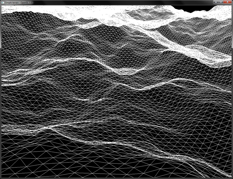
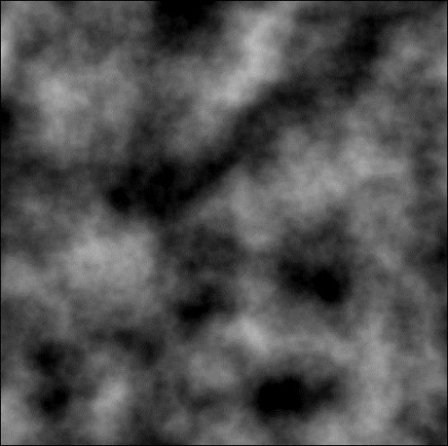
The height map used to generate this terrain is shown in the following screenshot:
The method we have presented in this recipe uses the vertex displacement to generate a terrain from a height map. There are several tools available that can help with the terrain height map generation. One of them is Terragen (planetside.co.uk). Another useful tool is World Machine (http://world-machine.com/). A general source of information for terrains is available at the virtual terrain project (http://vterrain.org/).
We can also use procedural methods to generate terrains such as fractal terrain generation. Noise methods can also be helpful in the generation of the terrains.
To know more about implementing terrains, you can check the following:
- Focus on 3D Terrain Programming, by Trent Polack, Premier Press, 2002
- Chapter 7, Terrain Level of Detail in Level of Detail for 3D Graphics by David Luebke, Morgan Kaufmann Publishers, 2003.
Chapter 1, Introduction to Modern OpenGL. The code for this recipe is contained in the Chapter5/TerrainLoading directory.
Let us start our recipe by following these simple steps:
- Load the height map texture using the
SOILimage loading library and generate an OpenGL texture from it. The texture filtering is set toGL_NEARESTas we want to obtain the exact values from the height map. If we had changed this toGL_LINEAR, we would get interpolated values. Since the terrain height map is not tiled, we set the texture wrap mode toGL_CLAMP.int texture_width = 0, texture_height = 0, channels=0; GLubyte* pData = SOIL_load_image(filename.c_str(),&texture_width, &texture_height, &channels, SOIL_LOAD_L); //vertically flip the image data for( j = 0; j*2 < texture_height; ++j ) { int index1 = j * texture_width ; int index2 = (texture_height - 1 - j) * texture_width ; for( i = texture_width ; i > 0; --i ) { GLubyte temp = pData[index1]; pData[index1] = pData[index2]; pData[index2] = temp; ++index1; ++index2; } } glGenTextures(1, &heightMapTextureID); glActiveTexture(GL_TEXTURE0); glBindTexture(GL_TEXTURE_2D, heightMapTextureID); glTexParameteri(GL_TEXTURE_2D, GL_TEXTURE_MIN_FILTER, GL_NEAREST); glTexParameteri(GL_TEXTURE_2D, GL_TEXTURE_MAG_FILTER, GL_NEAREST); glTexParameteri(GL_TEXTURE_2D, GL_TEXTURE_WRAP_S, GL_CLAMP); glTexParameteri(GL_TEXTURE_2D, GL_TEXTURE_WRAP_T, GL_CLAMP); glTexImage2D(GL_TEXTURE_2D, 0, GL_RED, texture_width, texture_height, 0, GL_RED, GL_UNSIGNED_BYTE, pData); SOIL_free_image_data(pData);
- Set up the terrain geometry by generating a set of points in the XZ plane. The
TERRAIN_WIDTHparameter controls the total number of vertices in the X axis whereas theTERRAIN_DEPTHparameter controls the total number of vertices in the Z axis.for( j=0;j<TERRAIN_DEPTH;j++) { for( i=0;i<TERRAIN_WIDTH;i++) { vertices[count]=glm::vec3((float(i)/(TERRAIN_WIDTH-1)), 0, (float(j)/(TERRAIN_DEPTH-1))); count++; } } - Set up the vertex shader that displaces the 2D terrain mesh. Refer to
Chapter5/TerrainLoading/shaders/shader.vertfor details. The height value is obtained from the height map. This value is then added to the current vertex position and finally multiplied with the combined modelview projection (MVP) matrix to get the clip space position. TheHALF_TERRAIN_SIZEuniform contains half of the total number of vertices in both the X and Z axes, that is,HALF_TERRAIN_SIZE = ivec2(TERRAIN_WIDTH/2, TERRAIN_DEPTH/2). Similarly the scale uniform is used to scale the height read from the height map. Thehalf_scaleandHALF_TERRAIN_SIZEuniforms are used to position the mesh at origin.#version 330 core layout (location=0) in vec3 vVertex; uniform mat4 MVP; uniform ivec2 HALF_TERRAIN_SIZE; uniform sampler2D heightMapTexture; uniform float scale; uniform float half_scale; void main() { float height = texture(heightMapTexture, vVertex.xz).r*scale - half_scale; vec2 pos = (vVertex.xz*2.0-1)*HALF_TERRAIN_SIZE; gl_Position = MVP*vec4(pos.x, height, pos.y, 1); } - Load the shaders and the corresponding uniform and attribute locations. Also, set the values of the uniforms that never change during the lifetime of the application, at initialization.
shader.LoadFromFile(GL_VERTEX_SHADER, "shaders/shader.vert"); shader.LoadFromFile(GL_FRAGMENT_SHADER, "shaders/shader.frag"); shader.CreateAndLinkProgram(); shader.Use(); shader.AddAttribute("vVertex"); shader.AddUniform("heightMapTexture"); shader.AddUniform("scale"); shader.AddUniform("half_scale"); shader.AddUniform("HALF_TERRAIN_SIZE"); shader.AddUniform("MVP"); glUniform1i(shader("heightMapTexture"), 0); glUniform2i(shader("HALF_TERRAIN_SIZE"), TERRAIN_WIDTH>>1, TERRAIN_DEPTH>>1); glUniform1f(shader("scale"), scale); glUniform1f(shader("half_scale"), half_scale); shader.UnUse(); - In the rendering code, set the shader and render the terrain by passing the modelview/projection matrices to the shader as shader uniforms.
shader.Use(); glUniformMatrix4fv(shader("MVP"), 1, GL_FALSE, glm::value_ptr(MVP)); glDrawElements(GL_TRIANGLES,TOTAL_INDICES, GL_UNSIGNED_INT, 0); shader.UnUse();
Terrain rendering is relatively straight forward to implement. The geometry is first generated on the CPU and is then stored in the GPU buffer objects. Next, the height map is loaded from an image which is then transferred to the vertex shader as a texture sampler uniform.
The output from the demo application for this recipe renders a wireframe terrain as shown in the following screenshot:
The height map used to generate this terrain is shown in the following screenshot:
The method we have presented in this recipe uses the vertex displacement to generate a terrain from a height map. There are several tools available that can help with the terrain height map generation. One of them is Terragen (planetside.co.uk). Another useful tool is World Machine (http://world-machine.com/). A general source of information for terrains is available at the virtual terrain project (http://vterrain.org/).
We can also use procedural methods to generate terrains such as fractal terrain generation. Noise methods can also be helpful in the generation of the terrains.
To know more about implementing terrains, you can check the following:
- Focus on 3D Terrain Programming, by Trent Polack, Premier Press, 2002
- Chapter 7, Terrain Level of Detail in Level of Detail for 3D Graphics by David Luebke, Morgan Kaufmann Publishers, 2003.
SOIL image loading library and generate an OpenGL texture from it. The texture filtering is set to GL_NEAREST as we want to obtain the exact values from the height map. If we had changed this to GL_LINEAR, we would get interpolated values. Since the terrain height map is not tiled, we set the texture wrap mode to GL_CLAMP.int texture_width = 0, texture_height = 0, channels=0; GLubyte* pData = SOIL_load_image(filename.c_str(),&texture_width, &texture_height, &channels, SOIL_LOAD_L); //vertically flip the image data for( j = 0; j*2 < texture_height; ++j ) { int index1 = j * texture_width ; int index2 = (texture_height - 1 - j) * texture_width ; for( i = texture_width ; i > 0; --i ) { GLubyte temp = pData[index1]; pData[index1] = pData[index2]; pData[index2] = temp; ++index1; ++index2; } } glGenTextures(1, &heightMapTextureID); glActiveTexture(GL_TEXTURE0); glBindTexture(GL_TEXTURE_2D, heightMapTextureID); glTexParameteri(GL_TEXTURE_2D, GL_TEXTURE_MIN_FILTER, GL_NEAREST); glTexParameteri(GL_TEXTURE_2D, GL_TEXTURE_MAG_FILTER, GL_NEAREST); glTexParameteri(GL_TEXTURE_2D, GL_TEXTURE_WRAP_S, GL_CLAMP); glTexParameteri(GL_TEXTURE_2D, GL_TEXTURE_WRAP_T, GL_CLAMP); glTexImage2D(GL_TEXTURE_2D, 0, GL_RED, texture_width, texture_height, 0, GL_RED, GL_UNSIGNED_BYTE, pData); SOIL_free_image_data(pData);
TERRAIN_WIDTH parameter
- controls the total number of vertices in the X axis whereas the
TERRAIN_DEPTHparameter controls the total number of vertices in the Z axis.for( j=0;j<TERRAIN_DEPTH;j++) { for( i=0;i<TERRAIN_WIDTH;i++) { vertices[count]=glm::vec3((float(i)/(TERRAIN_WIDTH-1)), 0, (float(j)/(TERRAIN_DEPTH-1))); count++; } } - Set up the vertex shader that displaces the 2D terrain mesh. Refer to
Chapter5/TerrainLoading/shaders/shader.vertfor details. The height value is obtained from the height map. This value is then added to the current vertex position and finally multiplied with the combined modelview projection (MVP) matrix to get the clip space position. TheHALF_TERRAIN_SIZEuniform contains half of the total number of vertices in both the X and Z axes, that is,HALF_TERRAIN_SIZE = ivec2(TERRAIN_WIDTH/2, TERRAIN_DEPTH/2). Similarly the scale uniform is used to scale the height read from the height map. Thehalf_scaleandHALF_TERRAIN_SIZEuniforms are used to position the mesh at origin.#version 330 core layout (location=0) in vec3 vVertex; uniform mat4 MVP; uniform ivec2 HALF_TERRAIN_SIZE; uniform sampler2D heightMapTexture; uniform float scale; uniform float half_scale; void main() { float height = texture(heightMapTexture, vVertex.xz).r*scale - half_scale; vec2 pos = (vVertex.xz*2.0-1)*HALF_TERRAIN_SIZE; gl_Position = MVP*vec4(pos.x, height, pos.y, 1); } - Load the shaders and the corresponding uniform and attribute locations. Also, set the values of the uniforms that never change during the lifetime of the application, at initialization.
shader.LoadFromFile(GL_VERTEX_SHADER, "shaders/shader.vert"); shader.LoadFromFile(GL_FRAGMENT_SHADER, "shaders/shader.frag"); shader.CreateAndLinkProgram(); shader.Use(); shader.AddAttribute("vVertex"); shader.AddUniform("heightMapTexture"); shader.AddUniform("scale"); shader.AddUniform("half_scale"); shader.AddUniform("HALF_TERRAIN_SIZE"); shader.AddUniform("MVP"); glUniform1i(shader("heightMapTexture"), 0); glUniform2i(shader("HALF_TERRAIN_SIZE"), TERRAIN_WIDTH>>1, TERRAIN_DEPTH>>1); glUniform1f(shader("scale"), scale); glUniform1f(shader("half_scale"), half_scale); shader.UnUse(); - In the rendering code, set the shader and render the terrain by passing the modelview/projection matrices to the shader as shader uniforms.
shader.Use(); glUniformMatrix4fv(shader("MVP"), 1, GL_FALSE, glm::value_ptr(MVP)); glDrawElements(GL_TRIANGLES,TOTAL_INDICES, GL_UNSIGNED_INT, 0); shader.UnUse();
Terrain rendering is relatively straight forward to implement. The geometry is first generated on the CPU and is then stored in the GPU buffer objects. Next, the height map is loaded from an image which is then transferred to the vertex shader as a texture sampler uniform.
The output from the demo application for this recipe renders a wireframe terrain as shown in the following screenshot:
The height map used to generate this terrain is shown in the following screenshot:
The method we have presented in this recipe uses the vertex displacement to generate a terrain from a height map. There are several tools available that can help with the terrain height map generation. One of them is Terragen (planetside.co.uk). Another useful tool is World Machine (http://world-machine.com/). A general source of information for terrains is available at the virtual terrain project (http://vterrain.org/).
We can also use procedural methods to generate terrains such as fractal terrain generation. Noise methods can also be helpful in the generation of the terrains.
To know more about implementing terrains, you can check the following:
- Focus on 3D Terrain Programming, by Trent Polack, Premier Press, 2002
- Chapter 7, Terrain Level of Detail in Level of Detail for 3D Graphics by David Luebke, Morgan Kaufmann Publishers, 2003.
terrain height map generation. One of them is Terragen (planetside.co.uk). Another useful tool is World Machine (http://world-machine.com/). A general source of information for terrains is available at the virtual terrain project (http://vterrain.org/).
We can also use procedural methods to generate terrains such as fractal terrain generation. Noise methods can also be helpful in the generation of the terrains.
To know more about implementing terrains, you can check the following:
- Focus on 3D Terrain Programming, by Trent Polack, Premier Press, 2002
- Chapter 7, Terrain Level of Detail in Level of Detail for 3D Graphics by David Luebke, Morgan Kaufmann Publishers, 2003.
- Chapter 7, Terrain Level of Detail in Level of Detail for 3D Graphics by David Luebke, Morgan Kaufmann Publishers, 2003.
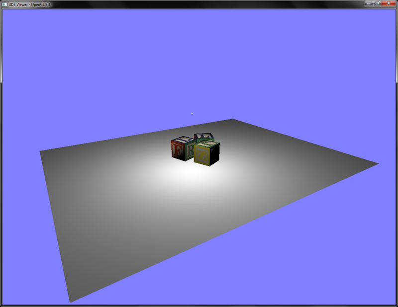
We will now create model loader and renderer for Autodesk® 3ds model format which is a simple yet efficient binary model format for storing digital assets.
The code for this recipe is contained in the Chapter5/3DsViewer folder. This recipe will be using the Drawing a 2D image in a window using a fragment shader and the SOIL image loading library recipe from Chapter 1, Introduction to Modern OpenGL, for loading the 3ds mesh file's textures using the SOIL image loading library.
The steps required to implement a 3ds file viewer are as follows:
- Create an instance of the
C3dsLoaderclass. Then call theC3dsLoader::Load3DSfunction passing it the name of the mesh file and a set of vectors to store the submeshes, vertices, normals, uvs, indices, and materials.if(!loader.Load3DS(mesh_filename.c_str( ), meshes, vertices, normals, uvs, faces, indices, materials)) { cout<<"Cannot load the 3ds mesh"<<endl; exit(EXIT_FAILURE); } - After the mesh is loaded, use the mesh's material list to load the material textures into the OpenGL texture object.
for(size_t k=0;k<materials.size();k++) { for(size_t m=0;m< materials[k]->textureMaps.size();m++) { GLuint id = 0; glGenTextures(1, &id); glBindTexture(GL_TEXTURE_2D, id); glTexParameteri(GL_TEXTURE_2D, GL_TEXTURE_MIN_FILTER, GL_LINEAR); glTexParameteri(GL_TEXTURE_2D, GL_TEXTURE_MAG_FILTER, GL_LINEAR); glTexParameteri(GL_TEXTURE_2D, GL_TEXTURE_WRAP_S, GL_REPEAT); glTexParameteri(GL_TEXTURE_2D, GL_TEXTURE_WRAP_T, GL_REPEAT); int texture_width = 0, texture_height = 0, channels=0; const string& filename = materials[k]->textureMaps[m]->filename; std::string full_filename = mesh_path; full_filename.append(filename); GLubyte* pData = SOIL_load_image(full_filename.c_str(), &texture_width, &texture_height, &channels, SOIL_LOAD_AUTO); if(pData == NULL) { cerr<<"Cannot load image: "<<full_filename.c_str()<<endl; exit(EXIT_FAILURE); } //Flip the image on Y axis int i,j; for( j = 0; j*2 < texture_height; ++j ) { int index1 = j * texture_width * channels; int index2 = (texture_height - 1 - j) * texture_width * channels; for( i = texture_width * channels; i > 0; --i ){ GLubyte temp = pData[index1]; pData[index1] = pData[index2]; pData[index2] = temp; ++index1; ++index2; } } GLenum format = GL_RGBA; switch(channels) { case 2: format = GL_RG32UI; break; case 3: format = GL_RGB; break; case 4: format = GL_RGBA; break; } glTexImage2D(GL_TEXTURE_2D, 0, format, texture_width, texture_height, 0, format, GL_UNSIGNED_BYTE, pData); SOIL_free_image_data(pData); textureMaps[filename]=id; } } - Pass the loaded per-vertex attributes; that is, positions (
vertices), texture coordinates (uvs), per-vertex normals (normals), and triangle indices (indices) to GPU memory by allocating separate buffer objects for each attribute. Note that for easier handling of buffer objects, we bind a single vertex array object (vaoID) first.glBindVertexArray(vaoID); glBindBuffer (GL_ARRAY_BUFFER, vboVerticesID); glBufferData (GL_ARRAY_BUFFER, sizeof(glm::vec3)* vertices.size(), &(vertices[0].x), GL_STATIC_DRAW); glEnableVertexAttribArray(shader["vVertex"]); glVertexAttribPointer(shader["vVertex"], 3, GL_FLOAT, GL_FALSE,0,0); glBindBuffer (GL_ARRAY_BUFFER, vboUVsID); glBufferData (GL_ARRAY_BUFFER, sizeof(glm::vec2)*uvs.size(), &(uvs[0].x), GL_STATIC_DRAW); glEnableVertexAttribArray(shader["vUV"]); glVertexAttribPointer(shader["vUV"],2,GL_FLOAT,GL_FALSE,0, 0); glBindBuffer (GL_ARRAY_BUFFER, vboNormalsID); glBufferData (GL_ARRAY_BUFFER, sizeof(glm::vec3)* normals.size(), &(normals[0].x), GL_STATIC_DRAW); glEnableVertexAttribArray(shader["vNormal"]); glVertexAttribPointer(shader["vNormal"], 3, GL_FLOAT, GL_FALSE, 0, 0);
- If we have only a single material in the 3ds file, we store the face indices into
GL_ELEMENT_ARRAY_BUFFERso that we can render the whole mesh in a single call. However, if we have more than one material, we bind the appropriate submeshes separately. TheglBufferDatacall allocates the GPU memory, however, it is not initialized. In order to initialize the buffer object memory, we can use theglMapBufferfunction to obtain a direct pointer to the GPU memory. Using this pointer, we can then write to the GPU memory. An alternative to usingglMapBufferisglBufferSubDatawhich can modify the GPU memory by copying contents from a CPU buffer.if(materials.size()==1) { glBindBuffer(GL_ELEMENT_ARRAY_BUFFER, vboIndicesID); glBufferData(GL_ELEMENT_ARRAY_BUFFER, sizeof(GLushort)* 3*faces.size(), 0, GL_STATIC_DRAW); GLushort* pIndices = static_cast<GLushort*>(glMapBuffer(GL_ELEMENT_ARRAY_BUFFER, GL_WRITE_ONLY)); for(size_t i=0;i<faces.size();i++) { *(pIndices++)=faces[i].a; *(pIndices++)=faces[i].b; *(pIndices++)=faces[i].c; } glUnmapBuffer(GL_ELEMENT_ARRAY_BUFFER); } - Set up the vertex shader to output the clip space position as well as the per-vertex texture coordinates. The texture coordinates are then interpolated by the rasterizer to the fragment shader using an output attribute
vUVout.#version 330 core layout(location = 0) in vec3 vVertex; layout(location = 1) in vec3 vNormal; layout(location = 2) in vec2 vUV; smooth out vec2 vUVout; uniform mat4 P; uniform mat4 MV; uniform mat3 N; smooth out vec3 vEyeSpaceNormal; smooth out vec3 vEyeSpacePosition; void main() { vUVout=vUV; vEyeSpacePosition = (MV*vec4(vVertex,1)).xyz; vEyeSpaceNormal = N*vNormal; gl_Position = P*vec4(vEyeSpacePosition,1); }
- Set up the fragment shader, which looks up the texture map sampler with the interpolated texture coordinates from the rasterizer. Depending on whether the submesh has a texture, we linearly interpolate between the texture map color and the diffused color of the material, using the GLSL mix function.
#version 330 core uniform sampler2D textureMap; uniform float hasTexture; uniform vec3 light_position;//light position in object space uniform mat4 MV; smooth in vec3 vEyeSpaceNormal; smooth in vec3 vEyeSpacePosition; smooth in vec2 vUVout; layout(location=0) out vec4 vFragColor; const float k0 = 1.0;//constant attenuation const float k1 = 0.0;//linear attenuation const float k2 = 0.0;//quadratic attenuation void main() { vec4 vEyeSpaceLightPosition = (MV*vec4(light_position,1)); vec3 L = (vEyeSpaceLightPosition.xyz-vEyeSpacePosition); float d = length(L); L = normalize(L); float diffuse = max(0, dot(vEyeSpaceNormal, L)); float attenuationAmount = 1.0/(k0 + (k1*d) + (k2*d*d)); diffuse *= attenuationAmount; vFragColor = diffuse*mix(vec4(1),texture(textureMap, vUVout), hasTexture); }
- The rendering code binds the shader program, sets the shader uniforms, and then renders the mesh, depending on how many materials the 3ds mesh has. If the mesh has only a single material, it is drawn in a single call to
glDrawElementby using the indices attached to theGL_ELEMENT_ARRAY_BUFFERbinding point.glBindVertexArray(vaoID); { shader.Use(); glUniformMatrix4fv(shader("MV"), 1, GL_FALSE, glm::value_ptr(MV)); glUniformMatrix3fv(shader("N"), 1, GL_FALSE, glm::value_ptr(glm::inverseTranspose(glm::mat3(MV)))); glUniformMatrix4fv(shader("P"), 1, GL_FALSE, glm::value_ptr(P)); glUniform3fv(shader("light_position"),1, &(lightPosOS.x)); if(materials.size()==1) { GLint whichID[1]; glGetIntegerv(GL_TEXTURE_BINDING_2D, whichID); if(textureMaps.size()>0) { if(whichID[0] != textureMaps[materials[0]->textureMaps[0]->filename]) { glBindTexture(GL_TEXTURE_2D, textureMaps[materials[0]->textureMaps[0]->filename]); glUniform1f(shader("hasTexture"),1.0); } } else { glUniform1f(shader("hasTexture"),0.0); glUniform3fv(shader("diffuse_color"),1, materials[0]->diffuse); } glDrawElements(GL_TRIANGLES, meshes[0]->faces.size()*3, GL_UNSIGNED_SHORT, 0); } - If the mesh contains more than one material, we iterate through the material list, and bind the texture map (if the material has one), otherwise we use the diffuse color stored in the material for the submesh. Finally, we pass the
sub_indicesarray stored in the material to theglDrawElementsfunction to load those indices only.else { for(size_t i=0;i<materials.size();i++) { GLint whichID[1]; glGetIntegerv(GL_TEXTURE_BINDING_2D, whichID); if(materials[i]->textureMaps.size()>0) { if(whichID[0] != textureMaps[materials[i]->textureMaps[0]->filename]) { glBindTexture(GL_TEXTURE_2D, textureMaps[materials[i]->textureMaps[0]->filename]); } glUniform1f(shader("hasTexture"),1.0); } else { glUniform1f(shader("hasTexture"),0.0); } glUniform3fv(shader("diffuse_color"),1, materials[i]->diffuse); glDrawElements(GL_TRIANGLES, materials[i]->sub_indices.size(), GL_UNSIGNED_SHORT, &(materials[i]->sub_indices[0])); } } shader.UnUse();
The main component of this recipe is the C3dsLoader::Load3DS function. The 3ds file is a binary file which is organized into a collection of chunks. Typically, a reader reads the first two bytes from the file which are stored in the chunk ID. The next four bytes store the chunk length in bytes. We continue reading chunks, and their lengths, and then store data appropriately into our vectors/variables until there are no more chunks and we pass reading the end of file. The 3ds specifications detail all of the chunks and their lengths as well as subchunks, as shown in the following figure:

Note that if there is a subchunk that we are interested in, we need to read the parent chunk as well, to move the file pointer to the appropriate offset in the file, for our required chunk. The loader first finds the total size of the 3ds mesh file in bytes. Then, it runs a while loop that checks to see if the current file pointer is within the file's size. If it is, it continues to read the first two bytes (the chunk's ID) and the next four bytes (the chunk's length).
All names (object name, material name, or texture map name) have to be read byte-by-byte until the null terminator character (\0) is found. For reading vertices, we first read two bytes that store the total number of vertices (N). Two bytes means that the maximum number of vertices one mesh can store is 65536. Then, we read the whole chunk of bytes, that is, sizeof(glm::vec3)*N, directly into our mesh's vertices, shown as follows:
Note that the 3ds format does not store the per-vertex normal explicitly. It only stores smoothing groups which tell us which faces have shared normals. After we have the vertex positions and face information, we can generate the per-vertex normals by averaging the per-face normals. This is carried out by using the following code snippet in the 3ds.cpp file. We first allocate space for the per-vertex normals. Then we estimate the face's normal by using the cross product of the two edges. Finally, we add the face normal to the appropriate vertex index and then normalize the normal.
Once we have all the per-vertex attributes and faces information, we use this to group the triangles by material. We loop through all of the materials and expand their face IDs to include the three vertex IDs and make the face.
Chapter5/3DsViewer folder. This recipe will be using the Drawing a 2D image in a window using a fragment shader and the SOIL image loading library recipe from
Chapter 1, Introduction to Modern OpenGL, for loading the 3ds mesh file's textures using the SOIL image loading library.
The steps required to implement a 3ds file viewer are as follows:
- Create an instance of the
C3dsLoaderclass. Then call theC3dsLoader::Load3DSfunction passing it the name of the mesh file and a set of vectors to store the submeshes, vertices, normals, uvs, indices, and materials.if(!loader.Load3DS(mesh_filename.c_str( ), meshes, vertices, normals, uvs, faces, indices, materials)) { cout<<"Cannot load the 3ds mesh"<<endl; exit(EXIT_FAILURE); } - After the mesh is loaded, use the mesh's material list to load the material textures into the OpenGL texture object.
for(size_t k=0;k<materials.size();k++) { for(size_t m=0;m< materials[k]->textureMaps.size();m++) { GLuint id = 0; glGenTextures(1, &id); glBindTexture(GL_TEXTURE_2D, id); glTexParameteri(GL_TEXTURE_2D, GL_TEXTURE_MIN_FILTER, GL_LINEAR); glTexParameteri(GL_TEXTURE_2D, GL_TEXTURE_MAG_FILTER, GL_LINEAR); glTexParameteri(GL_TEXTURE_2D, GL_TEXTURE_WRAP_S, GL_REPEAT); glTexParameteri(GL_TEXTURE_2D, GL_TEXTURE_WRAP_T, GL_REPEAT); int texture_width = 0, texture_height = 0, channels=0; const string& filename = materials[k]->textureMaps[m]->filename; std::string full_filename = mesh_path; full_filename.append(filename); GLubyte* pData = SOIL_load_image(full_filename.c_str(), &texture_width, &texture_height, &channels, SOIL_LOAD_AUTO); if(pData == NULL) { cerr<<"Cannot load image: "<<full_filename.c_str()<<endl; exit(EXIT_FAILURE); } //Flip the image on Y axis int i,j; for( j = 0; j*2 < texture_height; ++j ) { int index1 = j * texture_width * channels; int index2 = (texture_height - 1 - j) * texture_width * channels; for( i = texture_width * channels; i > 0; --i ){ GLubyte temp = pData[index1]; pData[index1] = pData[index2]; pData[index2] = temp; ++index1; ++index2; } } GLenum format = GL_RGBA; switch(channels) { case 2: format = GL_RG32UI; break; case 3: format = GL_RGB; break; case 4: format = GL_RGBA; break; } glTexImage2D(GL_TEXTURE_2D, 0, format, texture_width, texture_height, 0, format, GL_UNSIGNED_BYTE, pData); SOIL_free_image_data(pData); textureMaps[filename]=id; } } - Pass the loaded per-vertex attributes; that is, positions (
vertices), texture coordinates (uvs), per-vertex normals (normals), and triangle indices (indices) to GPU memory by allocating separate buffer objects for each attribute. Note that for easier handling of buffer objects, we bind a single vertex array object (vaoID) first.glBindVertexArray(vaoID); glBindBuffer (GL_ARRAY_BUFFER, vboVerticesID); glBufferData (GL_ARRAY_BUFFER, sizeof(glm::vec3)* vertices.size(), &(vertices[0].x), GL_STATIC_DRAW); glEnableVertexAttribArray(shader["vVertex"]); glVertexAttribPointer(shader["vVertex"], 3, GL_FLOAT, GL_FALSE,0,0); glBindBuffer (GL_ARRAY_BUFFER, vboUVsID); glBufferData (GL_ARRAY_BUFFER, sizeof(glm::vec2)*uvs.size(), &(uvs[0].x), GL_STATIC_DRAW); glEnableVertexAttribArray(shader["vUV"]); glVertexAttribPointer(shader["vUV"],2,GL_FLOAT,GL_FALSE,0, 0); glBindBuffer (GL_ARRAY_BUFFER, vboNormalsID); glBufferData (GL_ARRAY_BUFFER, sizeof(glm::vec3)* normals.size(), &(normals[0].x), GL_STATIC_DRAW); glEnableVertexAttribArray(shader["vNormal"]); glVertexAttribPointer(shader["vNormal"], 3, GL_FLOAT, GL_FALSE, 0, 0);
- If we have only a single material in the 3ds file, we store the face indices into
GL_ELEMENT_ARRAY_BUFFERso that we can render the whole mesh in a single call. However, if we have more than one material, we bind the appropriate submeshes separately. TheglBufferDatacall allocates the GPU memory, however, it is not initialized. In order to initialize the buffer object memory, we can use theglMapBufferfunction to obtain a direct pointer to the GPU memory. Using this pointer, we can then write to the GPU memory. An alternative to usingglMapBufferisglBufferSubDatawhich can modify the GPU memory by copying contents from a CPU buffer.if(materials.size()==1) { glBindBuffer(GL_ELEMENT_ARRAY_BUFFER, vboIndicesID); glBufferData(GL_ELEMENT_ARRAY_BUFFER, sizeof(GLushort)* 3*faces.size(), 0, GL_STATIC_DRAW); GLushort* pIndices = static_cast<GLushort*>(glMapBuffer(GL_ELEMENT_ARRAY_BUFFER, GL_WRITE_ONLY)); for(size_t i=0;i<faces.size();i++) { *(pIndices++)=faces[i].a; *(pIndices++)=faces[i].b; *(pIndices++)=faces[i].c; } glUnmapBuffer(GL_ELEMENT_ARRAY_BUFFER); } - Set up the vertex shader to output the clip space position as well as the per-vertex texture coordinates. The texture coordinates are then interpolated by the rasterizer to the fragment shader using an output attribute
vUVout.#version 330 core layout(location = 0) in vec3 vVertex; layout(location = 1) in vec3 vNormal; layout(location = 2) in vec2 vUV; smooth out vec2 vUVout; uniform mat4 P; uniform mat4 MV; uniform mat3 N; smooth out vec3 vEyeSpaceNormal; smooth out vec3 vEyeSpacePosition; void main() { vUVout=vUV; vEyeSpacePosition = (MV*vec4(vVertex,1)).xyz; vEyeSpaceNormal = N*vNormal; gl_Position = P*vec4(vEyeSpacePosition,1); }
- Set up the fragment shader, which looks up the texture map sampler with the interpolated texture coordinates from the rasterizer. Depending on whether the submesh has a texture, we linearly interpolate between the texture map color and the diffused color of the material, using the GLSL mix function.
#version 330 core uniform sampler2D textureMap; uniform float hasTexture; uniform vec3 light_position;//light position in object space uniform mat4 MV; smooth in vec3 vEyeSpaceNormal; smooth in vec3 vEyeSpacePosition; smooth in vec2 vUVout; layout(location=0) out vec4 vFragColor; const float k0 = 1.0;//constant attenuation const float k1 = 0.0;//linear attenuation const float k2 = 0.0;//quadratic attenuation void main() { vec4 vEyeSpaceLightPosition = (MV*vec4(light_position,1)); vec3 L = (vEyeSpaceLightPosition.xyz-vEyeSpacePosition); float d = length(L); L = normalize(L); float diffuse = max(0, dot(vEyeSpaceNormal, L)); float attenuationAmount = 1.0/(k0 + (k1*d) + (k2*d*d)); diffuse *= attenuationAmount; vFragColor = diffuse*mix(vec4(1),texture(textureMap, vUVout), hasTexture); }
- The rendering code binds the shader program, sets the shader uniforms, and then renders the mesh, depending on how many materials the 3ds mesh has. If the mesh has only a single material, it is drawn in a single call to
glDrawElementby using the indices attached to theGL_ELEMENT_ARRAY_BUFFERbinding point.glBindVertexArray(vaoID); { shader.Use(); glUniformMatrix4fv(shader("MV"), 1, GL_FALSE, glm::value_ptr(MV)); glUniformMatrix3fv(shader("N"), 1, GL_FALSE, glm::value_ptr(glm::inverseTranspose(glm::mat3(MV)))); glUniformMatrix4fv(shader("P"), 1, GL_FALSE, glm::value_ptr(P)); glUniform3fv(shader("light_position"),1, &(lightPosOS.x)); if(materials.size()==1) { GLint whichID[1]; glGetIntegerv(GL_TEXTURE_BINDING_2D, whichID); if(textureMaps.size()>0) { if(whichID[0] != textureMaps[materials[0]->textureMaps[0]->filename]) { glBindTexture(GL_TEXTURE_2D, textureMaps[materials[0]->textureMaps[0]->filename]); glUniform1f(shader("hasTexture"),1.0); } } else { glUniform1f(shader("hasTexture"),0.0); glUniform3fv(shader("diffuse_color"),1, materials[0]->diffuse); } glDrawElements(GL_TRIANGLES, meshes[0]->faces.size()*3, GL_UNSIGNED_SHORT, 0); } - If the mesh contains more than one material, we iterate through the material list, and bind the texture map (if the material has one), otherwise we use the diffuse color stored in the material for the submesh. Finally, we pass the
sub_indicesarray stored in the material to theglDrawElementsfunction to load those indices only.else { for(size_t i=0;i<materials.size();i++) { GLint whichID[1]; glGetIntegerv(GL_TEXTURE_BINDING_2D, whichID); if(materials[i]->textureMaps.size()>0) { if(whichID[0] != textureMaps[materials[i]->textureMaps[0]->filename]) { glBindTexture(GL_TEXTURE_2D, textureMaps[materials[i]->textureMaps[0]->filename]); } glUniform1f(shader("hasTexture"),1.0); } else { glUniform1f(shader("hasTexture"),0.0); } glUniform3fv(shader("diffuse_color"),1, materials[i]->diffuse); glDrawElements(GL_TRIANGLES, materials[i]->sub_indices.size(), GL_UNSIGNED_SHORT, &(materials[i]->sub_indices[0])); } } shader.UnUse();
The main component of this recipe is the C3dsLoader::Load3DS function. The 3ds file is a binary file which is organized into a collection of chunks. Typically, a reader reads the first two bytes from the file which are stored in the chunk ID. The next four bytes store the chunk length in bytes. We continue reading chunks, and their lengths, and then store data appropriately into our vectors/variables until there are no more chunks and we pass reading the end of file. The 3ds specifications detail all of the chunks and their lengths as well as subchunks, as shown in the following figure:
Note that if there is a subchunk that we are interested in, we need to read the parent chunk as well, to move the file pointer to the appropriate offset in the file, for our required chunk. The loader first finds the total size of the 3ds mesh file in bytes. Then, it runs a while loop that checks to see if the current file pointer is within the file's size. If it is, it continues to read the first two bytes (the chunk's ID) and the next four bytes (the chunk's length).
All names (object name, material name, or texture map name) have to be read byte-by-byte until the null terminator character (\0) is found. For reading vertices, we first read two bytes that store the total number of vertices (N). Two bytes means that the maximum number of vertices one mesh can store is 65536. Then, we read the whole chunk of bytes, that is, sizeof(glm::vec3)*N, directly into our mesh's vertices, shown as follows:
Note that the 3ds format does not store the per-vertex normal explicitly. It only stores smoothing groups which tell us which faces have shared normals. After we have the vertex positions and face information, we can generate the per-vertex normals by averaging the per-face normals. This is carried out by using the following code snippet in the 3ds.cpp file. We first allocate space for the per-vertex normals. Then we estimate the face's normal by using the cross product of the two edges. Finally, we add the face normal to the appropriate vertex index and then normalize the normal.
Once we have all the per-vertex attributes and faces information, we use this to group the triangles by material. We loop through all of the materials and expand their face IDs to include the three vertex IDs and make the face.
required to implement a 3ds file viewer are as follows:
- Create an instance of the
C3dsLoaderclass. Then call theC3dsLoader::Load3DSfunction passing it the name of the mesh file and a set of vectors to store the submeshes, vertices, normals, uvs, indices, and materials.if(!loader.Load3DS(mesh_filename.c_str( ), meshes, vertices, normals, uvs, faces, indices, materials)) { cout<<"Cannot load the 3ds mesh"<<endl; exit(EXIT_FAILURE); } - After the mesh is loaded, use the mesh's material list to load the material textures into the OpenGL texture object.
for(size_t k=0;k<materials.size();k++) { for(size_t m=0;m< materials[k]->textureMaps.size();m++) { GLuint id = 0; glGenTextures(1, &id); glBindTexture(GL_TEXTURE_2D, id); glTexParameteri(GL_TEXTURE_2D, GL_TEXTURE_MIN_FILTER, GL_LINEAR); glTexParameteri(GL_TEXTURE_2D, GL_TEXTURE_MAG_FILTER, GL_LINEAR); glTexParameteri(GL_TEXTURE_2D, GL_TEXTURE_WRAP_S, GL_REPEAT); glTexParameteri(GL_TEXTURE_2D, GL_TEXTURE_WRAP_T, GL_REPEAT); int texture_width = 0, texture_height = 0, channels=0; const string& filename = materials[k]->textureMaps[m]->filename; std::string full_filename = mesh_path; full_filename.append(filename); GLubyte* pData = SOIL_load_image(full_filename.c_str(), &texture_width, &texture_height, &channels, SOIL_LOAD_AUTO); if(pData == NULL) { cerr<<"Cannot load image: "<<full_filename.c_str()<<endl; exit(EXIT_FAILURE); } //Flip the image on Y axis int i,j; for( j = 0; j*2 < texture_height; ++j ) { int index1 = j * texture_width * channels; int index2 = (texture_height - 1 - j) * texture_width * channels; for( i = texture_width * channels; i > 0; --i ){ GLubyte temp = pData[index1]; pData[index1] = pData[index2]; pData[index2] = temp; ++index1; ++index2; } } GLenum format = GL_RGBA; switch(channels) { case 2: format = GL_RG32UI; break; case 3: format = GL_RGB; break; case 4: format = GL_RGBA; break; } glTexImage2D(GL_TEXTURE_2D, 0, format, texture_width, texture_height, 0, format, GL_UNSIGNED_BYTE, pData); SOIL_free_image_data(pData); textureMaps[filename]=id; } } - Pass the loaded per-vertex attributes; that is, positions (
vertices), texture coordinates (uvs), per-vertex normals (normals), and triangle indices (indices) to GPU memory by allocating separate buffer objects for each attribute. Note that for easier handling of buffer objects, we bind a single vertex array object (vaoID) first.glBindVertexArray(vaoID); glBindBuffer (GL_ARRAY_BUFFER, vboVerticesID); glBufferData (GL_ARRAY_BUFFER, sizeof(glm::vec3)* vertices.size(), &(vertices[0].x), GL_STATIC_DRAW); glEnableVertexAttribArray(shader["vVertex"]); glVertexAttribPointer(shader["vVertex"], 3, GL_FLOAT, GL_FALSE,0,0); glBindBuffer (GL_ARRAY_BUFFER, vboUVsID); glBufferData (GL_ARRAY_BUFFER, sizeof(glm::vec2)*uvs.size(), &(uvs[0].x), GL_STATIC_DRAW); glEnableVertexAttribArray(shader["vUV"]); glVertexAttribPointer(shader["vUV"],2,GL_FLOAT,GL_FALSE,0, 0); glBindBuffer (GL_ARRAY_BUFFER, vboNormalsID); glBufferData (GL_ARRAY_BUFFER, sizeof(glm::vec3)* normals.size(), &(normals[0].x), GL_STATIC_DRAW); glEnableVertexAttribArray(shader["vNormal"]); glVertexAttribPointer(shader["vNormal"], 3, GL_FLOAT, GL_FALSE, 0, 0);
- If we have only a single material in the 3ds file, we store the face indices into
GL_ELEMENT_ARRAY_BUFFERso that we can render the whole mesh in a single call. However, if we have more than one material, we bind the appropriate submeshes separately. TheglBufferDatacall allocates the GPU memory, however, it is not initialized. In order to initialize the buffer object memory, we can use theglMapBufferfunction to obtain a direct pointer to the GPU memory. Using this pointer, we can then write to the GPU memory. An alternative to usingglMapBufferisglBufferSubDatawhich can modify the GPU memory by copying contents from a CPU buffer.if(materials.size()==1) { glBindBuffer(GL_ELEMENT_ARRAY_BUFFER, vboIndicesID); glBufferData(GL_ELEMENT_ARRAY_BUFFER, sizeof(GLushort)* 3*faces.size(), 0, GL_STATIC_DRAW); GLushort* pIndices = static_cast<GLushort*>(glMapBuffer(GL_ELEMENT_ARRAY_BUFFER, GL_WRITE_ONLY)); for(size_t i=0;i<faces.size();i++) { *(pIndices++)=faces[i].a; *(pIndices++)=faces[i].b; *(pIndices++)=faces[i].c; } glUnmapBuffer(GL_ELEMENT_ARRAY_BUFFER); } - Set up the vertex shader to output the clip space position as well as the per-vertex texture coordinates. The texture coordinates are then interpolated by the rasterizer to the fragment shader using an output attribute
vUVout.#version 330 core layout(location = 0) in vec3 vVertex; layout(location = 1) in vec3 vNormal; layout(location = 2) in vec2 vUV; smooth out vec2 vUVout; uniform mat4 P; uniform mat4 MV; uniform mat3 N; smooth out vec3 vEyeSpaceNormal; smooth out vec3 vEyeSpacePosition; void main() { vUVout=vUV; vEyeSpacePosition = (MV*vec4(vVertex,1)).xyz; vEyeSpaceNormal = N*vNormal; gl_Position = P*vec4(vEyeSpacePosition,1); }
- Set up the fragment shader, which looks up the texture map sampler with the interpolated texture coordinates from the rasterizer. Depending on whether the submesh has a texture, we linearly interpolate between the texture map color and the diffused color of the material, using the GLSL mix function.
#version 330 core uniform sampler2D textureMap; uniform float hasTexture; uniform vec3 light_position;//light position in object space uniform mat4 MV; smooth in vec3 vEyeSpaceNormal; smooth in vec3 vEyeSpacePosition; smooth in vec2 vUVout; layout(location=0) out vec4 vFragColor; const float k0 = 1.0;//constant attenuation const float k1 = 0.0;//linear attenuation const float k2 = 0.0;//quadratic attenuation void main() { vec4 vEyeSpaceLightPosition = (MV*vec4(light_position,1)); vec3 L = (vEyeSpaceLightPosition.xyz-vEyeSpacePosition); float d = length(L); L = normalize(L); float diffuse = max(0, dot(vEyeSpaceNormal, L)); float attenuationAmount = 1.0/(k0 + (k1*d) + (k2*d*d)); diffuse *= attenuationAmount; vFragColor = diffuse*mix(vec4(1),texture(textureMap, vUVout), hasTexture); }
- The rendering code binds the shader program, sets the shader uniforms, and then renders the mesh, depending on how many materials the 3ds mesh has. If the mesh has only a single material, it is drawn in a single call to
glDrawElementby using the indices attached to theGL_ELEMENT_ARRAY_BUFFERbinding point.glBindVertexArray(vaoID); { shader.Use(); glUniformMatrix4fv(shader("MV"), 1, GL_FALSE, glm::value_ptr(MV)); glUniformMatrix3fv(shader("N"), 1, GL_FALSE, glm::value_ptr(glm::inverseTranspose(glm::mat3(MV)))); glUniformMatrix4fv(shader("P"), 1, GL_FALSE, glm::value_ptr(P)); glUniform3fv(shader("light_position"),1, &(lightPosOS.x)); if(materials.size()==1) { GLint whichID[1]; glGetIntegerv(GL_TEXTURE_BINDING_2D, whichID); if(textureMaps.size()>0) { if(whichID[0] != textureMaps[materials[0]->textureMaps[0]->filename]) { glBindTexture(GL_TEXTURE_2D, textureMaps[materials[0]->textureMaps[0]->filename]); glUniform1f(shader("hasTexture"),1.0); } } else { glUniform1f(shader("hasTexture"),0.0); glUniform3fv(shader("diffuse_color"),1, materials[0]->diffuse); } glDrawElements(GL_TRIANGLES, meshes[0]->faces.size()*3, GL_UNSIGNED_SHORT, 0); } - If the mesh contains more than one material, we iterate through the material list, and bind the texture map (if the material has one), otherwise we use the diffuse color stored in the material for the submesh. Finally, we pass the
sub_indicesarray stored in the material to theglDrawElementsfunction to load those indices only.else { for(size_t i=0;i<materials.size();i++) { GLint whichID[1]; glGetIntegerv(GL_TEXTURE_BINDING_2D, whichID); if(materials[i]->textureMaps.size()>0) { if(whichID[0] != textureMaps[materials[i]->textureMaps[0]->filename]) { glBindTexture(GL_TEXTURE_2D, textureMaps[materials[i]->textureMaps[0]->filename]); } glUniform1f(shader("hasTexture"),1.0); } else { glUniform1f(shader("hasTexture"),0.0); } glUniform3fv(shader("diffuse_color"),1, materials[i]->diffuse); glDrawElements(GL_TRIANGLES, materials[i]->sub_indices.size(), GL_UNSIGNED_SHORT, &(materials[i]->sub_indices[0])); } } shader.UnUse();
The main component of this recipe is the C3dsLoader::Load3DS function. The 3ds file is a binary file which is organized into a collection of chunks. Typically, a reader reads the first two bytes from the file which are stored in the chunk ID. The next four bytes store the chunk length in bytes. We continue reading chunks, and their lengths, and then store data appropriately into our vectors/variables until there are no more chunks and we pass reading the end of file. The 3ds specifications detail all of the chunks and their lengths as well as subchunks, as shown in the following figure:
Note that if there is a subchunk that we are interested in, we need to read the parent chunk as well, to move the file pointer to the appropriate offset in the file, for our required chunk. The loader first finds the total size of the 3ds mesh file in bytes. Then, it runs a while loop that checks to see if the current file pointer is within the file's size. If it is, it continues to read the first two bytes (the chunk's ID) and the next four bytes (the chunk's length).
All names (object name, material name, or texture map name) have to be read byte-by-byte until the null terminator character (\0) is found. For reading vertices, we first read two bytes that store the total number of vertices (N). Two bytes means that the maximum number of vertices one mesh can store is 65536. Then, we read the whole chunk of bytes, that is, sizeof(glm::vec3)*N, directly into our mesh's vertices, shown as follows:
Note that the 3ds format does not store the per-vertex normal explicitly. It only stores smoothing groups which tell us which faces have shared normals. After we have the vertex positions and face information, we can generate the per-vertex normals by averaging the per-face normals. This is carried out by using the following code snippet in the 3ds.cpp file. We first allocate space for the per-vertex normals. Then we estimate the face's normal by using the cross product of the two edges. Finally, we add the face normal to the appropriate vertex index and then normalize the normal.
Once we have all the per-vertex attributes and faces information, we use this to group the triangles by material. We loop through all of the materials and expand their face IDs to include the three vertex IDs and make the face.
C3dsLoader::Load3DS function. The 3ds file is a binary file which is organized into a collection of chunks. Typically, a reader reads the first two bytes from the file which are stored in the chunk ID. The next four bytes store the chunk length in bytes. We continue reading chunks, and their lengths, and then store data appropriately into our vectors/variables until there are no more chunks and we pass reading the end of file. The 3ds specifications detail all of the chunks and their lengths as well as subchunks, as shown in the following figure:
Note that if there is a subchunk that we are interested in, we need to read the parent chunk as well, to move the file pointer to the appropriate offset in the file, for our required chunk. The loader first finds the total size of the 3ds mesh file in bytes. Then, it runs a while loop that checks to see if the current file pointer is within the file's size. If it is, it continues to read the first two bytes (the chunk's ID) and the next four bytes (the chunk's length).
All names (object name, material name, or texture map name) have to be read byte-by-byte until the null terminator character (\0) is found. For reading vertices, we first read two bytes that store the total number of vertices (N). Two bytes means that the maximum number of vertices one mesh can store is 65536. Then, we read the whole chunk of bytes, that is, sizeof(glm::vec3)*N, directly into our mesh's vertices, shown as follows:
Note that the 3ds format does not store the per-vertex normal explicitly. It only stores smoothing groups which tell us which faces have shared normals. After we have the vertex positions and face information, we can generate the per-vertex normals by averaging the per-face normals. This is carried out by using the following code snippet in the 3ds.cpp file. We first allocate space for the per-vertex normals. Then we estimate the face's normal by using the cross product of the two edges. Finally, we add the face normal to the appropriate vertex index and then normalize the normal.
Once we have all the per-vertex attributes and faces information, we use this to group the triangles by material. We loop through all of the materials and expand their face IDs to include the three vertex IDs and make the face.
lib3ds library which provides a more elaborate 3ds file loader with support for smoothing groups, animation tracks, cameras, lights, keyframes, and so on.
See also
In this recipe we will implement the Wavefront ® OBJ model. Instead of using separate buffer objects for storing positions, normals, and texture coordinates as in the previous recipe, we will use a single buffer object with interleaved data. This ensures that we have more chances of a cache hit since related attributes are stored next to each other in the buffer object memory.
Let us start the recipe by following these simple steps:
- Create a global reference of the
ObjLoaderobject. Call theObjLoader::Loadfunction, passing it the name of the OBJ file. Pass vectors to store the meshes, vertices, indices, and materials contained in the OBJ file.ObjLoader obj; if(!obj.Load(mesh_filename.c_str(), meshes, vertices, indices, materials)) { cout<<"Cannot load the 3ds mesh"<<endl; exit(EXIT_FAILURE); } - Generate OpenGL texture objects for each material using the
SOILlibrary if the material has a texture map.for(size_t k=0;k<materials.size();k++) { if(materials[k]->map_Kd != "") { GLuint id = 0; glGenTextures(1, &id); glBindTexture(GL_TEXTURE_2D, id); glTexParameteri(GL_TEXTURE_2D, GL_TEXTURE_MIN_FILTER, GL_LINEAR); glTexParameteri(GL_TEXTURE_2D, GL_TEXTURE_MAG_FILTER, GL_LINEAR); glTexParameteri(GL_TEXTURE_2D, GL_TEXTURE_WRAP_S, GL_REPEAT); glTexParameteri(GL_TEXTURE_2D, GL_TEXTURE_WRAP_T, GL_REPEAT); int texture_width = 0, texture_height = 0, channels=0; const string& filename = materials[k]->map_Kd; std::string full_filename = mesh_path; full_filename.append(filename); GLubyte* pData = SOIL_load_image(full_filename.c_str(), &texture_width, &texture_height, &channels, SOIL_LOAD_AUTO); if(pData == NULL) { cerr<<"Cannot load image: "<<full_filename.c_str()<<endl; exit(EXIT_FAILURE); } //… image flipping code GLenum format = GL_RGBA; switch(channels) { case 2: format = GL_RG32UI; break; case 3: format = GL_RGB; break; case 4: format = GL_RGBA; break; } glTexImage2D(GL_TEXTURE_2D, 0, format, texture_width, texture_height, 0, format, GL_UNSIGNED_BYTE, pData); SOIL_free_image_data(pData); textures.push_back(id); } } - Set up shaders and generate buffer objects to store the mesh file data in the GPU memory. The shader setup is similar to the previous recipes.
glGenVertexArrays(1, &vaoID); glGenBuffers(1, &vboVerticesID); glGenBuffers(1, &vboIndicesID); glBindVertexArray(vaoID); glBindBuffer (GL_ARRAY_BUFFER, vboVerticesID); glBufferData (GL_ARRAY_BUFFER, sizeof(Vertex)*vertices.size(), &(vertices[0].pos.x), GL_STATIC_DRAW); glEnableVertexAttribArray(shader["vVertex"]); glVertexAttribPointer(shader["vVertex"], 3, GL_FLOAT, GL_FALSE,sizeof(Vertex),0); glEnableVertexAttribArray(shader["vNormal"]); glVertexAttribPointer(shader["vNormal"], 3, GL_FLOAT, GL_FALSE,sizeof(Vertex),(const GLvoid*)(offsetof( Vertex, normal)) ); glEnableVertexAttribArray(shader["vUV"]); glVertexAttribPointer(shader["vUV"], 2, GL_FLOAT, GL_FALSE, sizeof(Vertex), (const GLvoid*)(offsetof(Vertex, uv)) ); if(materials.size()==1) { glBindBuffer(GL_ELEMENT_ARRAY_BUFFER, vboIndicesID); glBufferData(GL_ELEMENT_ARRAY_BUFFER, sizeof(GLushort)*indices.size(), &(indices[0]), GL_STATIC_DRAW); }
- Bind the vertex array object associated with the mesh, use the shader and pass the shader uniforms, that is, the modelview (
MV), projection (P), normal matrices (N) and light position, and so on.glBindVertexArray(vaoID); { shader.Use(); glUniformMatrix4fv(shader("MV"), 1, GL_FALSE, glm::value_ptr(MV)); glUniformMatrix3fv(shader("N"), 1, GL_FALSE, glm::value_ptr(glm::inverseTranspose(glm::mat3(MV)))); glUniformMatrix4fv(shader("P"), 1, GL_FALSE, glm::value_ptr(P)); glUniform3fv(shader("light_position"),1, &(lightPosOS.x)); - To draw the mesh/submesh, loop through all of the materials in the mesh and then bind the texture to the
GL_TEXTURE_2Dtarget if the material contains a texture map. Otherwise, use a default color for the mesh. Finally, call theglDrawElementsfunction to render the mesh/submesh.for(size_t i=0;i<materials.size();i++) { Material* pMat = materials[i]; if(pMat->map_Kd !="") { glUniform1f(shader("useDefault"), 0.0); GLint whichID[1]; glGetIntegerv(GL_TEXTURE_BINDING_2D, whichID); if(whichID[0] != textures[i]) glBindTexture(GL_TEXTURE_2D, textures[i]); } else glUniform1f(shader("useDefault"), 1.0); if(materials.size()==1) glDrawElements(GL_TRIANGLES, indices.size(), GL_UNSIGNED_SHORT, 0); else glDrawElements(GL_TRIANGLES, pMat->count, GL_UNSIGNED_SHORT, (const GLvoid*)(& indices[pMat->offset])); } shader.UnUse();
Following the geometry definition, the topology is defined. In this case, the line is prefixed with f followed by the indices for the polygon vertices. In case of a triangle, three indices sections are given such that the vertex position indices are given first, followed by texture coordinates indices (if any), and finally the normal indices (if any). Note that the indices start from 1, not 0.
We generate the vertex array object and then the vertex buffer object. Next, we bind the buffer object passing it our vertices. In this case, we specify the stride of each attribute in the data stream separately as follows:
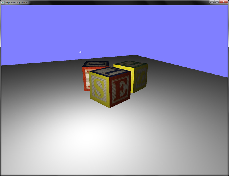
Chapter5/ObjViewer folder.
Let us start the recipe by following these simple steps:
- Create a global reference of the
ObjLoaderobject. Call theObjLoader::Loadfunction, passing it the name of the OBJ file. Pass vectors to store the meshes, vertices, indices, and materials contained in the OBJ file.ObjLoader obj; if(!obj.Load(mesh_filename.c_str(), meshes, vertices, indices, materials)) { cout<<"Cannot load the 3ds mesh"<<endl; exit(EXIT_FAILURE); } - Generate OpenGL texture objects for each material using the
SOILlibrary if the material has a texture map.for(size_t k=0;k<materials.size();k++) { if(materials[k]->map_Kd != "") { GLuint id = 0; glGenTextures(1, &id); glBindTexture(GL_TEXTURE_2D, id); glTexParameteri(GL_TEXTURE_2D, GL_TEXTURE_MIN_FILTER, GL_LINEAR); glTexParameteri(GL_TEXTURE_2D, GL_TEXTURE_MAG_FILTER, GL_LINEAR); glTexParameteri(GL_TEXTURE_2D, GL_TEXTURE_WRAP_S, GL_REPEAT); glTexParameteri(GL_TEXTURE_2D, GL_TEXTURE_WRAP_T, GL_REPEAT); int texture_width = 0, texture_height = 0, channels=0; const string& filename = materials[k]->map_Kd; std::string full_filename = mesh_path; full_filename.append(filename); GLubyte* pData = SOIL_load_image(full_filename.c_str(), &texture_width, &texture_height, &channels, SOIL_LOAD_AUTO); if(pData == NULL) { cerr<<"Cannot load image: "<<full_filename.c_str()<<endl; exit(EXIT_FAILURE); } //… image flipping code GLenum format = GL_RGBA; switch(channels) { case 2: format = GL_RG32UI; break; case 3: format = GL_RGB; break; case 4: format = GL_RGBA; break; } glTexImage2D(GL_TEXTURE_2D, 0, format, texture_width, texture_height, 0, format, GL_UNSIGNED_BYTE, pData); SOIL_free_image_data(pData); textures.push_back(id); } } - Set up shaders and generate buffer objects to store the mesh file data in the GPU memory. The shader setup is similar to the previous recipes.
glGenVertexArrays(1, &vaoID); glGenBuffers(1, &vboVerticesID); glGenBuffers(1, &vboIndicesID); glBindVertexArray(vaoID); glBindBuffer (GL_ARRAY_BUFFER, vboVerticesID); glBufferData (GL_ARRAY_BUFFER, sizeof(Vertex)*vertices.size(), &(vertices[0].pos.x), GL_STATIC_DRAW); glEnableVertexAttribArray(shader["vVertex"]); glVertexAttribPointer(shader["vVertex"], 3, GL_FLOAT, GL_FALSE,sizeof(Vertex),0); glEnableVertexAttribArray(shader["vNormal"]); glVertexAttribPointer(shader["vNormal"], 3, GL_FLOAT, GL_FALSE,sizeof(Vertex),(const GLvoid*)(offsetof( Vertex, normal)) ); glEnableVertexAttribArray(shader["vUV"]); glVertexAttribPointer(shader["vUV"], 2, GL_FLOAT, GL_FALSE, sizeof(Vertex), (const GLvoid*)(offsetof(Vertex, uv)) ); if(materials.size()==1) { glBindBuffer(GL_ELEMENT_ARRAY_BUFFER, vboIndicesID); glBufferData(GL_ELEMENT_ARRAY_BUFFER, sizeof(GLushort)*indices.size(), &(indices[0]), GL_STATIC_DRAW); }
- Bind the vertex array object associated with the mesh, use the shader and pass the shader uniforms, that is, the modelview (
MV), projection (P), normal matrices (N) and light position, and so on.glBindVertexArray(vaoID); { shader.Use(); glUniformMatrix4fv(shader("MV"), 1, GL_FALSE, glm::value_ptr(MV)); glUniformMatrix3fv(shader("N"), 1, GL_FALSE, glm::value_ptr(glm::inverseTranspose(glm::mat3(MV)))); glUniformMatrix4fv(shader("P"), 1, GL_FALSE, glm::value_ptr(P)); glUniform3fv(shader("light_position"),1, &(lightPosOS.x)); - To draw the mesh/submesh, loop through all of the materials in the mesh and then bind the texture to the
GL_TEXTURE_2Dtarget if the material contains a texture map. Otherwise, use a default color for the mesh. Finally, call theglDrawElementsfunction to render the mesh/submesh.for(size_t i=0;i<materials.size();i++) { Material* pMat = materials[i]; if(pMat->map_Kd !="") { glUniform1f(shader("useDefault"), 0.0); GLint whichID[1]; glGetIntegerv(GL_TEXTURE_BINDING_2D, whichID); if(whichID[0] != textures[i]) glBindTexture(GL_TEXTURE_2D, textures[i]); } else glUniform1f(shader("useDefault"), 1.0); if(materials.size()==1) glDrawElements(GL_TRIANGLES, indices.size(), GL_UNSIGNED_SHORT, 0); else glDrawElements(GL_TRIANGLES, pMat->count, GL_UNSIGNED_SHORT, (const GLvoid*)(& indices[pMat->offset])); } shader.UnUse();
Following the geometry definition, the topology is defined. In this case, the line is prefixed with f followed by the indices for the polygon vertices. In case of a triangle, three indices sections are given such that the vertex position indices are given first, followed by texture coordinates indices (if any), and finally the normal indices (if any). Note that the indices start from 1, not 0.
We generate the vertex array object and then the vertex buffer object. Next, we bind the buffer object passing it our vertices. In this case, we specify the stride of each attribute in the data stream separately as follows:
the recipe by following these simple steps:
- Create a global reference of the
ObjLoaderobject. Call theObjLoader::Loadfunction, passing it the name of the OBJ file. Pass vectors to store the meshes, vertices, indices, and materials contained in the OBJ file.ObjLoader obj; if(!obj.Load(mesh_filename.c_str(), meshes, vertices, indices, materials)) { cout<<"Cannot load the 3ds mesh"<<endl; exit(EXIT_FAILURE); } - Generate OpenGL texture objects for each material using the
SOILlibrary if the material has a texture map.for(size_t k=0;k<materials.size();k++) { if(materials[k]->map_Kd != "") { GLuint id = 0; glGenTextures(1, &id); glBindTexture(GL_TEXTURE_2D, id); glTexParameteri(GL_TEXTURE_2D, GL_TEXTURE_MIN_FILTER, GL_LINEAR); glTexParameteri(GL_TEXTURE_2D, GL_TEXTURE_MAG_FILTER, GL_LINEAR); glTexParameteri(GL_TEXTURE_2D, GL_TEXTURE_WRAP_S, GL_REPEAT); glTexParameteri(GL_TEXTURE_2D, GL_TEXTURE_WRAP_T, GL_REPEAT); int texture_width = 0, texture_height = 0, channels=0; const string& filename = materials[k]->map_Kd; std::string full_filename = mesh_path; full_filename.append(filename); GLubyte* pData = SOIL_load_image(full_filename.c_str(), &texture_width, &texture_height, &channels, SOIL_LOAD_AUTO); if(pData == NULL) { cerr<<"Cannot load image: "<<full_filename.c_str()<<endl; exit(EXIT_FAILURE); } //… image flipping code GLenum format = GL_RGBA; switch(channels) { case 2: format = GL_RG32UI; break; case 3: format = GL_RGB; break; case 4: format = GL_RGBA; break; } glTexImage2D(GL_TEXTURE_2D, 0, format, texture_width, texture_height, 0, format, GL_UNSIGNED_BYTE, pData); SOIL_free_image_data(pData); textures.push_back(id); } } - Set up shaders and generate buffer objects to store the mesh file data in the GPU memory. The shader setup is similar to the previous recipes.
glGenVertexArrays(1, &vaoID); glGenBuffers(1, &vboVerticesID); glGenBuffers(1, &vboIndicesID); glBindVertexArray(vaoID); glBindBuffer (GL_ARRAY_BUFFER, vboVerticesID); glBufferData (GL_ARRAY_BUFFER, sizeof(Vertex)*vertices.size(), &(vertices[0].pos.x), GL_STATIC_DRAW); glEnableVertexAttribArray(shader["vVertex"]); glVertexAttribPointer(shader["vVertex"], 3, GL_FLOAT, GL_FALSE,sizeof(Vertex),0); glEnableVertexAttribArray(shader["vNormal"]); glVertexAttribPointer(shader["vNormal"], 3, GL_FLOAT, GL_FALSE,sizeof(Vertex),(const GLvoid*)(offsetof( Vertex, normal)) ); glEnableVertexAttribArray(shader["vUV"]); glVertexAttribPointer(shader["vUV"], 2, GL_FLOAT, GL_FALSE, sizeof(Vertex), (const GLvoid*)(offsetof(Vertex, uv)) ); if(materials.size()==1) { glBindBuffer(GL_ELEMENT_ARRAY_BUFFER, vboIndicesID); glBufferData(GL_ELEMENT_ARRAY_BUFFER, sizeof(GLushort)*indices.size(), &(indices[0]), GL_STATIC_DRAW); }
- Bind the vertex array object associated with the mesh, use the shader and pass the shader uniforms, that is, the modelview (
MV), projection (P), normal matrices (N) and light position, and so on.glBindVertexArray(vaoID); { shader.Use(); glUniformMatrix4fv(shader("MV"), 1, GL_FALSE, glm::value_ptr(MV)); glUniformMatrix3fv(shader("N"), 1, GL_FALSE, glm::value_ptr(glm::inverseTranspose(glm::mat3(MV)))); glUniformMatrix4fv(shader("P"), 1, GL_FALSE, glm::value_ptr(P)); glUniform3fv(shader("light_position"),1, &(lightPosOS.x)); - To draw the mesh/submesh, loop through all of the materials in the mesh and then bind the texture to the
GL_TEXTURE_2Dtarget if the material contains a texture map. Otherwise, use a default color for the mesh. Finally, call theglDrawElementsfunction to render the mesh/submesh.for(size_t i=0;i<materials.size();i++) { Material* pMat = materials[i]; if(pMat->map_Kd !="") { glUniform1f(shader("useDefault"), 0.0); GLint whichID[1]; glGetIntegerv(GL_TEXTURE_BINDING_2D, whichID); if(whichID[0] != textures[i]) glBindTexture(GL_TEXTURE_2D, textures[i]); } else glUniform1f(shader("useDefault"), 1.0); if(materials.size()==1) glDrawElements(GL_TRIANGLES, indices.size(), GL_UNSIGNED_SHORT, 0); else glDrawElements(GL_TRIANGLES, pMat->count, GL_UNSIGNED_SHORT, (const GLvoid*)(& indices[pMat->offset])); } shader.UnUse();
Following the geometry definition, the topology is defined. In this case, the line is prefixed with f followed by the indices for the polygon vertices. In case of a triangle, three indices sections are given such that the vertex position indices are given first, followed by texture coordinates indices (if any), and finally the normal indices (if any). Note that the indices start from 1, not 0.
We generate the vertex array object and then the vertex buffer object. Next, we bind the buffer object passing it our vertices. In this case, we specify the stride of each attribute in the data stream separately as follows:
ObjLoader::Load function defined in the Obj.cpp file. The Wavefront® OBJ file is a text file which has different text descriptors for different mesh components. Usually, the mesh starts with the geometry definition, that is, vertices that begin with the letter v followed by three floating point values. If there are normals, their definitions begin with vn followed by three floating point values. If there are texture coordinates, their definitions begin with vt, followed by two floating point values. Comments start with the # character, so whenever a line with this character is encountered, it is ignored.
geometry definition, the topology is defined. In this case, the line is prefixed with f followed by the indices for the polygon vertices. In case of a triangle, three indices sections are given such that the vertex position indices are given first, followed by texture coordinates indices (if any), and finally the normal indices (if any). Note that the indices start from 1, not 0.
We generate the vertex array object and then the vertex buffer object. Next, we bind the buffer object passing it our vertices. In this case, we specify the stride of each attribute in the data stream separately as follows:
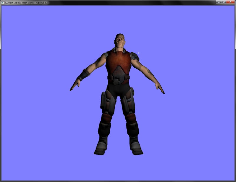
In this recipe, we will learn how to load and render an EZMesh model. There are several skeletal animation formats such as Quake's md2 (.md2), Autodesk® FBX (.fbx), and Collada (.dae). The conventional model formats such as Collada are overly complicated for doing simple skeletal animation. Therefore, in this recipe, we will learn how to load and render an EZMesh (.ezm) skeletal model.
The code for this recipe is contained in the Chapter5/EZMeshViewer directory. For this recipe, we will be using two external libraries to aid with the EZMesh (.ezm) mesh file parsing. The first library is called MeshImport and it can be downloaded from http://code.google.com/p/meshimport/. Make sure to get the latest svn trunk of the code. After downloading, change directory to the compiler subdirectory which contains the visual studio solution files. Double-click to open the solution and build the project dlls. After the library is built successfully, copy MeshImport_[x86/x64].dll and MeshImportEZM_[x86/x64].dll (subject to your machine configuration) into your current project directory. In addition, also copy the MeshImport.[h/cpp] files which contain some useful library loading routines.
In addition, since EZMesh is an XML format to support loading of textures, we parse the EZMesh XML manually with the help of the pugixml library. You can download it from http://pugixml.org/downloads/. As pugixml is tiny, we can directly include the source files with the project.
Let us start this recipe by following these simple steps:
- Create a global reference to an
EzmLoaderobject. Call theEzmLoader::Loadfunction passing it the name of the EZMesh (.ezm) file. Pass the vectors to store the submeshes, vertices, indices, and materials-to-image map. TheLoadfunction also accepts the min and max vectors to store the EZMesh bounding box.if(!ezm.Load(mesh_filename.c_str(), submeshes, vertices, indices, material2ImageMap, min, max)) { cout<<"Cannot load the EZMesh mesh"<<endl; exit(EXIT_FAILURE); } - Using the material information, generate the OpenGL textures for the EZMesh geometry.
for(size_t k=0;k<materialNames.size();k++) { GLuint id = 0; glGenTextures(1, &id); glBindTexture(GL_TEXTURE_2D, id); glTexParameteri(GL_TEXTURE_2D, GL_TEXTURE_MIN_FILTER, GL_LINEAR); glTexParameteri(GL_TEXTURE_2D, GL_TEXTURE_MAG_FILTER, GL_LINEAR); glTexParameteri(GL_TEXTURE_2D, GL_TEXTURE_WRAP_S, GL_REPEAT); glTexParameteri(GL_TEXTURE_2D, GL_TEXTURE_WRAP_T, GL_REPEAT); int texture_width = 0, texture_height = 0, channels=0; const string& filename = materialNames[k]; std::string full_filename = mesh_path; full_filename.append(filename); //Image loading using SOIL and vertical image flipping //… GLenum format = GL_RGBA; switch(channels) { case 2: format = GL_RG32UI; break; case 3: format = GL_RGB; break; case 4: format = GL_RGBA; break; } glTexImage2D(GL_TEXTURE_2D, 0, format, texture_width, texture_height, 0, format, GL_UNSIGNED_BYTE, pData); SOIL_free_image_data(pData); materialMap[filename] = id ; } - Set up the interleaved buffer object as in the previous recipe, Implementing OBJ model loading using interleaved buffers.
glBindVertexArray(vaoID); glBindBuffer (GL_ARRAY_BUFFER, vboVerticesID); glBufferData (GL_ARRAY_BUFFER, sizeof(Vertex)*vertices.size(), &(vertices[0].pos.x), GL_DYNAMIC_DRAW); glEnableVertexAttribArray(shader["vVertex"]); glVertexAttribPointer(shader["vVertex"], 3, GL_FLOAT, GL_FALSE,sizeof(Vertex),0); glEnableVertexAttribArray(shader["vNormal"]); glVertexAttribPointer(shader["vNormal"], 3, GL_FLOAT, GL_FALSE, sizeof(Vertex), (const GLvoid*)(offsetof(Vertex, normal)) ); glEnableVertexAttribArray(shader["vUV"]); glVertexAttribPointer(shader["vUV"], 2, GL_FLOAT, GL_FALSE, sizeof(Vertex), (const GLvoid*)(offsetof(Vertex, uv)) );
- To render the EZMesh, bind the mesh's vertex array object, set up the shader, and pass the shader uniforms.
glBindVertexArray(vaoID); { shader.Use(); glUniformMatrix4fv(shader("MV"), 1, GL_FALSE, glm::value_ptr(MV)); glUniformMatrix3fv(shader("N"), 1, GL_FALSE, glm::value_ptr(glm::inverseTranspose(glm::mat3(MV)))); glUniformMatrix4fv(shader("P"), 1, GL_FALSE, glm::value_ptr(P)); glUniform3fv(shader("light_position"),1, &(lightPosES.x)); - Loop through all submeshes, bind the submesh texture, and then issue the
glDrawEementscall, passing it the submesh indices. If the submesh has no materials, a default solid color material is assigned to the submesh.for(size_t i=0;i<submeshes.size();i++) { if(strlen(submeshes[i].materialName)>0) { GLuint id = materialMap[material2ImageMap[ submeshes[i].materialName]]; GLint whichID[1]; glGetIntegerv(GL_TEXTURE_BINDING_2D, whichID); if(whichID[0] != id) glBindTexture(GL_TEXTURE_2D, id); glUniform1f(shader("useDefault"), 0.0); } else { glUniform1f(shader("useDefault"), 1.0); } glDrawElements(GL_TRIANGLES, submeshes[i].indices.size(), GL_UNSIGNED_INT, &submeshes[i].indices[0]); } }
EZMesh is an XML based skeletal animation format. There are two parts to this recipe: parsing of the EZMesh file using the MeshImport/pugixml libraries and handling of the data using OpenGL buffer objects. The first part is handled by the EzmLoader::Load function. Along with the filename, this function accepts vectors to store the submeshes, vertices, indices, and material names map contained in the mesh file.
For this recipe, we are interested in the last two subelements: Materials and Meshes. We will be using the first two subelements in the skeletal animation recipe in a later chapter of this book. Each Materials element has a counted number of Material elements. Each Material element stores the material's name in the name attribute and the material's details. For example, the texture map file name in the meta_data attribute. In the EZMLoader::Load function, we use pugi_xml to parse the Materials element and its subelements into a material map. This map stores the material's name and its texture file name. Note that the MeshImport library does provide functions for reading material information, but they are broken.
Once we have the MeshSystem object, we can query all of the subelements. These reside in the MeshSystem object as member variables. So let's say we want to traverse through all of the meshes in the current EZMesh file and copy the per-vertex attributes to our own vector (vertices), we would simply do the following:
After the materials, the shaders are loaded as in the previous recipes. The per-vertex data is then transferred to the GPU using vertex array and vertex buffer objects. In this case, we use the interleaved vertex buffer format.
For rendering of the mesh, we first bind the vertex array object of the mesh, attach our shader and pass the shader uniforms. Then we loop over all of the submeshes and bind the appropriate texture (if the submesh has texture). Otherwise, a default color is used. Finally, the indices of the submesh are used to draw the mesh using the glDrawElements function.
Chapter5/EZMeshViewer directory. For this recipe, we will be using two external libraries to aid with the EZMesh (.ezm) mesh file parsing. The first library is called MeshImport and it can be downloaded from
http://code.google.com/p/meshimport/. Make sure to get the latest svn trunk of the code. After downloading, change directory to the compiler subdirectory which contains the visual studio solution files. Double-click to open the solution and build the project dlls. After the library is built successfully, copy MeshImport_[x86/x64].dll and MeshImportEZM_[x86/x64].dll (subject to your machine configuration) into your current project directory. In addition, also copy the MeshImport.[h/cpp] files which contain some useful library loading routines.
In addition, since EZMesh is an XML format to support loading of textures, we parse the EZMesh XML manually with the help of the pugixml library. You can download it from http://pugixml.org/downloads/. As pugixml is tiny, we can directly include the source files with the project.
Let us start this recipe by following these simple steps:
- Create a global reference to an
EzmLoaderobject. Call theEzmLoader::Loadfunction passing it the name of the EZMesh (.ezm) file. Pass the vectors to store the submeshes, vertices, indices, and materials-to-image map. TheLoadfunction also accepts the min and max vectors to store the EZMesh bounding box.if(!ezm.Load(mesh_filename.c_str(), submeshes, vertices, indices, material2ImageMap, min, max)) { cout<<"Cannot load the EZMesh mesh"<<endl; exit(EXIT_FAILURE); } - Using the material information, generate the OpenGL textures for the EZMesh geometry.
for(size_t k=0;k<materialNames.size();k++) { GLuint id = 0; glGenTextures(1, &id); glBindTexture(GL_TEXTURE_2D, id); glTexParameteri(GL_TEXTURE_2D, GL_TEXTURE_MIN_FILTER, GL_LINEAR); glTexParameteri(GL_TEXTURE_2D, GL_TEXTURE_MAG_FILTER, GL_LINEAR); glTexParameteri(GL_TEXTURE_2D, GL_TEXTURE_WRAP_S, GL_REPEAT); glTexParameteri(GL_TEXTURE_2D, GL_TEXTURE_WRAP_T, GL_REPEAT); int texture_width = 0, texture_height = 0, channels=0; const string& filename = materialNames[k]; std::string full_filename = mesh_path; full_filename.append(filename); //Image loading using SOIL and vertical image flipping //… GLenum format = GL_RGBA; switch(channels) { case 2: format = GL_RG32UI; break; case 3: format = GL_RGB; break; case 4: format = GL_RGBA; break; } glTexImage2D(GL_TEXTURE_2D, 0, format, texture_width, texture_height, 0, format, GL_UNSIGNED_BYTE, pData); SOIL_free_image_data(pData); materialMap[filename] = id ; } - Set up the interleaved buffer object as in the previous recipe, Implementing OBJ model loading using interleaved buffers.
glBindVertexArray(vaoID); glBindBuffer (GL_ARRAY_BUFFER, vboVerticesID); glBufferData (GL_ARRAY_BUFFER, sizeof(Vertex)*vertices.size(), &(vertices[0].pos.x), GL_DYNAMIC_DRAW); glEnableVertexAttribArray(shader["vVertex"]); glVertexAttribPointer(shader["vVertex"], 3, GL_FLOAT, GL_FALSE,sizeof(Vertex),0); glEnableVertexAttribArray(shader["vNormal"]); glVertexAttribPointer(shader["vNormal"], 3, GL_FLOAT, GL_FALSE, sizeof(Vertex), (const GLvoid*)(offsetof(Vertex, normal)) ); glEnableVertexAttribArray(shader["vUV"]); glVertexAttribPointer(shader["vUV"], 2, GL_FLOAT, GL_FALSE, sizeof(Vertex), (const GLvoid*)(offsetof(Vertex, uv)) );
- To render the EZMesh, bind the mesh's vertex array object, set up the shader, and pass the shader uniforms.
glBindVertexArray(vaoID); { shader.Use(); glUniformMatrix4fv(shader("MV"), 1, GL_FALSE, glm::value_ptr(MV)); glUniformMatrix3fv(shader("N"), 1, GL_FALSE, glm::value_ptr(glm::inverseTranspose(glm::mat3(MV)))); glUniformMatrix4fv(shader("P"), 1, GL_FALSE, glm::value_ptr(P)); glUniform3fv(shader("light_position"),1, &(lightPosES.x)); - Loop through all submeshes, bind the submesh texture, and then issue the
glDrawEementscall, passing it the submesh indices. If the submesh has no materials, a default solid color material is assigned to the submesh.for(size_t i=0;i<submeshes.size();i++) { if(strlen(submeshes[i].materialName)>0) { GLuint id = materialMap[material2ImageMap[ submeshes[i].materialName]]; GLint whichID[1]; glGetIntegerv(GL_TEXTURE_BINDING_2D, whichID); if(whichID[0] != id) glBindTexture(GL_TEXTURE_2D, id); glUniform1f(shader("useDefault"), 0.0); } else { glUniform1f(shader("useDefault"), 1.0); } glDrawElements(GL_TRIANGLES, submeshes[i].indices.size(), GL_UNSIGNED_INT, &submeshes[i].indices[0]); } }
EZMesh is an XML based skeletal animation format. There are two parts to this recipe: parsing of the EZMesh file using the MeshImport/pugixml libraries and handling of the data using OpenGL buffer objects. The first part is handled by the EzmLoader::Load function. Along with the filename, this function accepts vectors to store the submeshes, vertices, indices, and material names map contained in the mesh file.
For this recipe, we are interested in the last two subelements: Materials and Meshes. We will be using the first two subelements in the skeletal animation recipe in a later chapter of this book. Each Materials element has a counted number of Material elements. Each Material element stores the material's name in the name attribute and the material's details. For example, the texture map file name in the meta_data attribute. In the EZMLoader::Load function, we use pugi_xml to parse the Materials element and its subelements into a material map. This map stores the material's name and its texture file name. Note that the MeshImport library does provide functions for reading material information, but they are broken.
Once we have the MeshSystem object, we can query all of the subelements. These reside in the MeshSystem object as member variables. So let's say we want to traverse through all of the meshes in the current EZMesh file and copy the per-vertex attributes to our own vector (vertices), we would simply do the following:
After the materials, the shaders are loaded as in the previous recipes. The per-vertex data is then transferred to the GPU using vertex array and vertex buffer objects. In this case, we use the interleaved vertex buffer format.
For rendering of the mesh, we first bind the vertex array object of the mesh, attach our shader and pass the shader uniforms. Then we loop over all of the submeshes and bind the appropriate texture (if the submesh has texture). Otherwise, a default color is used. Finally, the indices of the submesh are used to draw the mesh using the glDrawElements function.
recipe by following these simple steps:
- Create a global reference to an
EzmLoaderobject. Call theEzmLoader::Loadfunction passing it the name of the EZMesh (.ezm) file. Pass the vectors to store the submeshes, vertices, indices, and materials-to-image map. TheLoadfunction also accepts the min and max vectors to store the EZMesh bounding box.if(!ezm.Load(mesh_filename.c_str(), submeshes, vertices, indices, material2ImageMap, min, max)) { cout<<"Cannot load the EZMesh mesh"<<endl; exit(EXIT_FAILURE); } - Using the material information, generate the OpenGL textures for the EZMesh geometry.
for(size_t k=0;k<materialNames.size();k++) { GLuint id = 0; glGenTextures(1, &id); glBindTexture(GL_TEXTURE_2D, id); glTexParameteri(GL_TEXTURE_2D, GL_TEXTURE_MIN_FILTER, GL_LINEAR); glTexParameteri(GL_TEXTURE_2D, GL_TEXTURE_MAG_FILTER, GL_LINEAR); glTexParameteri(GL_TEXTURE_2D, GL_TEXTURE_WRAP_S, GL_REPEAT); glTexParameteri(GL_TEXTURE_2D, GL_TEXTURE_WRAP_T, GL_REPEAT); int texture_width = 0, texture_height = 0, channels=0; const string& filename = materialNames[k]; std::string full_filename = mesh_path; full_filename.append(filename); //Image loading using SOIL and vertical image flipping //… GLenum format = GL_RGBA; switch(channels) { case 2: format = GL_RG32UI; break; case 3: format = GL_RGB; break; case 4: format = GL_RGBA; break; } glTexImage2D(GL_TEXTURE_2D, 0, format, texture_width, texture_height, 0, format, GL_UNSIGNED_BYTE, pData); SOIL_free_image_data(pData); materialMap[filename] = id ; } - Set up the interleaved buffer object as in the previous recipe, Implementing OBJ model loading using interleaved buffers.
glBindVertexArray(vaoID); glBindBuffer (GL_ARRAY_BUFFER, vboVerticesID); glBufferData (GL_ARRAY_BUFFER, sizeof(Vertex)*vertices.size(), &(vertices[0].pos.x), GL_DYNAMIC_DRAW); glEnableVertexAttribArray(shader["vVertex"]); glVertexAttribPointer(shader["vVertex"], 3, GL_FLOAT, GL_FALSE,sizeof(Vertex),0); glEnableVertexAttribArray(shader["vNormal"]); glVertexAttribPointer(shader["vNormal"], 3, GL_FLOAT, GL_FALSE, sizeof(Vertex), (const GLvoid*)(offsetof(Vertex, normal)) ); glEnableVertexAttribArray(shader["vUV"]); glVertexAttribPointer(shader["vUV"], 2, GL_FLOAT, GL_FALSE, sizeof(Vertex), (const GLvoid*)(offsetof(Vertex, uv)) );
- To render the EZMesh, bind the mesh's vertex array object, set up the shader, and pass the shader uniforms.
glBindVertexArray(vaoID); { shader.Use(); glUniformMatrix4fv(shader("MV"), 1, GL_FALSE, glm::value_ptr(MV)); glUniformMatrix3fv(shader("N"), 1, GL_FALSE, glm::value_ptr(glm::inverseTranspose(glm::mat3(MV)))); glUniformMatrix4fv(shader("P"), 1, GL_FALSE, glm::value_ptr(P)); glUniform3fv(shader("light_position"),1, &(lightPosES.x)); - Loop through all submeshes, bind the submesh texture, and then issue the
glDrawEementscall, passing it the submesh indices. If the submesh has no materials, a default solid color material is assigned to the submesh.for(size_t i=0;i<submeshes.size();i++) { if(strlen(submeshes[i].materialName)>0) { GLuint id = materialMap[material2ImageMap[ submeshes[i].materialName]]; GLint whichID[1]; glGetIntegerv(GL_TEXTURE_BINDING_2D, whichID); if(whichID[0] != id) glBindTexture(GL_TEXTURE_2D, id); glUniform1f(shader("useDefault"), 0.0); } else { glUniform1f(shader("useDefault"), 1.0); } glDrawElements(GL_TRIANGLES, submeshes[i].indices.size(), GL_UNSIGNED_INT, &submeshes[i].indices[0]); } }
EZMesh is an XML based skeletal animation format. There are two parts to this recipe: parsing of the EZMesh file using the MeshImport/pugixml libraries and handling of the data using OpenGL buffer objects. The first part is handled by the EzmLoader::Load function. Along with the filename, this function accepts vectors to store the submeshes, vertices, indices, and material names map contained in the mesh file.
For this recipe, we are interested in the last two subelements: Materials and Meshes. We will be using the first two subelements in the skeletal animation recipe in a later chapter of this book. Each Materials element has a counted number of Material elements. Each Material element stores the material's name in the name attribute and the material's details. For example, the texture map file name in the meta_data attribute. In the EZMLoader::Load function, we use pugi_xml to parse the Materials element and its subelements into a material map. This map stores the material's name and its texture file name. Note that the MeshImport library does provide functions for reading material information, but they are broken.
Once we have the MeshSystem object, we can query all of the subelements. These reside in the MeshSystem object as member variables. So let's say we want to traverse through all of the meshes in the current EZMesh file and copy the per-vertex attributes to our own vector (vertices), we would simply do the following:
After the materials, the shaders are loaded as in the previous recipes. The per-vertex data is then transferred to the GPU using vertex array and vertex buffer objects. In this case, we use the interleaved vertex buffer format.
For rendering of the mesh, we first bind the vertex array object of the mesh, attach our shader and pass the shader uniforms. Then we loop over all of the submeshes and bind the appropriate texture (if the submesh has texture). Otherwise, a default color is used. Finally, the indices of the submesh are used to draw the mesh using the glDrawElements function.
In this recipe, we will implement a simple particle system. Particle systems are a special category of objects that enable us to simulate fuzzy effects in computer graphics; for example, fire or smoke. In this recipe, we will implement a simple particle system that emits particles at the specified rate from an oriented emitter. In this recipe, we will assign particles with a basic fire color map without texture, to give the effect of fire.
The code for this recipe is contained in the Chapter5/SimpleParticles directory. All of the work for particle simulation is carried out in the vertex shader.
Let us start this recipe by following these simple steps:
- Create a vertex shader without any per-vertex attribute. The vertex shader generates the current particle position and outputs a smooth color to the fragment shader for use as the current fragment color.
#version 330 core smooth out vec4 vSmoothColor; uniform mat4 MVP; uniform float time; const vec3 a = vec3(0,2,0); //acceleration of particles //vec3 g = vec3(0,-9.8,0); // acceleration due to gravity const float rate = 1/500.0; //rate of emission const float life = 2; //life of particle //constants const float PI = 3.14159; const float TWO_PI = 2*PI; //colormap colours const vec3 RED = vec3(1,0,0); const vec3 GREEN = vec3(0,1,0); const vec3 YELLOW = vec3(1,1,0); //pseudorandom number generator float rand(vec2 co){ return fract(sin(dot(co.xy ,vec2(12.9898,78.233))) * 43758.5453); } //pseudorandom direction on a sphere vec3 uniformRadomDir(vec2 v, out vec2 r) { r.x = rand(v.xy); r.y = rand(v.yx); float theta = mix(0.0, PI / 6.0, r.x); float phi = mix(0.0, TWO_PI, r.y); return vec3(sin(theta) * cos(phi), cos(theta), sin(theta) * sin(phi)); } void main() { vec3 pos=vec3(0); float t = gl_VertexID*rate; float alpha = 1; if(time>t) { float dt = mod((time-t), life); vec2 xy = vec2(gl_VertexID,t); vec2 rdm=vec2(0); pos = ((uniformRadomDir(xy, rdm) + 0.5*a*dt)*dt); alpha = 1.0 - (dt/life); } vSmoothColor = vec4(mix(RED,YELLOW,alpha),alpha); gl_Position = MVP*vec4(pos,1); } - The fragment shader outputs the smooth color as the current fragment output color.
#version 330 core smooth in vec4 vSmoothColor; layout(location=0) out vec4 vFragColor; void main() { vFragColor = vSmoothColor; } - Set up a single vertex array object and bind it.
glGenVertexArrays(1, &vaoID); glBindVertexArray(vaoID);
- In the rendering code, set up the shader and pass the shader uniforms. For example, pass the current time to the
timeshader uniform and the combined modelview projection matrix (MVP). Here we add an emitter transform matrix (emitterXForm) to the combinedMVPmatrix that controls the orientation of our particle emitter.shader.Use(); glUniform1f(shader("time"), time); glUniformMatrix4fv(shader("MVP"), 1, GL_FALSE, glm::value_ptr(P*MV*emitterXForm)); - Finally, we render the total number of particles (
MAX_PARTICLES) with a call to theglDrawArraysfunction and unbind our shader.glDrawArrays(GL_POINTS, 0, MAX_PARTICLES); shader.UnUse();
We have two uniforms in the vertex shader, the combined modelview projection matrix (MVP) and the current simulation time (time). The other variables required for particle simulation are stored as shader constants.
The alpha value is used to linearly interpolate between red and yellow colors by calling the GLSL mix function to give the fire effect. Finally, the generated position is multiplied with the combined modelview projection (MVP) matrix to get the clip space position of the particle.
The application loads a particle texture and generates an OpenGL texture object from it.
Next, the texture unit to which the texture is bound is passed to the shader.
Finally, the particles are rendered using the glDrawArrays call as shown earlier.
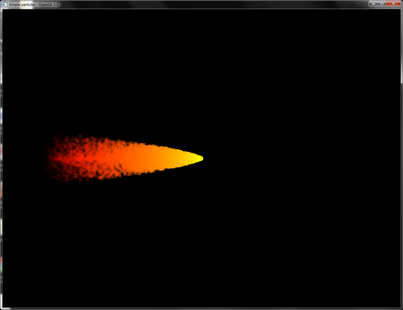
If the textured particles shader is used, we get the following output:
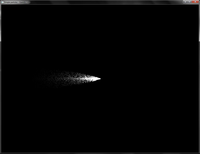
The orientation and position of the emitter is controlled using the emitter transformation matrix (emitterXForm). We can change this matrix to reorient/reposition the particle system in the 3D space.
This gives the following output:
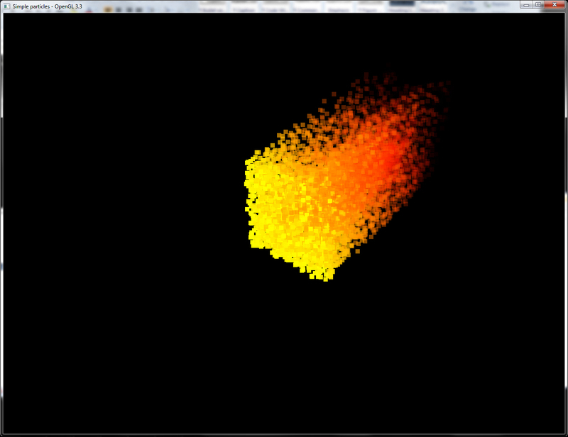
Changing the emitter to a disc shape further filters the points spawned in the rectangle emitter by only accepting those which lie inside the circle of a given radius, as given in the following code snippet:
Using this position calculation gives a disc emitter as shown in the following output:

We can also add additional forces such as air drag, wind, vortex, and so on, by simply adding to the acceleration or velocity component of the particle system. Another option could be to direct the emitter to a specific path such as a b-spline. We could also add deflectors to deflect the generated particles or create particles that spawn other particles as is typically used in a fireworks particle system. Particle systems are an extremely interesting area in computer graphics which help us obtain wonderful effects easily.
To know more about detailed effects you can refer to the following links:
- Real-time particle systems on the GPU in Dynamic Environment SIGGRAPH 2007 Talk: http://developer.amd.com/wordpress/media/2012/10/Drone-Real-Time_Particles_Systems_on_the_GPU_in_Dynamic_Environments%28Siggraph07%29.pdf
- GPU Gems 3 Chapter 23-High speed offscreen particles: http://http.developer.nvidia.com/GPUGems3/gpugems3_ch23.html
- Building a million particle system by Lutz Latta: http://www.gamasutra.com/view/feature/130535/building_a_millionparticle_system.php?print=1
- CG Tutorial chapter 6: http://http.developer.nvidia.com/CgTutorial/cg_tutorial_chapter06.html
Let us start this recipe by following these simple steps:
- Create a vertex shader without any per-vertex attribute. The vertex shader generates the current particle position and outputs a smooth color to the fragment shader for use as the current fragment color.
#version 330 core smooth out vec4 vSmoothColor; uniform mat4 MVP; uniform float time; const vec3 a = vec3(0,2,0); //acceleration of particles //vec3 g = vec3(0,-9.8,0); // acceleration due to gravity const float rate = 1/500.0; //rate of emission const float life = 2; //life of particle //constants const float PI = 3.14159; const float TWO_PI = 2*PI; //colormap colours const vec3 RED = vec3(1,0,0); const vec3 GREEN = vec3(0,1,0); const vec3 YELLOW = vec3(1,1,0); //pseudorandom number generator float rand(vec2 co){ return fract(sin(dot(co.xy ,vec2(12.9898,78.233))) * 43758.5453); } //pseudorandom direction on a sphere vec3 uniformRadomDir(vec2 v, out vec2 r) { r.x = rand(v.xy); r.y = rand(v.yx); float theta = mix(0.0, PI / 6.0, r.x); float phi = mix(0.0, TWO_PI, r.y); return vec3(sin(theta) * cos(phi), cos(theta), sin(theta) * sin(phi)); } void main() { vec3 pos=vec3(0); float t = gl_VertexID*rate; float alpha = 1; if(time>t) { float dt = mod((time-t), life); vec2 xy = vec2(gl_VertexID,t); vec2 rdm=vec2(0); pos = ((uniformRadomDir(xy, rdm) + 0.5*a*dt)*dt); alpha = 1.0 - (dt/life); } vSmoothColor = vec4(mix(RED,YELLOW,alpha),alpha); gl_Position = MVP*vec4(pos,1); } - The fragment shader outputs the smooth color as the current fragment output color.
#version 330 core smooth in vec4 vSmoothColor; layout(location=0) out vec4 vFragColor; void main() { vFragColor = vSmoothColor; } - Set up a single vertex array object and bind it.
glGenVertexArrays(1, &vaoID); glBindVertexArray(vaoID);
- In the rendering code, set up the shader and pass the shader uniforms. For example, pass the current time to the
timeshader uniform and the combined modelview projection matrix (MVP). Here we add an emitter transform matrix (emitterXForm) to the combinedMVPmatrix that controls the orientation of our particle emitter.shader.Use(); glUniform1f(shader("time"), time); glUniformMatrix4fv(shader("MVP"), 1, GL_FALSE, glm::value_ptr(P*MV*emitterXForm)); - Finally, we render the total number of particles (
MAX_PARTICLES) with a call to theglDrawArraysfunction and unbind our shader.glDrawArrays(GL_POINTS, 0, MAX_PARTICLES); shader.UnUse();
We have two uniforms in the vertex shader, the combined modelview projection matrix (MVP) and the current simulation time (time). The other variables required for particle simulation are stored as shader constants.
The alpha value is used to linearly interpolate between red and yellow colors by calling the GLSL mix function to give the fire effect. Finally, the generated position is multiplied with the combined modelview projection (MVP) matrix to get the clip space position of the particle.
The application loads a particle texture and generates an OpenGL texture object from it.
Next, the texture unit to which the texture is bound is passed to the shader.
Finally, the particles are rendered using the glDrawArrays call as shown earlier.
If the textured particles shader is used, we get the following output:
The orientation and position of the emitter is controlled using the emitter transformation matrix (emitterXForm). We can change this matrix to reorient/reposition the particle system in the 3D space.
This gives the following output:
Changing the emitter to a disc shape further filters the points spawned in the rectangle emitter by only accepting those which lie inside the circle of a given radius, as given in the following code snippet:
Using this position calculation gives a disc emitter as shown in the following output:
We can also add additional forces such as air drag, wind, vortex, and so on, by simply adding to the acceleration or velocity component of the particle system. Another option could be to direct the emitter to a specific path such as a b-spline. We could also add deflectors to deflect the generated particles or create particles that spawn other particles as is typically used in a fireworks particle system. Particle systems are an extremely interesting area in computer graphics which help us obtain wonderful effects easily.
To know more about detailed effects you can refer to the following links:
- Real-time particle systems on the GPU in Dynamic Environment SIGGRAPH 2007 Talk: http://developer.amd.com/wordpress/media/2012/10/Drone-Real-Time_Particles_Systems_on_the_GPU_in_Dynamic_Environments%28Siggraph07%29.pdf
- GPU Gems 3 Chapter 23-High speed offscreen particles: http://http.developer.nvidia.com/GPUGems3/gpugems3_ch23.html
- Building a million particle system by Lutz Latta: http://www.gamasutra.com/view/feature/130535/building_a_millionparticle_system.php?print=1
- CG Tutorial chapter 6: http://http.developer.nvidia.com/CgTutorial/cg_tutorial_chapter06.html
- for use as the current fragment color.
#version 330 core smooth out vec4 vSmoothColor; uniform mat4 MVP; uniform float time; const vec3 a = vec3(0,2,0); //acceleration of particles //vec3 g = vec3(0,-9.8,0); // acceleration due to gravity const float rate = 1/500.0; //rate of emission const float life = 2; //life of particle //constants const float PI = 3.14159; const float TWO_PI = 2*PI; //colormap colours const vec3 RED = vec3(1,0,0); const vec3 GREEN = vec3(0,1,0); const vec3 YELLOW = vec3(1,1,0); //pseudorandom number generator float rand(vec2 co){ return fract(sin(dot(co.xy ,vec2(12.9898,78.233))) * 43758.5453); } //pseudorandom direction on a sphere vec3 uniformRadomDir(vec2 v, out vec2 r) { r.x = rand(v.xy); r.y = rand(v.yx); float theta = mix(0.0, PI / 6.0, r.x); float phi = mix(0.0, TWO_PI, r.y); return vec3(sin(theta) * cos(phi), cos(theta), sin(theta) * sin(phi)); } void main() { vec3 pos=vec3(0); float t = gl_VertexID*rate; float alpha = 1; if(time>t) { float dt = mod((time-t), life); vec2 xy = vec2(gl_VertexID,t); vec2 rdm=vec2(0); pos = ((uniformRadomDir(xy, rdm) + 0.5*a*dt)*dt); alpha = 1.0 - (dt/life); } vSmoothColor = vec4(mix(RED,YELLOW,alpha),alpha); gl_Position = MVP*vec4(pos,1); } - The fragment shader outputs the smooth color as the current fragment output color.
#version 330 core smooth in vec4 vSmoothColor; layout(location=0) out vec4 vFragColor; void main() { vFragColor = vSmoothColor; } - Set up a single vertex array object and bind it.
glGenVertexArrays(1, &vaoID); glBindVertexArray(vaoID);
- In the rendering code, set up the shader and pass the shader uniforms. For example, pass the current time to the
timeshader uniform and the combined modelview projection matrix (MVP). Here we add an emitter transform matrix (emitterXForm) to the combinedMVPmatrix that controls the orientation of our particle emitter.shader.Use(); glUniform1f(shader("time"), time); glUniformMatrix4fv(shader("MVP"), 1, GL_FALSE, glm::value_ptr(P*MV*emitterXForm)); - Finally, we render the total number of particles (
MAX_PARTICLES) with a call to theglDrawArraysfunction and unbind our shader.glDrawArrays(GL_POINTS, 0, MAX_PARTICLES); shader.UnUse();
We have two uniforms in the vertex shader, the combined modelview projection matrix (MVP) and the current simulation time (time). The other variables required for particle simulation are stored as shader constants.
The alpha value is used to linearly interpolate between red and yellow colors by calling the GLSL mix function to give the fire effect. Finally, the generated position is multiplied with the combined modelview projection (MVP) matrix to get the clip space position of the particle.
The application loads a particle texture and generates an OpenGL texture object from it.
Next, the texture unit to which the texture is bound is passed to the shader.
Finally, the particles are rendered using the glDrawArrays call as shown earlier.
If the textured particles shader is used, we get the following output:
The orientation and position of the emitter is controlled using the emitter transformation matrix (emitterXForm). We can change this matrix to reorient/reposition the particle system in the 3D space.
This gives the following output:
Changing the emitter to a disc shape further filters the points spawned in the rectangle emitter by only accepting those which lie inside the circle of a given radius, as given in the following code snippet:
Using this position calculation gives a disc emitter as shown in the following output:
We can also add additional forces such as air drag, wind, vortex, and so on, by simply adding to the acceleration or velocity component of the particle system. Another option could be to direct the emitter to a specific path such as a b-spline. We could also add deflectors to deflect the generated particles or create particles that spawn other particles as is typically used in a fireworks particle system. Particle systems are an extremely interesting area in computer graphics which help us obtain wonderful effects easily.
To know more about detailed effects you can refer to the following links:
- Real-time particle systems on the GPU in Dynamic Environment SIGGRAPH 2007 Talk: http://developer.amd.com/wordpress/media/2012/10/Drone-Real-Time_Particles_Systems_on_the_GPU_in_Dynamic_Environments%28Siggraph07%29.pdf
- GPU Gems 3 Chapter 23-High speed offscreen particles: http://http.developer.nvidia.com/GPUGems3/gpugems3_ch23.html
- Building a million particle system by Lutz Latta: http://www.gamasutra.com/view/feature/130535/building_a_millionparticle_system.php?print=1
- CG Tutorial chapter 6: http://http.developer.nvidia.com/CgTutorial/cg_tutorial_chapter06.html
glDrawArrays call with the number of particles (MAX_PARTICLES) we need to render. This calls our vertex shader for each particle in turn.
The alpha value is used to linearly interpolate between red and yellow colors by calling the GLSL mix function to give the fire effect. Finally, the generated position is multiplied with the combined modelview projection (MVP) matrix to get the clip space position of the particle.
The application loads a particle texture and generates an OpenGL texture object from it.
Next, the texture unit to which the texture is bound is passed to the shader.
Finally, the particles are rendered using the glDrawArrays call as shown earlier.
If the textured particles shader is used, we get the following output:
The orientation and position of the emitter is controlled using the emitter transformation matrix (emitterXForm). We can change this matrix to reorient/reposition the particle system in the 3D space.
This gives the following output:
Changing the emitter to a disc shape further filters the points spawned in the rectangle emitter by only accepting those which lie inside the circle of a given radius, as given in the following code snippet:
Using this position calculation gives a disc emitter as shown in the following output:
We can also add additional forces such as air drag, wind, vortex, and so on, by simply adding to the acceleration or velocity component of the particle system. Another option could be to direct the emitter to a specific path such as a b-spline. We could also add deflectors to deflect the generated particles or create particles that spawn other particles as is typically used in a fireworks particle system. Particle systems are an extremely interesting area in computer graphics which help us obtain wonderful effects easily.
To know more about detailed effects you can refer to the following links:
- Real-time particle systems on the GPU in Dynamic Environment SIGGRAPH 2007 Talk: http://developer.amd.com/wordpress/media/2012/10/Drone-Real-Time_Particles_Systems_on_the_GPU_in_Dynamic_Environments%28Siggraph07%29.pdf
- GPU Gems 3 Chapter 23-High speed offscreen particles: http://http.developer.nvidia.com/GPUGems3/gpugems3_ch23.html
- Building a million particle system by Lutz Latta: http://www.gamasutra.com/view/feature/130535/building_a_millionparticle_system.php?print=1
- CG Tutorial chapter 6: http://http.developer.nvidia.com/CgTutorial/cg_tutorial_chapter06.html
- http://developer.amd.com/wordpress/media/2012/10/Drone-Real-Time_Particles_Systems_on_the_GPU_in_Dynamic_Environments%28Siggraph07%29.pdf
- GPU Gems 3 Chapter 23-High speed offscreen particles: http://http.developer.nvidia.com/GPUGems3/gpugems3_ch23.html
- Building a million particle system by Lutz Latta: http://www.gamasutra.com/view/feature/130535/building_a_millionparticle_system.php?print=1
- CG Tutorial chapter 6: http://http.developer.nvidia.com/CgTutorial/cg_tutorial_chapter06.html