

In this chapter, we will cover:
- Implementing per-vertex and per-fragment point lighting
- Implementing per-fragment directional light
- Implementing per-fragment point light with attenuation
- Implementing per-fragment spot light
- Implementing shadow mapping with FBO
- Implementing shadow mapping with percentage closer filtering (PCF)
- Implementing variance shadow mapping
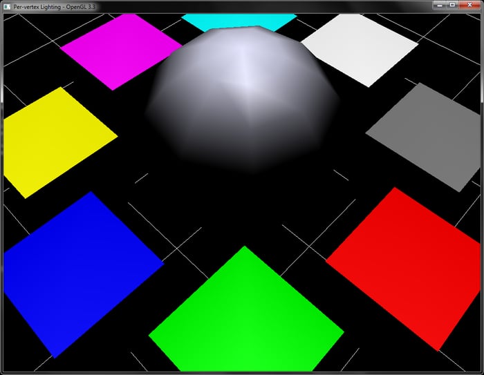
To give more realism to 3D graphic scenes, we add lighting. In OpenGL's fixed function pipeline, per-vertex lighting is provided (which is deprecated in OpenGL v3.3 and above). Using shaders, we can not only replicate the per-vertex lighting of fixed function pipeline but also go a step further by implementing per-fragment lighting. The per-vertex lighting is also known as Gouraud shading and the per-fragment shading is known as Phong shading. So, without further ado, let's get started.
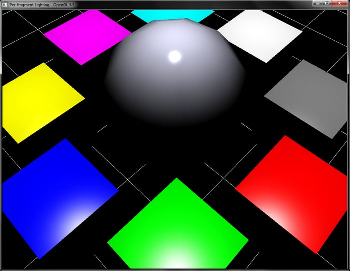
In this recipe, we will render many cubes and a sphere. All of these objects are generated and stored in the buffer objects. For details, refer to the CreateSphere and CreateCube functions in Chapter4/PerVertexLighting/main.cpp. These functions generate both vertex positions as well as per-vertex normals, which are needed for the lighting calculations. All of the lighting calculations take place in the vertex shader of the per-vertex lighting recipe (Chapter4/PerVertexLighting/), whereas, for the per-fragment lighting recipe (Chapter4/PerFragmentLighting/) they take place in the fragment shader.
Let us start our recipe by following these simple steps:
- Set up the vertex shader that performs the lighting calculation in the view/eye space. This generates the color after the lighting calculation.
#version 330 core layout(location=0) in vec3 vVertex; layout(location=1) in vec3 vNormal; uniform mat4 MVP; uniform mat4 MV; uniform mat3 N; uniform vec3 light_position; //light position in object space uniform vec3 diffuse_color; uniform vec3 specular_color; uniform float shininess; smooth out vec4 color; const vec3 vEyeSpaceCameraPosition = vec3(0,0,0); void main() { vec4 vEyeSpaceLightPosition = MV*vec4(light_position,1); vec4 vEyeSpacePosition = MV*vec4(vVertex,1); vec3 vEyeSpaceNormal = normalize(N*vNormal); vec3 L = normalize(vEyeSpaceLightPosition.xyz –vEyeSpacePosition.xyz); vec3 V = normalize(vEyeSpaceCameraPosition.xyz- vEyeSpacePosition.xyz); vec3 H = normalize(L+V); float diffuse = max(0, dot(vEyeSpaceNormal, L)); float specular = max(0, pow(dot(vEyeSpaceNormal, H), shininess)); color = diffuse*vec4(diffuse_color,1) + specular*vec4(specular_color, 1); gl_Position = MVP*vec4(vVertex,1); } - Set up a fragment shader which, inputs the shaded color from the vertex shader interpolated by the rasterizer, and set it as the current output color.
#version 330 core layout(location=0) out vec4 vFragColor; smooth in vec4 color; void main() { vFragColor = color; } - In the rendering code, set the shader and render the objects by passing their modelview/projection matrices to the shader as shader uniforms.
shader.Use(); glBindVertexArray(cubeVAOID); for(int i=0;i<8;i++) { float theta = (float)(i/8.0f*2*M_PI); glm::mat4 T = glm::translate(glm::mat4(1), glm::vec3(radius*cos(theta), 0.5,radius*sin(theta))); glm::mat4 M = T; glm::mat4 MV = View*M; glm::mat4 MVP = Proj*MV; glUniformMatrix4fv(shader("MVP"), 1, GL_FALSE, glm::value_ptr(MVP)); glUniformMatrix4fv(shader("MV"), 1, GL_FALSE, glm::value_ptr(MV)); glUniformMatrix3fv(shader("N"), 1, GL_FALSE, glm::value_ptr(glm::inverseTranspose(glm::mat3(MV)))); glUniform3fv(shader("diffuse_color"),1, &(colors[i].x)); glUniform3fv(shader("light_position"),1,&(lightPosOS.x)); glDrawElements(GL_TRIANGLES, 36, GL_UNSIGNED_SHORT, 0); } glBindVertexArray(sphereVAOID); glm::mat4 T = glm::translate(glm::mat4(1), glm::vec3(0,1,0)); glm::mat4 M = T; glm::mat4 MV = View*M; glm::mat4 MVP = Proj*MV; glUniformMatrix4fv(shader("MVP"), 1, GL_FALSE, glm::value_ptr(MVP)); glUniformMatrix4fv(shader("MV"), 1, GL_FALSE, glm::value_ptr(MV)); glUniformMatrix3fv(shader("N"), 1, GL_FALSE, glm::value_ptr(glm::inverseTranspose(glm::mat3(MV)))); glUniform3f(shader("diffuse_color"), 0.9f, 0.9f, 1.0f); glUniform3fv(shader("light_position"),1, &(lightPosOS.x)); glDrawElements(GL_TRIANGLES, totalSphereTriangles, GL_UNSIGNED_SHORT, 0); shader.UnUse(); glBindVertexArray(0); grid->Render(glm::value_ptr(Proj*View));
We can perform the lighting calculations in any coordinate space we wish, that is, object space, world space, or eye/view space. Similar to the lighting in the fixed function OpenGL pipeline, in this recipe we also do our calculations in the eye space. The first step in the vertex shader is to obtain the vertex position and light position in the eye space. This is done by multiplying the current vertex and light position with the modelview (MV) matrix.
These are used for specular component calculation in the Blinn Phong lighting model. The specular component is then obtained using pow(dot(N,H), σ), where σ is the shininess value; the larger the shininess, the more focused the specular.
In the fragment shader, the rest of the calculation, including the diffuse and specular component contributions, is carried out.
Next, the diffuse component is calculated using the dot product with the eye space normal.
The specular component is calculated as in the per-vertex case.
Finally, the combined color is obtained by summing the diffuse and specular contributions. The diffuse contribution is obtained by multiplying the diffuse color with the diffuse component and the specular contribution is obtained by multiplying the specular component with the specular color.
many cubes and a sphere. All of these objects are generated and stored in the buffer objects. For details, refer to the CreateSphere and CreateCube functions in Chapter4/PerVertexLighting/main.cpp. These functions generate both vertex positions as well as per-vertex normals, which are needed for the lighting calculations. All of the lighting calculations take place in the vertex shader of the per-vertex lighting recipe (Chapter4/PerVertexLighting/), whereas, for the per-fragment lighting recipe (Chapter4/PerFragmentLighting/) they take place in the fragment shader.
Let us start our recipe by following these simple steps:
- Set up the vertex shader that performs the lighting calculation in the view/eye space. This generates the color after the lighting calculation.
#version 330 core layout(location=0) in vec3 vVertex; layout(location=1) in vec3 vNormal; uniform mat4 MVP; uniform mat4 MV; uniform mat3 N; uniform vec3 light_position; //light position in object space uniform vec3 diffuse_color; uniform vec3 specular_color; uniform float shininess; smooth out vec4 color; const vec3 vEyeSpaceCameraPosition = vec3(0,0,0); void main() { vec4 vEyeSpaceLightPosition = MV*vec4(light_position,1); vec4 vEyeSpacePosition = MV*vec4(vVertex,1); vec3 vEyeSpaceNormal = normalize(N*vNormal); vec3 L = normalize(vEyeSpaceLightPosition.xyz –vEyeSpacePosition.xyz); vec3 V = normalize(vEyeSpaceCameraPosition.xyz- vEyeSpacePosition.xyz); vec3 H = normalize(L+V); float diffuse = max(0, dot(vEyeSpaceNormal, L)); float specular = max(0, pow(dot(vEyeSpaceNormal, H), shininess)); color = diffuse*vec4(diffuse_color,1) + specular*vec4(specular_color, 1); gl_Position = MVP*vec4(vVertex,1); } - Set up a fragment shader which, inputs the shaded color from the vertex shader interpolated by the rasterizer, and set it as the current output color.
#version 330 core layout(location=0) out vec4 vFragColor; smooth in vec4 color; void main() { vFragColor = color; } - In the rendering code, set the shader and render the objects by passing their modelview/projection matrices to the shader as shader uniforms.
shader.Use(); glBindVertexArray(cubeVAOID); for(int i=0;i<8;i++) { float theta = (float)(i/8.0f*2*M_PI); glm::mat4 T = glm::translate(glm::mat4(1), glm::vec3(radius*cos(theta), 0.5,radius*sin(theta))); glm::mat4 M = T; glm::mat4 MV = View*M; glm::mat4 MVP = Proj*MV; glUniformMatrix4fv(shader("MVP"), 1, GL_FALSE, glm::value_ptr(MVP)); glUniformMatrix4fv(shader("MV"), 1, GL_FALSE, glm::value_ptr(MV)); glUniformMatrix3fv(shader("N"), 1, GL_FALSE, glm::value_ptr(glm::inverseTranspose(glm::mat3(MV)))); glUniform3fv(shader("diffuse_color"),1, &(colors[i].x)); glUniform3fv(shader("light_position"),1,&(lightPosOS.x)); glDrawElements(GL_TRIANGLES, 36, GL_UNSIGNED_SHORT, 0); } glBindVertexArray(sphereVAOID); glm::mat4 T = glm::translate(glm::mat4(1), glm::vec3(0,1,0)); glm::mat4 M = T; glm::mat4 MV = View*M; glm::mat4 MVP = Proj*MV; glUniformMatrix4fv(shader("MVP"), 1, GL_FALSE, glm::value_ptr(MVP)); glUniformMatrix4fv(shader("MV"), 1, GL_FALSE, glm::value_ptr(MV)); glUniformMatrix3fv(shader("N"), 1, GL_FALSE, glm::value_ptr(glm::inverseTranspose(glm::mat3(MV)))); glUniform3f(shader("diffuse_color"), 0.9f, 0.9f, 1.0f); glUniform3fv(shader("light_position"),1, &(lightPosOS.x)); glDrawElements(GL_TRIANGLES, totalSphereTriangles, GL_UNSIGNED_SHORT, 0); shader.UnUse(); glBindVertexArray(0); grid->Render(glm::value_ptr(Proj*View));
We can perform the lighting calculations in any coordinate space we wish, that is, object space, world space, or eye/view space. Similar to the lighting in the fixed function OpenGL pipeline, in this recipe we also do our calculations in the eye space. The first step in the vertex shader is to obtain the vertex position and light position in the eye space. This is done by multiplying the current vertex and light position with the modelview (MV) matrix.
These are used for specular component calculation in the Blinn Phong lighting model. The specular component is then obtained using pow(dot(N,H), σ), where σ is the shininess value; the larger the shininess, the more focused the specular.
In the fragment shader, the rest of the calculation, including the diffuse and specular component contributions, is carried out.
Next, the diffuse component is calculated using the dot product with the eye space normal.
The specular component is calculated as in the per-vertex case.
Finally, the combined color is obtained by summing the diffuse and specular contributions. The diffuse contribution is obtained by multiplying the diffuse color with the diffuse component and the specular contribution is obtained by multiplying the specular component with the specular color.
#version 330 core
layout(location=0) in vec3 vVertex;
layout(location=1) in vec3 vNormal;
uniform mat4 MVP;
uniform mat4 MV;
uniform mat3 N;
uniform vec3 light_position; //light position in object space
uniform vec3 diffuse_color;
uniform vec3 specular_color;
uniform float shininess;
smooth out vec4 color;
const vec3 vEyeSpaceCameraPosition = vec3(0,0,0);
void main()
{
vec4 vEyeSpaceLightPosition = MV*vec4(light_position,1);
vec4 vEyeSpacePosition = MV*vec4(vVertex,1);
vec3 vEyeSpaceNormal = normalize(N*vNormal);
vec3 L = normalize(vEyeSpaceLightPosition.xyz –vEyeSpacePosition.xyz);
vec3 V = normalize(vEyeSpaceCameraPosition.xyz- vEyeSpacePosition.xyz);
vec3 H = normalize(L+V);
float diffuse = max(0, dot(vEyeSpaceNormal, L));
float specular = max(0, pow(dot(vEyeSpaceNormal, H), shininess));
color = diffuse*vec4(diffuse_color,1) + specular*vec4(specular_color, 1);
gl_Position = MVP*vec4(vVertex,1);
}- fragment shader which, inputs the shaded color from the vertex shader interpolated by the rasterizer, and set it as the current output color.
#version 330 core layout(location=0) out vec4 vFragColor; smooth in vec4 color; void main() { vFragColor = color; } - In the rendering code, set the shader and render the objects by passing their modelview/projection matrices to the shader as shader uniforms.
shader.Use(); glBindVertexArray(cubeVAOID); for(int i=0;i<8;i++) { float theta = (float)(i/8.0f*2*M_PI); glm::mat4 T = glm::translate(glm::mat4(1), glm::vec3(radius*cos(theta), 0.5,radius*sin(theta))); glm::mat4 M = T; glm::mat4 MV = View*M; glm::mat4 MVP = Proj*MV; glUniformMatrix4fv(shader("MVP"), 1, GL_FALSE, glm::value_ptr(MVP)); glUniformMatrix4fv(shader("MV"), 1, GL_FALSE, glm::value_ptr(MV)); glUniformMatrix3fv(shader("N"), 1, GL_FALSE, glm::value_ptr(glm::inverseTranspose(glm::mat3(MV)))); glUniform3fv(shader("diffuse_color"),1, &(colors[i].x)); glUniform3fv(shader("light_position"),1,&(lightPosOS.x)); glDrawElements(GL_TRIANGLES, 36, GL_UNSIGNED_SHORT, 0); } glBindVertexArray(sphereVAOID); glm::mat4 T = glm::translate(glm::mat4(1), glm::vec3(0,1,0)); glm::mat4 M = T; glm::mat4 MV = View*M; glm::mat4 MVP = Proj*MV; glUniformMatrix4fv(shader("MVP"), 1, GL_FALSE, glm::value_ptr(MVP)); glUniformMatrix4fv(shader("MV"), 1, GL_FALSE, glm::value_ptr(MV)); glUniformMatrix3fv(shader("N"), 1, GL_FALSE, glm::value_ptr(glm::inverseTranspose(glm::mat3(MV)))); glUniform3f(shader("diffuse_color"), 0.9f, 0.9f, 1.0f); glUniform3fv(shader("light_position"),1, &(lightPosOS.x)); glDrawElements(GL_TRIANGLES, totalSphereTriangles, GL_UNSIGNED_SHORT, 0); shader.UnUse(); glBindVertexArray(0); grid->Render(glm::value_ptr(Proj*View));
We can perform the lighting calculations in any coordinate space we wish, that is, object space, world space, or eye/view space. Similar to the lighting in the fixed function OpenGL pipeline, in this recipe we also do our calculations in the eye space. The first step in the vertex shader is to obtain the vertex position and light position in the eye space. This is done by multiplying the current vertex and light position with the modelview (MV) matrix.
These are used for specular component calculation in the Blinn Phong lighting model. The specular component is then obtained using pow(dot(N,H), σ), where σ is the shininess value; the larger the shininess, the more focused the specular.
In the fragment shader, the rest of the calculation, including the diffuse and specular component contributions, is carried out.
Next, the diffuse component is calculated using the dot product with the eye space normal.
The specular component is calculated as in the per-vertex case.
Finally, the combined color is obtained by summing the diffuse and specular contributions. The diffuse contribution is obtained by multiplying the diffuse color with the diffuse component and the specular contribution is obtained by multiplying the specular component with the specular color.
perform the lighting calculations in any coordinate space we wish, that is, object space, world space, or eye/view space. Similar to the lighting in the fixed function OpenGL pipeline, in this recipe we also do our calculations in the eye space. The first step in the vertex shader is to obtain the vertex position and light position in the eye space. This is done by multiplying the current vertex and light position with the modelview (MV) matrix.
These are used for specular component calculation in the Blinn Phong lighting model. The specular component is then obtained using pow(dot(N,H), σ), where σ is the shininess value; the larger the shininess, the more focused the specular.
In the fragment shader, the rest of the calculation, including the diffuse and specular component contributions, is carried out.
Next, the diffuse component is calculated using the dot product with the eye space normal.
The specular component is calculated as in the per-vertex case.
Finally, the combined color is obtained by summing the diffuse and specular contributions. The diffuse contribution is obtained by multiplying the diffuse color with the diffuse component and the specular contribution is obtained by multiplying the specular component with the specular color.
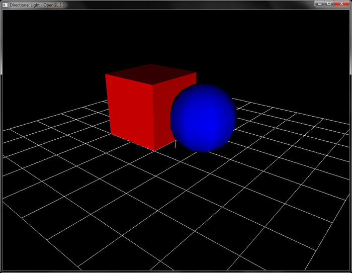
In this recipe, we will now implement directional light. The only difference between a point light and a directional light is that in the case of the directional light source, there is no position, however, there is direction, as shown in the following figure.

We will build on the geometry handling code from the per-fragment lighting recipe, but, instead of the pulsating cubes, we will now render a single cube with a sphere. The code for this recipe is contained in the Chapter4/DirectionalLight folder. The same code also works for per-vertex directional light.
Let us start the recipe by following these simple steps:
- Calculate the light direction in eye space and pass it as shader uniform. Note that the last component is
0since now we have a light direction vector.lightDirectionES = glm::vec3(MV*glm::vec4(lightDirectionOS,0));
- In the vertex shader, output the eye space normal.
#version 330 core layout(location=0) in vec3 vVertex; layout(location=1) in vec3 vNormal; uniform mat4 MVP; uniform mat3 N; smooth out vec3 vEyeSpaceNormal; void main() { vEyeSpaceNormal = N*vNormal; gl_Position = MVP*vec4(vVertex,1); } - In the fragment shader, compute the diffuse component by calculating the dot product between the light direction vector in eye space with the eye space normal, and multiply with the diffuse color to get the fragment color. Note that here, the light vector is independent of the eye space vertex position.
#version 330 core layout(location=0) out vec4 vFragColor; uniform vec3 light_direction; uniform vec3 diffuse_color; smooth in vec3 vEyeSpaceNormal; void main() { vec3 L = (light_direction); float diffuse = max(0, dot(vEyeSpaceNormal, L)); vFragColor = diffuse*vec4(diffuse_color,1); }
The only difference between this recipe and the previous one is that we now pass the light direction instead of the position to the fragment shader. The rest of the calculation remains unchanged. If we want to apply attenuation, we can add the relevant shader snippets from the previous recipe.
0 since now we have a light direction vector.lightDirectionES = glm::vec3(MV*glm::vec4(lightDirectionOS,0));
#version 330 core
layout(location=0) in vec3 vVertex;
layout(location=1) in vec3 vNormal;
uniform mat4 MVP;
uniform mat3 N;
smooth out vec3 vEyeSpaceNormal;
void main()
{
vEyeSpaceNormal = N*vNormal;
gl_Position = MVP*vec4(vVertex,1);
}#version 330 core
layout(location=0) out vec4 vFragColor;
uniform vec3 light_direction;
uniform vec3 diffuse_color;
smooth in vec3 vEyeSpaceNormal;
void main() {
vec3 L = (light_direction);
float diffuse = max(0, dot(vEyeSpaceNormal, L));
vFragColor = diffuse*vec4(diffuse_color,1);
}The only difference between this recipe and the previous one is that we now pass the light direction instead of the position to the fragment shader. The rest of the calculation remains unchanged. If we want to apply attenuation, we can add the relevant shader snippets from the previous recipe.
Implementing per-fragment point light is demonstrated by following these steps:
- From the vertex shader, output the eye space vertex position and normal.
#version 330 core layout(location=0) in vec3 vVertex; layout(location=1) in vec3 vNormal; uniform mat4 MVP; uniform mat4 MV; uniform mat3 N; smooth out vec3 vEyeSpaceNormal; smooth out vec3 vEyeSpacePosition; void main() { vEyeSpacePosition = (MV*vec4(vVertex,1)).xyz; vEyeSpaceNormal = N*vNormal; gl_Position = MVP*vec4(vVertex,1); } - In the fragment shader, calculate the light position in eye space, and then calculate the vector from the eye space vertex position to the eye space light position. Store the light distance before normalizing the light vector.
#version 330 core layout(location=0) out vec4 vFragColor; uniform vec3 light_position; //light position in object space uniform vec3 diffuse_color; uniform mat4 MV; smooth in vec3 vEyeSpaceNormal; smooth in vec3 vEyeSpacePosition; const float k0 = 1.0; //constant attenuation const float k1 = 0.0; //linear attenuation const float k2 = 0.0; //quadratic attenuation void main() { vec3 vEyeSpaceLightPosition = (MV*vec4(light_position,1)).xyz; vec3 L = (vEyeSpaceLightPosition-vEyeSpacePosition); float d = length(L); L = normalize(L); float diffuse = max(0, dot(vEyeSpaceNormal, L)); float attenuationAmount = 1.0/(k0 + (k1*d) + (k2*d*d)); diffuse *= attenuationAmount; vFragColor = diffuse*vec4(diffuse_color,1); } - Apply attenuation based on the distance from the light source to the diffuse component.
float attenuationAmount = 1.0/(k0 + (k1*d) + (k2*d*d)); diffuse *= attenuationAmount;
- Multiply the diffuse component to the diffuse color and set it as the fragment color.
vFragColor = diffuse*vec4(diffuse_color,1);
The recipe follows the Implementing per-fragment directional light recipe. In addition, it performs the attenuation calculation. The attenuation of light is calculated by using the following formula:
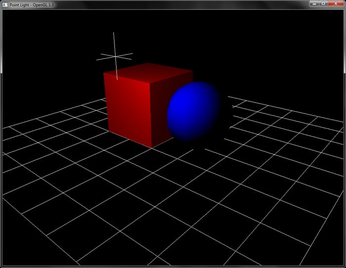
#version 330 core
layout(location=0) in vec3 vVertex;
layout(location=1) in vec3 vNormal;
uniform mat4 MVP;
uniform mat4 MV;
uniform mat3 N;
smooth out vec3 vEyeSpaceNormal;
smooth out vec3 vEyeSpacePosition;
void main() {
vEyeSpacePosition = (MV*vec4(vVertex,1)).xyz;
vEyeSpaceNormal = N*vNormal;
gl_Position = MVP*vec4(vVertex,1);
}- fragment shader, calculate the light position in eye space, and then calculate the vector from the eye space vertex position to the eye space light position. Store the light distance before normalizing the light vector.
#version 330 core layout(location=0) out vec4 vFragColor; uniform vec3 light_position; //light position in object space uniform vec3 diffuse_color; uniform mat4 MV; smooth in vec3 vEyeSpaceNormal; smooth in vec3 vEyeSpacePosition; const float k0 = 1.0; //constant attenuation const float k1 = 0.0; //linear attenuation const float k2 = 0.0; //quadratic attenuation void main() { vec3 vEyeSpaceLightPosition = (MV*vec4(light_position,1)).xyz; vec3 L = (vEyeSpaceLightPosition-vEyeSpacePosition); float d = length(L); L = normalize(L); float diffuse = max(0, dot(vEyeSpaceNormal, L)); float attenuationAmount = 1.0/(k0 + (k1*d) + (k2*d*d)); diffuse *= attenuationAmount; vFragColor = diffuse*vec4(diffuse_color,1); } - Apply attenuation based on the distance from the light source to the diffuse component.
float attenuationAmount = 1.0/(k0 + (k1*d) + (k2*d*d)); diffuse *= attenuationAmount;
- Multiply the diffuse component to the diffuse color and set it as the fragment color.
vFragColor = diffuse*vec4(diffuse_color,1);
The recipe follows the Implementing per-fragment directional light recipe. In addition, it performs the attenuation calculation. The attenuation of light is calculated by using the following formula:
follows the Implementing per-fragment directional light recipe. In addition, it performs the attenuation calculation. The attenuation of light is calculated by using the following formula:
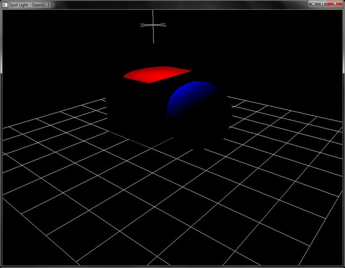
We will now implement per-fragment spot light. Spot light is a special point light that emits light in a directional cone. The size of this cone is determined by the spot cutoff amount, which is given in angles, as shown in the following figure. In addition, the sharpness of the spot is controlled by the parameter spot exponent. A higher value of the exponent gives a sharper falloff and vice versa.

The code for this recipe is contained in the Chapter4/SpotLight directory. The vertex shader is the same as in the point light recipe. The fragment shader calculates the diffuse component, as in the Implementing per-vertex and per-fragment point lighting recipe.
Let us start this recipe by following these simple steps:
- From the light's object space position and spot light target's position, calculate the spot light direction vector in eye space.
spotDirectionES = glm::normalize(glm::vec3(MV*glm::vec4(spotPositionOS-lightPosOS,0)))
- In the fragment shader, calculate the diffuse component as in point light. In addition, calculate the spot effect by finding the angle between the light direction and the spot direction vector.
vec3 L = (light_position.xyz-vEyeSpacePosition); float d = length(L); L = normalize(L); vec3 D = normalize(spot_direction); vec3 V = -L; float diffuse = 1; float spotEffect = dot(V,D);
- If the angle is greater than the spot cutoff, apply the spot exponent and then use the diffuse shader on the fragment.
if(spotEffect > spot_cutoff) { spotEffect = pow(spotEffect, spot_exponent); diffuse = max(0, dot(vEyeSpaceNormal, L)); float attenuationAmount = spotEffect/(k0 + (k1*d) + (k2*d*d)); diffuse *= attenuationAmount; vFragColor = diffuse*vec4(diffuse_color,1); }
The spot light is a special point light source that illuminates in a certain cone of direction. The amount of cone and the sharpness is controlled using the spot cutoff and spot exponent parameters respectively. Similar to the point light source, we first calculate the diffuse component. Instead of using the vector to light source (L) we use the opposite vector, which points in the direction of light (V=-L). Then we find out if the angle between the spot direction and the light direction vector is within the cutoff angle range. If it is, we apply the diffuse shading calculation. In addition, the sharpness of the spot light is controlled using the spot exponent parameter. This reduces the light in a falloff, giving a more pleasing spot light effect.
spotDirectionES = glm::normalize(glm::vec3(MV*glm::vec4(spotPositionOS-lightPosOS,0)))
vec3 L = (light_position.xyz-vEyeSpacePosition); float d = length(L); L = normalize(L); vec3 D = normalize(spot_direction); vec3 V = -L; float diffuse = 1; float spotEffect = dot(V,D);
if(spotEffect > spot_cutoff) {
spotEffect = pow(spotEffect, spot_exponent);
diffuse = max(0, dot(vEyeSpaceNormal, L));
float attenuationAmount = spotEffect/(k0 + (k1*d) + (k2*d*d));
diffuse *= attenuationAmount;
vFragColor = diffuse*vec4(diffuse_color,1);
}The spot light is a special point light source that illuminates in a certain cone of direction. The amount of cone and the sharpness is controlled using the spot cutoff and spot exponent parameters respectively. Similar to the point light source, we first calculate the diffuse component. Instead of using the vector to light source (L) we use the opposite vector, which points in the direction of light (V=-L). Then we find out if the angle between the spot direction and the light direction vector is within the cutoff angle range. If it is, we apply the diffuse shading calculation. In addition, the sharpness of the spot light is controlled using the spot exponent parameter. This reduces the light in a falloff, giving a more pleasing spot light effect.
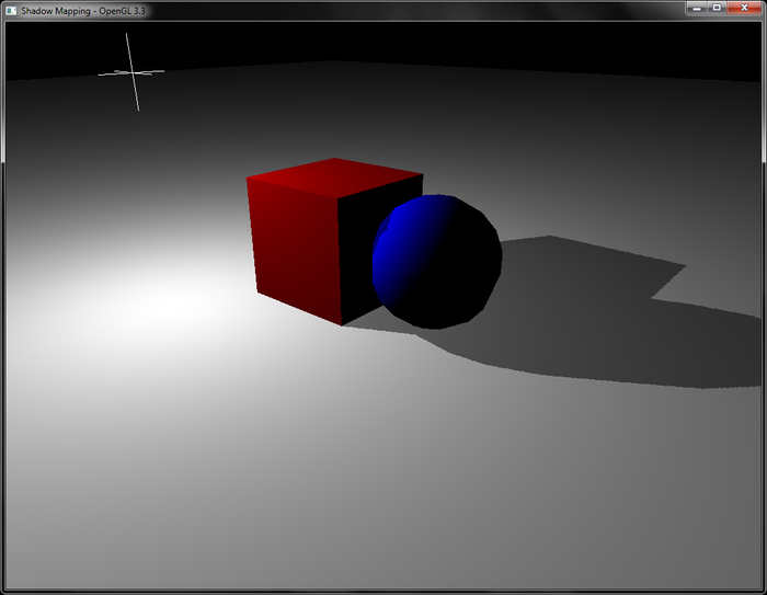
For this recipe, we will use the previous scene but instead of a grid object, we will use a plane object so that the generated shadows can be seen. The code for this recipe is contained in the Chapter4/ShadowMapping directory.
Let us start with this recipe by following these simple steps:
- Create an OpenGL texture object which will be our shadow map texture. Make sure to set the clamp mode to
GL_CLAMP_TO_BORDER, set the border color to{1,0,0,0}, give the texture comparison mode toGL_COMPARE_REF_TO_TEXTURE, and set the compare function toGL_LEQUAL. Set the texture internal format toGL_DEPTH_COMPONENT24.glGenTextures(1, &shadowMapTexID); glActiveTexture(GL_TEXTURE0); glBindTexture(GL_TEXTURE_2D, shadowMapTexID); GLfloat border[4]={1,0,0,0}; glTexParameteri(GL_TEXTURE_2D,GL_TEXTURE_MAG_FILTER,GL_NEAREST); glTexParameteri(GL_TEXTURE_2D,GL_TEXTURE_MIN_FILTER,GL_NEAREST); glTexParameteri(GL_TEXTURE_2D,GL_TEXTURE_WRAP_S,GL_CLAMP_TO_BORDER); glTexParameteri(GL_TEXTURE_2D,GL_TEXTURE_WRAP_T,GL_CLAMP_TO_BORDER); glTexParameteri(GL_TEXTURE_2D,GL_TEXTURE_COMPARE_MODE,GL_COMPARE_REF_TO_TEXTURE); glTexParameteri(GL_TEXTURE_2D,GL_TEXTURE_COMPARE_FUNC,GL_LEQUAL); glTexParameterfv(GL_TEXTURE_2D,GL_TEXTURE_BORDER_COLOR,border); glTexImage2D(GL_TEXTURE_2D,0,GL_DEPTH_COMPONENT24,SHADOWMAP_WIDTH,SHADOWMAP_HEIGHT,0,GL_DEPTH_COMPONENT,GL_UNSIGNED_BYTE,NULL); - Set up an FBO and use the shadow map texture as a single depth attachment. This will store the scene's depth from the point of view of light.
glGenFramebuffers(1,&fboID); glBindFramebuffer(GL_FRAMEBUFFER,fboID); glFramebufferTexture2D(GL_FRAMEBUFFER,GL_DEPTH_ATTACHMENT,GL_TEXTURE_2D,shadowMapTexID,0); GLenum status = glCheckFramebufferStatus(GL_FRAMEBUFFER); if(status == GL_FRAMEBUFFER_COMPLETE) { cout<<"FBO setup successful."<<endl; } else { cout<<"Problem in FBO setup."<<endl; } glBindFramebuffer(GL_FRAMEBUFFER,0); - Using the position and the direction of the light, set up the shadow matrix (
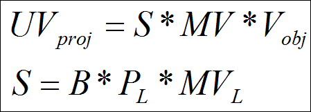
S) by combining the light modelview matrix (MV_L), projection matrix (P_L), and bias matrix (B). For reducing runtime calculation, we store the combined projection and bias matrix (BP) at initialization.MV_L = glm::lookAt(lightPosOS,glm::vec3(0,0,0), glm::vec3(0,1,0)); P_L = glm::perspective(50.0f,1.0f,1.0f, 25.0f); B = glm::scale(glm::translate(glm::mat4(1), glm::vec3(0.5,0.5,0.5)),glm::vec3(0.5,0.5,0.5)); BP = B*P_L; S = BP*MV_L;
- Bind the FBO and render the scene from the point of view of the light. Make sure to enable front-face culling (
glEnable(GL_CULL_FACE)andglCullFace(GL_FRONT)) so that the back-face depth values are rendered. Otherwise our objects will suffer from shadow acne. - Disable FBO, restore default viewport, and render the scene normally from the point of view of the camera.
glBindFramebuffer(GL_FRAMEBUFFER,0); glViewport(0,0,WIDTH, HEIGHT); DrawScene(MV, P, 0 );
- In the vertex shader, multiply the world space vertex positions (
M*vec4(vVertex,1)) with the shadow matrix (S) to obtain the shadow coordinates. These will be used for lookup of the depth values from theshadowmaptexture in the fragment shader.#version 330 core layout(location=0) in vec3 vVertex; layout(location=1) in vec3 vNormal; uniform mat4 MVP; //modelview projection matrix uniform mat4 MV; //modelview matrix uniform mat4 M; //model matrix uniform mat3 N; //normal matrix uniform mat4 S; //shadow matrix smooth out vec3 vEyeSpaceNormal; smooth out vec3 vEyeSpacePosition; smooth out vec4 vShadowCoords; void main() { vEyeSpacePosition = (MV*vec4(vVertex,1)).xyz; vEyeSpaceNormal = N*vNormal; vShadowCoords = S*(M*vec4(vVertex,1)); gl_Position = MVP*vec4(vVertex,1); } - In the fragment shader, use the shadow coordinates to lookup the depth value in the shadow map sampler which is of the
sampler2Dshadowtype. This sampler can be used with thetextureProjfunction to return a comparison outcome. We then use the comparison result to darken the diffuse component, simulating shadows.#version 330 core layout(location=0) out vec4 vFragColor; uniform sampler2DShadow shadowMap; uniform vec3 light_position; //light position in eye space uniform vec3 diffuse_color; smooth in vec3 vEyeSpaceNormal; smooth in vec3 vEyeSpacePosition; smooth in vec4 vShadowCoords; const float k0 = 1.0; //constant attenuation const float k1 = 0.0; //linear attenuation const float k2 = 0.0; //quadratic attenuation uniform bool bIsLightPass; //no shadows in light pass void main() { if(bIsLightPass) return; vec3 L = (light_position.xyz-vEyeSpacePosition); float d = length(L); L = normalize(L); float attenuationAmount = 1.0/(k0 + (k1*d) + (k2*d*d)); float diffuse = max(0, dot(vEyeSpaceNormal, L)) * attenuationAmount; if(vShadowCoords.w>1) { float shadow = textureProj(shadowMap, vShadowCoords); diffuse = mix(diffuse, diffuse*shadow, 0.5); } vFragColor = diffuse*vec4(diffuse_color, 1); }
The shadow mapping algorithm works in two passes. In the first pass, the scene is rendered from the point of view of light, and the depth buffer is stored into a texture called shadowmap. We use a single FBO with a depth attachment for this purpose. Apart from the conventional minification/magnification texture filtering, we set the texture wrapping mode to GL_CLAMP_TO_BORDER, which ensures that the values are clamped to the specified border color. Had we set this as GL_CLAMP or GL_CLAMP_TO_EDGE, the border pixels forming the shadow map would produce visible artefacts.
To render the scene from the point of view of light, the modelview matrix of the light (MV_L), the projection matrix (P_L), and the bias matrix (B) are calculated. After multiplying with the projection matrix, the coordinates are in clip space (that is, they range from [-1,-1,-1]). to [1,1,1]. The bias matrix rescales this range to bring the coordinates from [0,0,0] to [1,1,1] range so that the shadow lookup can be carried out.
The shadow map lookup computation is facilitated by the textureProj GLSL function. The result from the shadow map lookup returns 1 or 0. This result is multiplied with the shading computation. As it happens in the real world, we never have coal black shadows. Therefore, we combine the shadow outcome with the shading computation by using the mix GLSL function.
- Real-time Shadows, Elmar Eisemann, Michael Schwarz, Ulf Assarsson, Michael Wimmer, A K Peters/CRC Press
- OpenGL 4.0 Shading Language Cookbook, Chapter 7, Shadows, David Wolff, Packt Publishing
- ShadowMapping with GLSL by Fabien Sanglard: http://www.fabiensanglard.net/shadowmapping/index.php
will use the previous scene but instead of a grid object, we will use a plane object so that the generated shadows can be seen. The code for this recipe is contained in the Chapter4/ShadowMapping directory.
Let us start with this recipe by following these simple steps:
- Create an OpenGL texture object which will be our shadow map texture. Make sure to set the clamp mode to
GL_CLAMP_TO_BORDER, set the border color to{1,0,0,0}, give the texture comparison mode toGL_COMPARE_REF_TO_TEXTURE, and set the compare function toGL_LEQUAL. Set the texture internal format toGL_DEPTH_COMPONENT24.glGenTextures(1, &shadowMapTexID); glActiveTexture(GL_TEXTURE0); glBindTexture(GL_TEXTURE_2D, shadowMapTexID); GLfloat border[4]={1,0,0,0}; glTexParameteri(GL_TEXTURE_2D,GL_TEXTURE_MAG_FILTER,GL_NEAREST); glTexParameteri(GL_TEXTURE_2D,GL_TEXTURE_MIN_FILTER,GL_NEAREST); glTexParameteri(GL_TEXTURE_2D,GL_TEXTURE_WRAP_S,GL_CLAMP_TO_BORDER); glTexParameteri(GL_TEXTURE_2D,GL_TEXTURE_WRAP_T,GL_CLAMP_TO_BORDER); glTexParameteri(GL_TEXTURE_2D,GL_TEXTURE_COMPARE_MODE,GL_COMPARE_REF_TO_TEXTURE); glTexParameteri(GL_TEXTURE_2D,GL_TEXTURE_COMPARE_FUNC,GL_LEQUAL); glTexParameterfv(GL_TEXTURE_2D,GL_TEXTURE_BORDER_COLOR,border); glTexImage2D(GL_TEXTURE_2D,0,GL_DEPTH_COMPONENT24,SHADOWMAP_WIDTH,SHADOWMAP_HEIGHT,0,GL_DEPTH_COMPONENT,GL_UNSIGNED_BYTE,NULL); - Set up an FBO and use the shadow map texture as a single depth attachment. This will store the scene's depth from the point of view of light.
glGenFramebuffers(1,&fboID); glBindFramebuffer(GL_FRAMEBUFFER,fboID); glFramebufferTexture2D(GL_FRAMEBUFFER,GL_DEPTH_ATTACHMENT,GL_TEXTURE_2D,shadowMapTexID,0); GLenum status = glCheckFramebufferStatus(GL_FRAMEBUFFER); if(status == GL_FRAMEBUFFER_COMPLETE) { cout<<"FBO setup successful."<<endl; } else { cout<<"Problem in FBO setup."<<endl; } glBindFramebuffer(GL_FRAMEBUFFER,0); - Using the position and the direction of the light, set up the shadow matrix (
S) by combining the light modelview matrix (MV_L), projection matrix (P_L), and bias matrix (B). For reducing runtime calculation, we store the combined projection and bias matrix (BP) at initialization.MV_L = glm::lookAt(lightPosOS,glm::vec3(0,0,0), glm::vec3(0,1,0)); P_L = glm::perspective(50.0f,1.0f,1.0f, 25.0f); B = glm::scale(glm::translate(glm::mat4(1), glm::vec3(0.5,0.5,0.5)),glm::vec3(0.5,0.5,0.5)); BP = B*P_L; S = BP*MV_L;
- Bind the FBO and render the scene from the point of view of the light. Make sure to enable front-face culling (
glEnable(GL_CULL_FACE)andglCullFace(GL_FRONT)) so that the back-face depth values are rendered. Otherwise our objects will suffer from shadow acne. - Disable FBO, restore default viewport, and render the scene normally from the point of view of the camera.
glBindFramebuffer(GL_FRAMEBUFFER,0); glViewport(0,0,WIDTH, HEIGHT); DrawScene(MV, P, 0 );
- In the vertex shader, multiply the world space vertex positions (
M*vec4(vVertex,1)) with the shadow matrix (S) to obtain the shadow coordinates. These will be used for lookup of the depth values from theshadowmaptexture in the fragment shader.#version 330 core layout(location=0) in vec3 vVertex; layout(location=1) in vec3 vNormal; uniform mat4 MVP; //modelview projection matrix uniform mat4 MV; //modelview matrix uniform mat4 M; //model matrix uniform mat3 N; //normal matrix uniform mat4 S; //shadow matrix smooth out vec3 vEyeSpaceNormal; smooth out vec3 vEyeSpacePosition; smooth out vec4 vShadowCoords; void main() { vEyeSpacePosition = (MV*vec4(vVertex,1)).xyz; vEyeSpaceNormal = N*vNormal; vShadowCoords = S*(M*vec4(vVertex,1)); gl_Position = MVP*vec4(vVertex,1); } - In the fragment shader, use the shadow coordinates to lookup the depth value in the shadow map sampler which is of the
sampler2Dshadowtype. This sampler can be used with thetextureProjfunction to return a comparison outcome. We then use the comparison result to darken the diffuse component, simulating shadows.#version 330 core layout(location=0) out vec4 vFragColor; uniform sampler2DShadow shadowMap; uniform vec3 light_position; //light position in eye space uniform vec3 diffuse_color; smooth in vec3 vEyeSpaceNormal; smooth in vec3 vEyeSpacePosition; smooth in vec4 vShadowCoords; const float k0 = 1.0; //constant attenuation const float k1 = 0.0; //linear attenuation const float k2 = 0.0; //quadratic attenuation uniform bool bIsLightPass; //no shadows in light pass void main() { if(bIsLightPass) return; vec3 L = (light_position.xyz-vEyeSpacePosition); float d = length(L); L = normalize(L); float attenuationAmount = 1.0/(k0 + (k1*d) + (k2*d*d)); float diffuse = max(0, dot(vEyeSpaceNormal, L)) * attenuationAmount; if(vShadowCoords.w>1) { float shadow = textureProj(shadowMap, vShadowCoords); diffuse = mix(diffuse, diffuse*shadow, 0.5); } vFragColor = diffuse*vec4(diffuse_color, 1); }
The shadow mapping algorithm works in two passes. In the first pass, the scene is rendered from the point of view of light, and the depth buffer is stored into a texture called shadowmap. We use a single FBO with a depth attachment for this purpose. Apart from the conventional minification/magnification texture filtering, we set the texture wrapping mode to GL_CLAMP_TO_BORDER, which ensures that the values are clamped to the specified border color. Had we set this as GL_CLAMP or GL_CLAMP_TO_EDGE, the border pixels forming the shadow map would produce visible artefacts.
To render the scene from the point of view of light, the modelview matrix of the light (MV_L), the projection matrix (P_L), and the bias matrix (B) are calculated. After multiplying with the projection matrix, the coordinates are in clip space (that is, they range from [-1,-1,-1]). to [1,1,1]. The bias matrix rescales this range to bring the coordinates from [0,0,0] to [1,1,1] range so that the shadow lookup can be carried out.
The shadow map lookup computation is facilitated by the textureProj GLSL function. The result from the shadow map lookup returns 1 or 0. This result is multiplied with the shading computation. As it happens in the real world, we never have coal black shadows. Therefore, we combine the shadow outcome with the shading computation by using the mix GLSL function.
- Real-time Shadows, Elmar Eisemann, Michael Schwarz, Ulf Assarsson, Michael Wimmer, A K Peters/CRC Press
- OpenGL 4.0 Shading Language Cookbook, Chapter 7, Shadows, David Wolff, Packt Publishing
- ShadowMapping with GLSL by Fabien Sanglard: http://www.fabiensanglard.net/shadowmapping/index.php
GL_CLAMP_TO_BORDER, set the border color to {1,0,0,0}, give the texture comparison mode to GL_COMPARE_REF_TO_TEXTURE, and set the compare function to GL_LEQUAL. Set the texture internal format to GL_DEPTH_COMPONENT24.glGenTextures(1, &shadowMapTexID);
glActiveTexture(GL_TEXTURE0);
glBindTexture(GL_TEXTURE_2D, shadowMapTexID);
GLfloat border[4]={1,0,0,0};
glTexParameteri(GL_TEXTURE_2D,GL_TEXTURE_MAG_FILTER,GL_NEAREST);
glTexParameteri(GL_TEXTURE_2D,GL_TEXTURE_MIN_FILTER,GL_NEAREST);
glTexParameteri(GL_TEXTURE_2D,GL_TEXTURE_WRAP_S,GL_CLAMP_TO_BORDER);
glTexParameteri(GL_TEXTURE_2D,GL_TEXTURE_WRAP_T,GL_CLAMP_TO_BORDER);
glTexParameteri(GL_TEXTURE_2D,GL_TEXTURE_COMPARE_MODE,GL_COMPARE_REF_TO_TEXTURE);
glTexParameteri(GL_TEXTURE_2D,GL_TEXTURE_COMPARE_FUNC,GL_LEQUAL);
glTexParameterfv(GL_TEXTURE_2D,GL_TEXTURE_BORDER_COLOR,border);
glTexImage2D(GL_TEXTURE_2D,0,GL_DEPTH_COMPONENT24,SHADOWMAP_WIDTH,SHADOWMAP_HEIGHT,0,GL_DEPTH_COMPONENT,GL_UNSIGNED_BYTE,NULL);
glGenFramebuffers(1,&fboID);
glBindFramebuffer(GL_FRAMEBUFFER,fboID);
glFramebufferTexture2D(GL_FRAMEBUFFER,GL_DEPTH_ATTACHMENT,GL_TEXTURE_2D,shadowMapTexID,0);
GLenum status = glCheckFramebufferStatus(GL_FRAMEBUFFER);
if(status == GL_FRAMEBUFFER_COMPLETE) {
cout<<"FBO setup successful."<<endl;
} else {
cout<<"Problem in FBO setup."<<endl;
}
glBindFramebuffer(GL_FRAMEBUFFER,0);- position and the direction of the light, set up the shadow matrix (
S) by combining the light modelview matrix (MV_L), projection matrix (P_L), and bias matrix (B). For reducing runtime calculation, we store the combined projection and bias matrix (BP) at initialization.MV_L = glm::lookAt(lightPosOS,glm::vec3(0,0,0), glm::vec3(0,1,0)); P_L = glm::perspective(50.0f,1.0f,1.0f, 25.0f); B = glm::scale(glm::translate(glm::mat4(1), glm::vec3(0.5,0.5,0.5)),glm::vec3(0.5,0.5,0.5)); BP = B*P_L; S = BP*MV_L;
- Bind the FBO and render the scene from the point of view of the light. Make sure to enable front-face culling (
glEnable(GL_CULL_FACE)andglCullFace(GL_FRONT)) so that the back-face depth values are rendered. Otherwise our objects will suffer from shadow acne. - Disable FBO, restore default viewport, and render the scene normally from the point of view of the camera.
glBindFramebuffer(GL_FRAMEBUFFER,0); glViewport(0,0,WIDTH, HEIGHT); DrawScene(MV, P, 0 );
- In the vertex shader, multiply the world space vertex positions (
M*vec4(vVertex,1)) with the shadow matrix (S) to obtain the shadow coordinates. These will be used for lookup of the depth values from theshadowmaptexture in the fragment shader.#version 330 core layout(location=0) in vec3 vVertex; layout(location=1) in vec3 vNormal; uniform mat4 MVP; //modelview projection matrix uniform mat4 MV; //modelview matrix uniform mat4 M; //model matrix uniform mat3 N; //normal matrix uniform mat4 S; //shadow matrix smooth out vec3 vEyeSpaceNormal; smooth out vec3 vEyeSpacePosition; smooth out vec4 vShadowCoords; void main() { vEyeSpacePosition = (MV*vec4(vVertex,1)).xyz; vEyeSpaceNormal = N*vNormal; vShadowCoords = S*(M*vec4(vVertex,1)); gl_Position = MVP*vec4(vVertex,1); } - In the fragment shader, use the shadow coordinates to lookup the depth value in the shadow map sampler which is of the
sampler2Dshadowtype. This sampler can be used with thetextureProjfunction to return a comparison outcome. We then use the comparison result to darken the diffuse component, simulating shadows.#version 330 core layout(location=0) out vec4 vFragColor; uniform sampler2DShadow shadowMap; uniform vec3 light_position; //light position in eye space uniform vec3 diffuse_color; smooth in vec3 vEyeSpaceNormal; smooth in vec3 vEyeSpacePosition; smooth in vec4 vShadowCoords; const float k0 = 1.0; //constant attenuation const float k1 = 0.0; //linear attenuation const float k2 = 0.0; //quadratic attenuation uniform bool bIsLightPass; //no shadows in light pass void main() { if(bIsLightPass) return; vec3 L = (light_position.xyz-vEyeSpacePosition); float d = length(L); L = normalize(L); float attenuationAmount = 1.0/(k0 + (k1*d) + (k2*d*d)); float diffuse = max(0, dot(vEyeSpaceNormal, L)) * attenuationAmount; if(vShadowCoords.w>1) { float shadow = textureProj(shadowMap, vShadowCoords); diffuse = mix(diffuse, diffuse*shadow, 0.5); } vFragColor = diffuse*vec4(diffuse_color, 1); }
The shadow mapping algorithm works in two passes. In the first pass, the scene is rendered from the point of view of light, and the depth buffer is stored into a texture called shadowmap. We use a single FBO with a depth attachment for this purpose. Apart from the conventional minification/magnification texture filtering, we set the texture wrapping mode to GL_CLAMP_TO_BORDER, which ensures that the values are clamped to the specified border color. Had we set this as GL_CLAMP or GL_CLAMP_TO_EDGE, the border pixels forming the shadow map would produce visible artefacts.
To render the scene from the point of view of light, the modelview matrix of the light (MV_L), the projection matrix (P_L), and the bias matrix (B) are calculated. After multiplying with the projection matrix, the coordinates are in clip space (that is, they range from [-1,-1,-1]). to [1,1,1]. The bias matrix rescales this range to bring the coordinates from [0,0,0] to [1,1,1] range so that the shadow lookup can be carried out.
The shadow map lookup computation is facilitated by the textureProj GLSL function. The result from the shadow map lookup returns 1 or 0. This result is multiplied with the shading computation. As it happens in the real world, we never have coal black shadows. Therefore, we combine the shadow outcome with the shading computation by using the mix GLSL function.
- Real-time Shadows, Elmar Eisemann, Michael Schwarz, Ulf Assarsson, Michael Wimmer, A K Peters/CRC Press
- OpenGL 4.0 Shading Language Cookbook, Chapter 7, Shadows, David Wolff, Packt Publishing
- ShadowMapping with GLSL by Fabien Sanglard: http://www.fabiensanglard.net/shadowmapping/index.php
mapping algorithm works in two passes. In the first pass, the scene is rendered from the point of view of light, and the depth buffer is stored into a texture called shadowmap. We use a single FBO with a depth attachment for this purpose. Apart from the conventional minification/magnification texture filtering, we set the texture wrapping mode to GL_CLAMP_TO_BORDER, which ensures that the values are clamped to the specified border color. Had we set this as GL_CLAMP or GL_CLAMP_TO_EDGE, the border pixels forming the shadow map would produce visible artefacts.
To render the scene from the point of view of light, the modelview matrix of the light (MV_L), the projection matrix (P_L), and the bias matrix (B) are calculated. After multiplying with the projection matrix, the coordinates are in clip space (that is, they range from [-1,-1,-1]). to [1,1,1]. The bias matrix rescales this range to bring the coordinates from [0,0,0] to [1,1,1] range so that the shadow lookup can be carried out.
The shadow map lookup computation is facilitated by the textureProj GLSL function. The result from the shadow map lookup returns 1 or 0. This result is multiplied with the shading computation. As it happens in the real world, we never have coal black shadows. Therefore, we combine the shadow outcome with the shading computation by using the mix GLSL function.
- Real-time Shadows, Elmar Eisemann, Michael Schwarz, Ulf Assarsson, Michael Wimmer, A K Peters/CRC Press
- OpenGL 4.0 Shading Language Cookbook, Chapter 7, Shadows, David Wolff, Packt Publishing
- ShadowMapping with GLSL by Fabien Sanglard: http://www.fabiensanglard.net/shadowmapping/index.php
- Real-time Shadows, Elmar Eisemann, Michael Schwarz, Ulf Assarsson, Michael Wimmer, A K Peters/CRC Press
- OpenGL 4.0 Shading Language Cookbook, Chapter 7, Shadows, David Wolff, Packt Publishing
- ShadowMapping with GLSL by Fabien Sanglard: http://www.fabiensanglard.net/shadowmapping/index.php
- Chapter 7, Shadows, David Wolff, Packt Publishing
- ShadowMapping with GLSL by Fabien Sanglard: http://www.fabiensanglard.net/shadowmapping/index.php
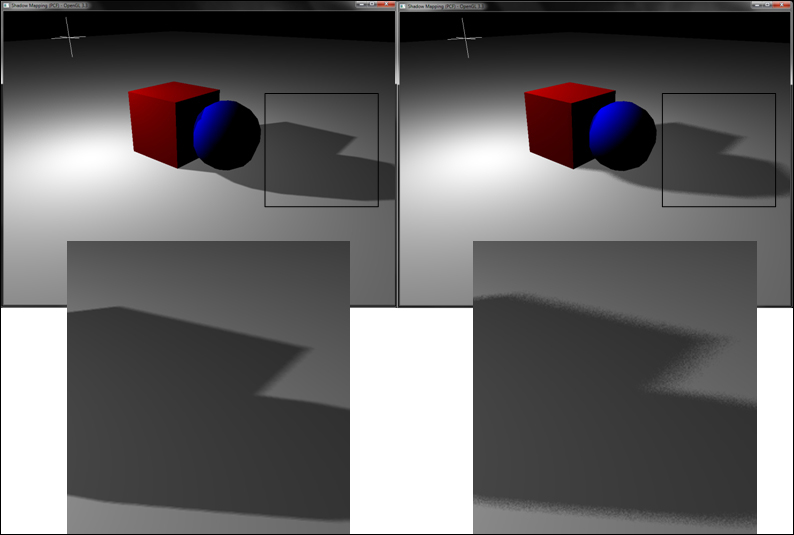
The shadow mapping algorithm, though simple to implement, suffers from aliasing artefacts, which are due to the shadowmap resolution. In addition, the shadows produced using this approach are hard. These can be minimized either by increasing the shadowmap resolution or taking more samples. The latter approach is called percentage closer filtering (PCF), where more samples are taken for the shadowmap lookup and the percentage of the samples is used to estimate if a fragment is in shadow. Thus, in PCF, instead of a single lookup, we sample an n×n neighborhood of shadowmap and then average the values.
The code for this recipe is contained in the Chapter4/ShadowMappingPCF directory. It builds on top of the previous recipe, Implementing shadow mapping with FBO. We use the same scene but augment it with PCF.
Let us see how to extend the basic shadow mapping with PCF.
- Change the
shadowmaptexture minification/magnification filtering modes toGL_LINEAR. Here, we exploit the texture filtering capabilities of the GPU to reduce aliasing artefacts during sampling of the shadow map. Even with the linear filtering support, we have to take additional samples to reduce the artefacts.glTexParameteri(GL_TEXTURE_2D,GL_TEXTURE_MAG_FILTER,GL_LINEAR); glTexParameteri(GL_TEXTURE_2D,GL_TEXTURE_MIN_FILTER,GL_LINEAR);
- In the fragment shader, instead of a single texture lookup as in the shadow map recipe, we use a number of samples. GLSL provides a convenient function,
textureProjOffset, to allow calculation of samples using an offset. For this recipe, we look at a 3×3 neighborhood around the current shadow map point. Hence, we use a large offset of 2. This helps to reduce sampling artefacts.if(vShadowCoords.w>1) { float sum = 0; sum += textureProjOffset(shadowMap,vShadowCoords,ivec2(-2,-2)); sum += textureProjOffset(shadowMap,vShadowCoords,ivec2(-2, 0)); sum += textureProjOffset(shadowMap,vShadowCoords,ivec2(-2, 2)); sum += textureProjOffset(shadowMap,vShadowCoords,ivec2( 0,-2)); sum += textureProjOffset(shadowMap,vShadowCoords,ivec2( 0, 0)); sum += textureProjOffset(shadowMap,vShadowCoords,ivec2( 0, 2)); sum += textureProjOffset(shadowMap,vShadowCoords,ivec2( 2,-2)); sum += textureProjOffset(shadowMap,vShadowCoords,ivec2( 2, 0)); sum += textureProjOffset(shadowMap,vShadowCoords,ivec2( 2, 2)); float shadow = sum/9.0; diffuse = mix(diffuse, diffuse*shadow, 0.5); }
In order to implement PCF, the first change we need is to set the texture filtering mode to linear filtering. This change enabled the GPU to bilinearly interpolate the shadow value. This gives smoother edges since the hardware does PCF filtering underneath. However it is not enough for our purpose. Therefore, we have to take additional samples to improve the result.
Then, the sampling for PCF uses the noise function to shift the shadow offset, as shown in the following shader code:

for this recipe is contained in the Chapter4/ShadowMappingPCF directory. It builds on top of the previous recipe, Implementing shadow mapping with FBO. We use the same scene but augment it with PCF.
Let us see how to extend the basic shadow mapping with PCF.
- Change the
shadowmaptexture minification/magnification filtering modes toGL_LINEAR. Here, we exploit the texture filtering capabilities of the GPU to reduce aliasing artefacts during sampling of the shadow map. Even with the linear filtering support, we have to take additional samples to reduce the artefacts.glTexParameteri(GL_TEXTURE_2D,GL_TEXTURE_MAG_FILTER,GL_LINEAR); glTexParameteri(GL_TEXTURE_2D,GL_TEXTURE_MIN_FILTER,GL_LINEAR);
- In the fragment shader, instead of a single texture lookup as in the shadow map recipe, we use a number of samples. GLSL provides a convenient function,
textureProjOffset, to allow calculation of samples using an offset. For this recipe, we look at a 3×3 neighborhood around the current shadow map point. Hence, we use a large offset of 2. This helps to reduce sampling artefacts.if(vShadowCoords.w>1) { float sum = 0; sum += textureProjOffset(shadowMap,vShadowCoords,ivec2(-2,-2)); sum += textureProjOffset(shadowMap,vShadowCoords,ivec2(-2, 0)); sum += textureProjOffset(shadowMap,vShadowCoords,ivec2(-2, 2)); sum += textureProjOffset(shadowMap,vShadowCoords,ivec2( 0,-2)); sum += textureProjOffset(shadowMap,vShadowCoords,ivec2( 0, 0)); sum += textureProjOffset(shadowMap,vShadowCoords,ivec2( 0, 2)); sum += textureProjOffset(shadowMap,vShadowCoords,ivec2( 2,-2)); sum += textureProjOffset(shadowMap,vShadowCoords,ivec2( 2, 0)); sum += textureProjOffset(shadowMap,vShadowCoords,ivec2( 2, 2)); float shadow = sum/9.0; diffuse = mix(diffuse, diffuse*shadow, 0.5); }
In order to implement PCF, the first change we need is to set the texture filtering mode to linear filtering. This change enabled the GPU to bilinearly interpolate the shadow value. This gives smoother edges since the hardware does PCF filtering underneath. However it is not enough for our purpose. Therefore, we have to take additional samples to improve the result.
Then, the sampling for PCF uses the noise function to shift the shadow offset, as shown in the following shader code:
shadowmap texture minification/magnification filtering modes to GL_LINEAR. Here, we exploit the texture filtering capabilities of the GPU to reduce aliasing artefacts during sampling of the shadow map. Even with the linear filtering support, we have to take additional samples to reduce the artefacts.glTexParameteri(GL_TEXTURE_2D,GL_TEXTURE_MAG_FILTER,GL_LINEAR); glTexParameteri(GL_TEXTURE_2D,GL_TEXTURE_MIN_FILTER,GL_LINEAR);
textureProjOffset, to allow calculation of samples using an offset. For this recipe, we look at a 3×3 neighborhood around the current shadow map point. Hence, we use a large offset of 2. This helps to reduce sampling artefacts.if(vShadowCoords.w>1) {
float sum = 0;
sum += textureProjOffset(shadowMap,vShadowCoords,ivec2(-2,-2));
sum += textureProjOffset(shadowMap,vShadowCoords,ivec2(-2, 0));
sum += textureProjOffset(shadowMap,vShadowCoords,ivec2(-2, 2));
sum += textureProjOffset(shadowMap,vShadowCoords,ivec2( 0,-2));
sum += textureProjOffset(shadowMap,vShadowCoords,ivec2( 0, 0));
sum += textureProjOffset(shadowMap,vShadowCoords,ivec2( 0, 2));
sum += textureProjOffset(shadowMap,vShadowCoords,ivec2( 2,-2));
sum += textureProjOffset(shadowMap,vShadowCoords,ivec2( 2, 0));
sum += textureProjOffset(shadowMap,vShadowCoords,ivec2( 2, 2));
float shadow = sum/9.0;
diffuse = mix(diffuse, diffuse*shadow, 0.5);
}In order to implement PCF, the first change we need is to set the texture filtering mode to linear filtering. This change enabled the GPU to bilinearly interpolate the shadow value. This gives smoother edges since the hardware does PCF filtering underneath. However it is not enough for our purpose. Therefore, we have to take additional samples to improve the result.
Then, the sampling for PCF uses the noise function to shift the shadow offset, as shown in the following shader code:
implement PCF, the first change we need is to set the texture filtering mode to linear filtering. This change enabled the GPU to bilinearly interpolate the shadow value. This gives smoother edges since the hardware does PCF filtering underneath. However it is not enough for our purpose. Therefore, we have to take additional samples to improve the result.
Then, the sampling for PCF uses the noise function to shift the shadow offset, as shown in the following shader code:

In this recipe, we will cover a technique which gives a much better result, has better performance, and at the same time is easier to calculate. The technique is called variance shadow mapping. In conventional PCF-filtered shadow mapping, we compare the depth value of the current fragment to the mean depth value in the shadow map, and based on the outcome, we shadow the fragment.
For this recipe, we will build on top of the shadow mapping recipe, Implementing shadow mapping with FBO. The code for this recipe is contained in the Chapter4/VarianceShadowMapping folder.
Let us start our recipe by following these simple steps:
- Set up the
shadowmaptexture as in the shadow map recipe, but this time remove the depth compare mode (glTexParameteri(GL_TEXTURE_2D,GL_TEXTURE_COMPARE_MODE,GL_COMPARE_REF_TO_TEXTURE)and glTexParameteri(GL_TEXTURE_2D,GL_TEXTURE_COMPARE_FUNC,GL_LEQUAL)).Also set the format of the texture to theGL_RGBA32Fformat. Also enable the mipmap generation for this texture. The mipmaps provide filtered textures across different scales and produces better alias-free shadows. We request five mipmap levels (by specifying the max level as 4).glGenTextures(1, &shadowMapTexID); glActiveTexture(GL_TEXTURE0); glBindTexture(GL_TEXTURE_2D, shadowMapTexID); glTexParameteri(GL_TEXTURE_2D,GL_TEXTURE_MAG_FILTER,GL_LINEAR; glTexParameteri(GL_TEXTURE_2D,GL_TEXTURE_MIN_FILTER,GL_LINEAR_MIPMAP_LINEAR); glTexParameteri(GL_TEXTURE_2D,GL_TEXTURE_WRAP_S,GL_CLAMP_TO_BORDER); glTexParameteri(GL_TEXTURE_2D,GL_TEXTURE_WRAP_T,GL_CLAMP_TO_BORDER); glTexParameterfv(GL_TEXTURE_2D,GL_TEXTURE_BORDER_COLOR,border; glTexImage2D(GL_TEXTURE_2D,0,GL_RGBA32F,SHADOWMAP_WIDTH,SHADOWMAP_HEIGHT,0,GL_RGBA,GL_FLOAT,NULL); glTexParameteri(GL_TEXTURE_2D, GL_TEXTURE_BASE_LEVEL, 0); glTexParameteri(GL_TEXTURE_2D, GL_TEXTURE_MAX_LEVEL, 4); glGenerateMipmap(GL_TEXTURE_2D);
- Set up two FBOs: one for shadowmap generation and another for shadowmap filtering. The shadowmap FBO has a
renderbufferattached to it for depth testing. The filtering FBO does not have arenderbufferattached to it but it has two texture attachments.glGenFramebuffers(1,&fboID); glGenRenderbuffers(1, &rboID); glBindFramebuffer(GL_FRAMEBUFFER,fboID); glBindRenderbuffer(GL_RENDERBUFFER, rboID); glRenderbufferStorage(GL_RENDERBUFFER, GL_DEPTH_COMPONENT32, SHADOWMAP_WIDTH, SHADOWMAP_HEIGHT); glFramebufferTexture2D(GL_FRAMEBUFFER,GL_COLOR_ATTACHMENT0,GL_TEXTURE_2D,shadowMapTexID,0); glFramebufferRenderbuffer(GL_FRAMEBUFFER, GL_DEPTH_ATTACHMENT, GL_RENDERBUFFER, rboID); GLenum status = glCheckFramebufferStatus(GL_FRAMEBUFFER); if(status == GL_FRAMEBUFFER_COMPLETE) { cout<<"FBO setup successful."<<endl; } else { cout<<"Problem in FBO setup."<<endl; } glBindFramebuffer(GL_FRAMEBUFFER,0); glGenFramebuffers(1,&filterFBOID); glBindFramebuffer(GL_FRAMEBUFFER,filterFBOID); glGenTextures(2, blurTexID); for(int i=0;i<2;i++) { glActiveTexture(GL_TEXTURE1+i); glBindTexture(GL_TEXTURE_2D, blurTexID[i]); glTexParameteri(GL_TEXTURE_2D,GL_TEXTURE_MAG_FILTER,GL_LINEAR); glTexParameteri(GL_TEXTURE_2D,GL_TEXTURE_MIN_FILTER,GL_LINEAR); glTexParameteri(GL_TEXTURE_2D,GL_TEXTURE_WRAP_S,GL_CLAMP_TO_BORDER); glTexParameteri(GL_TEXTURE_2D,GL_TEXTURE_WRAP_T,GL_CLAMP_TO_BORDER); glTexParameterfv(GL_TEXTURE_2D,GL_TEXTURE_BORDER_COLOR,border); glTexImage2D(GL_TEXTURE_2D,0,GL_RGBA32F,SHADOWMAP_WIDTH,SHADOWMAP_HEIGHT,0,GL_RGBA,GL_FLOAT,NULL); glFramebufferTexture2D(GL_FRAMEBUFFER,GL_COLOR_ATTACHMENT0+i, GL_TEXTURE_2D,blurTexID[i],0); } status = glCheckFramebufferStatus(GL_FRAMEBUFFER); if(status == GL_FRAMEBUFFER_COMPLETE) { cout<<"Filtering FBO setup successful."<<endl; } else { cout<<"Problem in Filtering FBO setup."<<endl; } glBindFramebuffer(GL_FRAMEBUFFER,0);
- Bind the
shadowmapFBO, set the viewport to the size of theshadowmaptexture, and render the scene from the point of view of the light, as in the Implementing shadow mapping with FBO recipe. In this pass, instead of storing the depth as in the shadow mapping recipe, we use a custom fragment shader (Chapter4/VarianceShadowmapping/shaders/firststep.frag) to output the depth and depth*depth values in the red and green channels of the fragment output color.glBindFramebuffer(GL_FRAMEBUFFER,fboID); glViewport(0,0,SHADOWMAP_WIDTH, SHADOWMAP_HEIGHT); glDrawBuffer(GL_COLOR_ATTACHMENT0); glClear(GL_COLOR_BUFFER_BIT|GL_DEPTH_BUFFER_BIT); DrawSceneFirstPass(MV_L, P_L);
The shader code is as follows:
#version 330 core layout(location=0) out vec4 vFragColor; smooth in vec4 clipSpacePos; void main() { vec3 pos = clipSpacePos.xyz/clipSpacePos.w; //-1 to 1 pos.z += 0.001; //add some offset to remove the shadow acne float depth = (pos.z +1)*0.5; // 0 to 1 float moment1 = depth; float moment2 = depth * depth; vFragColor = vec4(moment1,moment2,0,0); } - Bind the filtering FBO to filter the
shadowmaptexture generated in the first pass using separable Gaussian smoothing filters, which are more efficient and offer better performance. We first attach the vertical smoothing fragment shader (Chapter4/VarianceShadowmapping/shaders/GaussV.frag) to filter theshadowmaptexture and then the horizontal smoothing fragment shader (Chapter4/VarianceShadowmapping/shaders/GaussH.frag) to smooth the output from the vertical Gaussian smoothing filter.glBindFramebuffer(GL_FRAMEBUFFER,filterFBOID); glDrawBuffer(GL_COLOR_ATTACHMENT0); glBindVertexArray(quadVAOID); gaussianV_shader.Use(); glDrawElements(GL_TRIANGLES, 6, GL_UNSIGNED_SHORT, 0); glDrawBuffer(GL_COLOR_ATTACHMENT1); gaussianH_shader.Use(); glDrawElements(GL_TRIANGLES, 6, GL_UNSIGNED_SHORT, 0); glBindFramebuffer(GL_FRAMEBUFFER,0);
The horizontal Gaussian blur shader is as follows:
#version 330 core layout(location=0) out vec4 vFragColor; smooth in vec2 vUV; uniform sampler2D textureMap; const float kernel[]=float[21] (0.000272337, 0.00089296, 0.002583865, 0.00659813, 0.014869116, 0.029570767, 0.051898313, 0.080381679, 0.109868729, 0.132526984, 0.14107424, 0.132526984, 0.109868729, 0.080381679, 0.051898313, 0.029570767, 0.014869116, 0.00659813, 0.002583865, 0.00089296, 0.000272337); void main() { vec2 delta = 1.0/textureSize(textureMap,0); vec4 color = vec4(0); int index = 20; for(int i=-10;i<=10;i++) { color += kernel[index--]*texture(textureMap, vUV + (vec2(i*delta.x,0))); } vFragColor = vec4(color.xy,0,0); }In the vertical Gaussian shader, the loop statement is modified, whereas the rest of the shader is the same.
color += kernel[index--]*texture(textureMap, vUV + (vec2(0,i*delta.y)));
- Unbind the FBO, reset the default viewport, and then render the scene normally, as in the shadow mapping recipe.
glDrawBuffer(GL_BACK_LEFT); glViewport(0,0,WIDTH, HEIGHT); DrawScene(MV, P);
The variance shadowmap technique tries to represent the depth data such that it can be filtered linearly. Instead of storing the depth, it stores the depth and depth*depth value in a floating point texture, which is then filtered to reconstruct the first and second moments of the depth distribution. Using the moments, it estimates the variance in the filtering neighborhood. This helps in finding the probability of a fragment at a specific depth to be occluded using Chebyshev's inequality. For more mathematical details, we refer the reader to the See also section of this recipe.
After the first pass, the shadowmap texture is blurred using a separable Gaussian smoothing filter. First the vertical and then the horizontal filter is applied to the shadowmap texture by applying the shadowmap texture to a full-screen quad and alternating the filter FBO's color attachment. Note that the shadowmap texture is bound to texture unit 0 whereas the textures used for filtering are bound to texture unit 1 (attached to GL_COLOR_ATTTACHMENT0 on the filtering FBO) and texture unit 2 (attached to GL_COLOR_ATTACHMENT1 on the filtering FBO).
In the second pass, the scene is rendered from the point of view of the camera. The blurred shadowmap is used in the second pass as a texture to lookup the sample value (see Chapter4/VarianceShadowmapping/shaders/VarianceShadowMap.{vert, frag}). The variance shadow mapping vertex shader outputs the shadow texture coordinates, as in the shadow mapping recipe.
The texture coordinates after homogeneous division are used to lookup the shadow map storing the two moments. The two moments are used to estimate the variance. The variance is clamped and then the occlusion probability is estimated. The diffuse component is then modulated based on the obtained occlusion probability.
To recap, here is the complete variance shadow mapping fragment shader:
Variance shadow mapping is an interesting idea. However, it does suffer from light bleeding artefacts. There have been several improvements to the basic technique, such as summed area variance shadow maps, layered variance shadow maps, and more recently, sample distribution shadow maps, that are referred to in the See also section of this recipe. After getting a practical insight into the basic variance shadow mapping idea, we invite the reader to try and implement the different variants of this algorithm, as detailed in the references in the See also section.

- Proceedings of the 2006 symposium on Interactive 3D graphics and games, Variance Shadow Maps, pages 161-165 William Donnelly, Andrew Lauritzen
- GPU Gems 3, Chapter 8, Summed-Area Variance Shadow Maps, Andrew Lauritzen: http://http.developer.nvidia.com/GPUGems3/gpugems3_ch08.html
- Proceedings of the Graphics Interface 2008, Layered variance shadow maps, pages 139-146, Andrew Lauritzen, Michael McCool
- Sample Distribution Shadow Maps, ACM SIGGRAPH Symposium on Interactive 3D Graphics and Games (I3D) 2011, February, Andrew Lauritzen, Marco Salvi, and Aaron Lefohn
Let us start our recipe by following these simple steps:
- Set up the
shadowmaptexture as in the shadow map recipe, but this time remove the depth compare mode (glTexParameteri(GL_TEXTURE_2D,GL_TEXTURE_COMPARE_MODE,GL_COMPARE_REF_TO_TEXTURE)and glTexParameteri(GL_TEXTURE_2D,GL_TEXTURE_COMPARE_FUNC,GL_LEQUAL)).Also set the format of the texture to theGL_RGBA32Fformat. Also enable the mipmap generation for this texture. The mipmaps provide filtered textures across different scales and produces better alias-free shadows. We request five mipmap levels (by specifying the max level as 4).glGenTextures(1, &shadowMapTexID); glActiveTexture(GL_TEXTURE0); glBindTexture(GL_TEXTURE_2D, shadowMapTexID); glTexParameteri(GL_TEXTURE_2D,GL_TEXTURE_MAG_FILTER,GL_LINEAR; glTexParameteri(GL_TEXTURE_2D,GL_TEXTURE_MIN_FILTER,GL_LINEAR_MIPMAP_LINEAR); glTexParameteri(GL_TEXTURE_2D,GL_TEXTURE_WRAP_S,GL_CLAMP_TO_BORDER); glTexParameteri(GL_TEXTURE_2D,GL_TEXTURE_WRAP_T,GL_CLAMP_TO_BORDER); glTexParameterfv(GL_TEXTURE_2D,GL_TEXTURE_BORDER_COLOR,border; glTexImage2D(GL_TEXTURE_2D,0,GL_RGBA32F,SHADOWMAP_WIDTH,SHADOWMAP_HEIGHT,0,GL_RGBA,GL_FLOAT,NULL); glTexParameteri(GL_TEXTURE_2D, GL_TEXTURE_BASE_LEVEL, 0); glTexParameteri(GL_TEXTURE_2D, GL_TEXTURE_MAX_LEVEL, 4); glGenerateMipmap(GL_TEXTURE_2D);
- Set up two FBOs: one for shadowmap generation and another for shadowmap filtering. The shadowmap FBO has a
renderbufferattached to it for depth testing. The filtering FBO does not have arenderbufferattached to it but it has two texture attachments.glGenFramebuffers(1,&fboID); glGenRenderbuffers(1, &rboID); glBindFramebuffer(GL_FRAMEBUFFER,fboID); glBindRenderbuffer(GL_RENDERBUFFER, rboID); glRenderbufferStorage(GL_RENDERBUFFER, GL_DEPTH_COMPONENT32, SHADOWMAP_WIDTH, SHADOWMAP_HEIGHT); glFramebufferTexture2D(GL_FRAMEBUFFER,GL_COLOR_ATTACHMENT0,GL_TEXTURE_2D,shadowMapTexID,0); glFramebufferRenderbuffer(GL_FRAMEBUFFER, GL_DEPTH_ATTACHMENT, GL_RENDERBUFFER, rboID); GLenum status = glCheckFramebufferStatus(GL_FRAMEBUFFER); if(status == GL_FRAMEBUFFER_COMPLETE) { cout<<"FBO setup successful."<<endl; } else { cout<<"Problem in FBO setup."<<endl; } glBindFramebuffer(GL_FRAMEBUFFER,0); glGenFramebuffers(1,&filterFBOID); glBindFramebuffer(GL_FRAMEBUFFER,filterFBOID); glGenTextures(2, blurTexID); for(int i=0;i<2;i++) { glActiveTexture(GL_TEXTURE1+i); glBindTexture(GL_TEXTURE_2D, blurTexID[i]); glTexParameteri(GL_TEXTURE_2D,GL_TEXTURE_MAG_FILTER,GL_LINEAR); glTexParameteri(GL_TEXTURE_2D,GL_TEXTURE_MIN_FILTER,GL_LINEAR); glTexParameteri(GL_TEXTURE_2D,GL_TEXTURE_WRAP_S,GL_CLAMP_TO_BORDER); glTexParameteri(GL_TEXTURE_2D,GL_TEXTURE_WRAP_T,GL_CLAMP_TO_BORDER); glTexParameterfv(GL_TEXTURE_2D,GL_TEXTURE_BORDER_COLOR,border); glTexImage2D(GL_TEXTURE_2D,0,GL_RGBA32F,SHADOWMAP_WIDTH,SHADOWMAP_HEIGHT,0,GL_RGBA,GL_FLOAT,NULL); glFramebufferTexture2D(GL_FRAMEBUFFER,GL_COLOR_ATTACHMENT0+i, GL_TEXTURE_2D,blurTexID[i],0); } status = glCheckFramebufferStatus(GL_FRAMEBUFFER); if(status == GL_FRAMEBUFFER_COMPLETE) { cout<<"Filtering FBO setup successful."<<endl; } else { cout<<"Problem in Filtering FBO setup."<<endl; } glBindFramebuffer(GL_FRAMEBUFFER,0);
- Bind the
shadowmapFBO, set the viewport to the size of theshadowmaptexture, and render the scene from the point of view of the light, as in the Implementing shadow mapping with FBO recipe. In this pass, instead of storing the depth as in the shadow mapping recipe, we use a custom fragment shader (Chapter4/VarianceShadowmapping/shaders/firststep.frag) to output the depth and depth*depth values in the red and green channels of the fragment output color.glBindFramebuffer(GL_FRAMEBUFFER,fboID); glViewport(0,0,SHADOWMAP_WIDTH, SHADOWMAP_HEIGHT); glDrawBuffer(GL_COLOR_ATTACHMENT0); glClear(GL_COLOR_BUFFER_BIT|GL_DEPTH_BUFFER_BIT); DrawSceneFirstPass(MV_L, P_L);
The shader code is as follows:
#version 330 core layout(location=0) out vec4 vFragColor; smooth in vec4 clipSpacePos; void main() { vec3 pos = clipSpacePos.xyz/clipSpacePos.w; //-1 to 1 pos.z += 0.001; //add some offset to remove the shadow acne float depth = (pos.z +1)*0.5; // 0 to 1 float moment1 = depth; float moment2 = depth * depth; vFragColor = vec4(moment1,moment2,0,0); } - Bind the filtering FBO to filter the
shadowmaptexture generated in the first pass using separable Gaussian smoothing filters, which are more efficient and offer better performance. We first attach the vertical smoothing fragment shader (Chapter4/VarianceShadowmapping/shaders/GaussV.frag) to filter theshadowmaptexture and then the horizontal smoothing fragment shader (Chapter4/VarianceShadowmapping/shaders/GaussH.frag) to smooth the output from the vertical Gaussian smoothing filter.glBindFramebuffer(GL_FRAMEBUFFER,filterFBOID); glDrawBuffer(GL_COLOR_ATTACHMENT0); glBindVertexArray(quadVAOID); gaussianV_shader.Use(); glDrawElements(GL_TRIANGLES, 6, GL_UNSIGNED_SHORT, 0); glDrawBuffer(GL_COLOR_ATTACHMENT1); gaussianH_shader.Use(); glDrawElements(GL_TRIANGLES, 6, GL_UNSIGNED_SHORT, 0); glBindFramebuffer(GL_FRAMEBUFFER,0);
The horizontal Gaussian blur shader is as follows:
#version 330 core layout(location=0) out vec4 vFragColor; smooth in vec2 vUV; uniform sampler2D textureMap; const float kernel[]=float[21] (0.000272337, 0.00089296, 0.002583865, 0.00659813, 0.014869116, 0.029570767, 0.051898313, 0.080381679, 0.109868729, 0.132526984, 0.14107424, 0.132526984, 0.109868729, 0.080381679, 0.051898313, 0.029570767, 0.014869116, 0.00659813, 0.002583865, 0.00089296, 0.000272337); void main() { vec2 delta = 1.0/textureSize(textureMap,0); vec4 color = vec4(0); int index = 20; for(int i=-10;i<=10;i++) { color += kernel[index--]*texture(textureMap, vUV + (vec2(i*delta.x,0))); } vFragColor = vec4(color.xy,0,0); }In the vertical Gaussian shader, the loop statement is modified, whereas the rest of the shader is the same.
color += kernel[index--]*texture(textureMap, vUV + (vec2(0,i*delta.y)));
- Unbind the FBO, reset the default viewport, and then render the scene normally, as in the shadow mapping recipe.
glDrawBuffer(GL_BACK_LEFT); glViewport(0,0,WIDTH, HEIGHT); DrawScene(MV, P);
The variance shadowmap technique tries to represent the depth data such that it can be filtered linearly. Instead of storing the depth, it stores the depth and depth*depth value in a floating point texture, which is then filtered to reconstruct the first and second moments of the depth distribution. Using the moments, it estimates the variance in the filtering neighborhood. This helps in finding the probability of a fragment at a specific depth to be occluded using Chebyshev's inequality. For more mathematical details, we refer the reader to the See also section of this recipe.
After the first pass, the shadowmap texture is blurred using a separable Gaussian smoothing filter. First the vertical and then the horizontal filter is applied to the shadowmap texture by applying the shadowmap texture to a full-screen quad and alternating the filter FBO's color attachment. Note that the shadowmap texture is bound to texture unit 0 whereas the textures used for filtering are bound to texture unit 1 (attached to GL_COLOR_ATTTACHMENT0 on the filtering FBO) and texture unit 2 (attached to GL_COLOR_ATTACHMENT1 on the filtering FBO).
In the second pass, the scene is rendered from the point of view of the camera. The blurred shadowmap is used in the second pass as a texture to lookup the sample value (see Chapter4/VarianceShadowmapping/shaders/VarianceShadowMap.{vert, frag}). The variance shadow mapping vertex shader outputs the shadow texture coordinates, as in the shadow mapping recipe.
The texture coordinates after homogeneous division are used to lookup the shadow map storing the two moments. The two moments are used to estimate the variance. The variance is clamped and then the occlusion probability is estimated. The diffuse component is then modulated based on the obtained occlusion probability.
To recap, here is the complete variance shadow mapping fragment shader:
Variance shadow mapping is an interesting idea. However, it does suffer from light bleeding artefacts. There have been several improvements to the basic technique, such as summed area variance shadow maps, layered variance shadow maps, and more recently, sample distribution shadow maps, that are referred to in the See also section of this recipe. After getting a practical insight into the basic variance shadow mapping idea, we invite the reader to try and implement the different variants of this algorithm, as detailed in the references in the See also section.
- Proceedings of the 2006 symposium on Interactive 3D graphics and games, Variance Shadow Maps, pages 161-165 William Donnelly, Andrew Lauritzen
- GPU Gems 3, Chapter 8, Summed-Area Variance Shadow Maps, Andrew Lauritzen: http://http.developer.nvidia.com/GPUGems3/gpugems3_ch08.html
- Proceedings of the Graphics Interface 2008, Layered variance shadow maps, pages 139-146, Andrew Lauritzen, Michael McCool
- Sample Distribution Shadow Maps, ACM SIGGRAPH Symposium on Interactive 3D Graphics and Games (I3D) 2011, February, Andrew Lauritzen, Marco Salvi, and Aaron Lefohn
shadowmap texture as in the shadow map recipe, but this time remove the depth compare mode (glTexParameteri(GL_TEXTURE_2D,GL_TEXTURE_COMPARE_MODE,GL_COMPARE_REF_TO_TEXTURE) and glTexParameteri(GL_TEXTURE_2D,GL_TEXTURE_COMPARE_FUNC,GL_LEQUAL)). Also set the format of the texture to the GL_RGBA32F format. Also enable the mipmap generation for this texture. The mipmaps provide filtered textures across different scales and produces better alias-free shadows. We request five mipmap levels (by specifying the max level as 4).glGenTextures(1, &shadowMapTexID); glActiveTexture(GL_TEXTURE0); glBindTexture(GL_TEXTURE_2D, shadowMapTexID); glTexParameteri(GL_TEXTURE_2D,GL_TEXTURE_MAG_FILTER,GL_LINEAR; glTexParameteri(GL_TEXTURE_2D,GL_TEXTURE_MIN_FILTER,GL_LINEAR_MIPMAP_LINEAR); glTexParameteri(GL_TEXTURE_2D,GL_TEXTURE_WRAP_S,GL_CLAMP_TO_BORDER); glTexParameteri(GL_TEXTURE_2D,GL_TEXTURE_WRAP_T,GL_CLAMP_TO_BORDER); glTexParameterfv(GL_TEXTURE_2D,GL_TEXTURE_BORDER_COLOR,border; glTexImage2D(GL_TEXTURE_2D,0,GL_RGBA32F,SHADOWMAP_WIDTH,SHADOWMAP_HEIGHT,0,GL_RGBA,GL_FLOAT,NULL); glTexParameteri(GL_TEXTURE_2D, GL_TEXTURE_BASE_LEVEL, 0); glTexParameteri(GL_TEXTURE_2D, GL_TEXTURE_MAX_LEVEL, 4); glGenerateMipmap(GL_TEXTURE_2D);
- FBOs: one for shadowmap generation and another for shadowmap filtering. The shadowmap FBO has a
renderbufferattached to it for depth testing. The filtering FBO does not have arenderbufferattached to it but it has two texture attachments.glGenFramebuffers(1,&fboID); glGenRenderbuffers(1, &rboID); glBindFramebuffer(GL_FRAMEBUFFER,fboID); glBindRenderbuffer(GL_RENDERBUFFER, rboID); glRenderbufferStorage(GL_RENDERBUFFER, GL_DEPTH_COMPONENT32, SHADOWMAP_WIDTH, SHADOWMAP_HEIGHT); glFramebufferTexture2D(GL_FRAMEBUFFER,GL_COLOR_ATTACHMENT0,GL_TEXTURE_2D,shadowMapTexID,0); glFramebufferRenderbuffer(GL_FRAMEBUFFER, GL_DEPTH_ATTACHMENT, GL_RENDERBUFFER, rboID); GLenum status = glCheckFramebufferStatus(GL_FRAMEBUFFER); if(status == GL_FRAMEBUFFER_COMPLETE) { cout<<"FBO setup successful."<<endl; } else { cout<<"Problem in FBO setup."<<endl; } glBindFramebuffer(GL_FRAMEBUFFER,0); glGenFramebuffers(1,&filterFBOID); glBindFramebuffer(GL_FRAMEBUFFER,filterFBOID); glGenTextures(2, blurTexID); for(int i=0;i<2;i++) { glActiveTexture(GL_TEXTURE1+i); glBindTexture(GL_TEXTURE_2D, blurTexID[i]); glTexParameteri(GL_TEXTURE_2D,GL_TEXTURE_MAG_FILTER,GL_LINEAR); glTexParameteri(GL_TEXTURE_2D,GL_TEXTURE_MIN_FILTER,GL_LINEAR); glTexParameteri(GL_TEXTURE_2D,GL_TEXTURE_WRAP_S,GL_CLAMP_TO_BORDER); glTexParameteri(GL_TEXTURE_2D,GL_TEXTURE_WRAP_T,GL_CLAMP_TO_BORDER); glTexParameterfv(GL_TEXTURE_2D,GL_TEXTURE_BORDER_COLOR,border); glTexImage2D(GL_TEXTURE_2D,0,GL_RGBA32F,SHADOWMAP_WIDTH,SHADOWMAP_HEIGHT,0,GL_RGBA,GL_FLOAT,NULL); glFramebufferTexture2D(GL_FRAMEBUFFER,GL_COLOR_ATTACHMENT0+i, GL_TEXTURE_2D,blurTexID[i],0); } status = glCheckFramebufferStatus(GL_FRAMEBUFFER); if(status == GL_FRAMEBUFFER_COMPLETE) { cout<<"Filtering FBO setup successful."<<endl; } else { cout<<"Problem in Filtering FBO setup."<<endl; } glBindFramebuffer(GL_FRAMEBUFFER,0);
- Bind the
shadowmapFBO, set the viewport to the size of theshadowmaptexture, and render the scene from the point of view of the light, as in the Implementing shadow mapping with FBO recipe. In this pass, instead of storing the depth as in the shadow mapping recipe, we use a custom fragment shader (Chapter4/VarianceShadowmapping/shaders/firststep.frag) to output the depth and depth*depth values in the red and green channels of the fragment output color.glBindFramebuffer(GL_FRAMEBUFFER,fboID); glViewport(0,0,SHADOWMAP_WIDTH, SHADOWMAP_HEIGHT); glDrawBuffer(GL_COLOR_ATTACHMENT0); glClear(GL_COLOR_BUFFER_BIT|GL_DEPTH_BUFFER_BIT); DrawSceneFirstPass(MV_L, P_L);
The shader code is as follows:
#version 330 core layout(location=0) out vec4 vFragColor; smooth in vec4 clipSpacePos; void main() { vec3 pos = clipSpacePos.xyz/clipSpacePos.w; //-1 to 1 pos.z += 0.001; //add some offset to remove the shadow acne float depth = (pos.z +1)*0.5; // 0 to 1 float moment1 = depth; float moment2 = depth * depth; vFragColor = vec4(moment1,moment2,0,0); } - Bind the filtering FBO to filter the
shadowmaptexture generated in the first pass using separable Gaussian smoothing filters, which are more efficient and offer better performance. We first attach the vertical smoothing fragment shader (Chapter4/VarianceShadowmapping/shaders/GaussV.frag) to filter theshadowmaptexture and then the horizontal smoothing fragment shader (Chapter4/VarianceShadowmapping/shaders/GaussH.frag) to smooth the output from the vertical Gaussian smoothing filter.glBindFramebuffer(GL_FRAMEBUFFER,filterFBOID); glDrawBuffer(GL_COLOR_ATTACHMENT0); glBindVertexArray(quadVAOID); gaussianV_shader.Use(); glDrawElements(GL_TRIANGLES, 6, GL_UNSIGNED_SHORT, 0); glDrawBuffer(GL_COLOR_ATTACHMENT1); gaussianH_shader.Use(); glDrawElements(GL_TRIANGLES, 6, GL_UNSIGNED_SHORT, 0); glBindFramebuffer(GL_FRAMEBUFFER,0);
The horizontal Gaussian blur shader is as follows:
#version 330 core layout(location=0) out vec4 vFragColor; smooth in vec2 vUV; uniform sampler2D textureMap; const float kernel[]=float[21] (0.000272337, 0.00089296, 0.002583865, 0.00659813, 0.014869116, 0.029570767, 0.051898313, 0.080381679, 0.109868729, 0.132526984, 0.14107424, 0.132526984, 0.109868729, 0.080381679, 0.051898313, 0.029570767, 0.014869116, 0.00659813, 0.002583865, 0.00089296, 0.000272337); void main() { vec2 delta = 1.0/textureSize(textureMap,0); vec4 color = vec4(0); int index = 20; for(int i=-10;i<=10;i++) { color += kernel[index--]*texture(textureMap, vUV + (vec2(i*delta.x,0))); } vFragColor = vec4(color.xy,0,0); }In the vertical Gaussian shader, the loop statement is modified, whereas the rest of the shader is the same.
color += kernel[index--]*texture(textureMap, vUV + (vec2(0,i*delta.y)));
- Unbind the FBO, reset the default viewport, and then render the scene normally, as in the shadow mapping recipe.
glDrawBuffer(GL_BACK_LEFT); glViewport(0,0,WIDTH, HEIGHT); DrawScene(MV, P);
The variance shadowmap technique tries to represent the depth data such that it can be filtered linearly. Instead of storing the depth, it stores the depth and depth*depth value in a floating point texture, which is then filtered to reconstruct the first and second moments of the depth distribution. Using the moments, it estimates the variance in the filtering neighborhood. This helps in finding the probability of a fragment at a specific depth to be occluded using Chebyshev's inequality. For more mathematical details, we refer the reader to the See also section of this recipe.
After the first pass, the shadowmap texture is blurred using a separable Gaussian smoothing filter. First the vertical and then the horizontal filter is applied to the shadowmap texture by applying the shadowmap texture to a full-screen quad and alternating the filter FBO's color attachment. Note that the shadowmap texture is bound to texture unit 0 whereas the textures used for filtering are bound to texture unit 1 (attached to GL_COLOR_ATTTACHMENT0 on the filtering FBO) and texture unit 2 (attached to GL_COLOR_ATTACHMENT1 on the filtering FBO).
In the second pass, the scene is rendered from the point of view of the camera. The blurred shadowmap is used in the second pass as a texture to lookup the sample value (see Chapter4/VarianceShadowmapping/shaders/VarianceShadowMap.{vert, frag}). The variance shadow mapping vertex shader outputs the shadow texture coordinates, as in the shadow mapping recipe.
The texture coordinates after homogeneous division are used to lookup the shadow map storing the two moments. The two moments are used to estimate the variance. The variance is clamped and then the occlusion probability is estimated. The diffuse component is then modulated based on the obtained occlusion probability.
To recap, here is the complete variance shadow mapping fragment shader:
Variance shadow mapping is an interesting idea. However, it does suffer from light bleeding artefacts. There have been several improvements to the basic technique, such as summed area variance shadow maps, layered variance shadow maps, and more recently, sample distribution shadow maps, that are referred to in the See also section of this recipe. After getting a practical insight into the basic variance shadow mapping idea, we invite the reader to try and implement the different variants of this algorithm, as detailed in the references in the See also section.
- Proceedings of the 2006 symposium on Interactive 3D graphics and games, Variance Shadow Maps, pages 161-165 William Donnelly, Andrew Lauritzen
- GPU Gems 3, Chapter 8, Summed-Area Variance Shadow Maps, Andrew Lauritzen: http://http.developer.nvidia.com/GPUGems3/gpugems3_ch08.html
- Proceedings of the Graphics Interface 2008, Layered variance shadow maps, pages 139-146, Andrew Lauritzen, Michael McCool
- Sample Distribution Shadow Maps, ACM SIGGRAPH Symposium on Interactive 3D Graphics and Games (I3D) 2011, February, Andrew Lauritzen, Marco Salvi, and Aaron Lefohn
- Chapter 8, Summed-Area Variance Shadow Maps, Andrew Lauritzen: http://http.developer.nvidia.com/GPUGems3/gpugems3_ch08.html
- Proceedings of the Graphics Interface 2008, Layered variance shadow maps, pages 139-146, Andrew Lauritzen, Michael McCool
- Sample Distribution Shadow Maps, ACM SIGGRAPH Symposium on Interactive 3D Graphics and Games (I3D) 2011, February, Andrew Lauritzen, Marco Salvi, and Aaron Lefohn