
Dissecting an autonomous service
Up to this point, we have discussed using the SRP as a guide for defining architectural boundaries that help ensure the system has the flexibility to change with the needs of the different actors. We have covered dividing a system into autonomous subsystems and decomposing an autonomous subsystem into autonomous services. Now we move on to the anatomy of an individual autonomous service.
Each autonomous team has the ultimate responsibility for making the decisions that are best for the services they own. Embracing a polyglot-everything mindset and empowering the teams to make these decisions gives them the freedom they need to maximize innovation. Still, every service needs a starting point to jump-start the process of discovery and continuous improvement. The following sections cover the common elements that go into the implementation of autonomous services.
You can find a service template here: https://github.com/jgilbert01/templates/tree/master/template-bff-service.
One of the most interesting things to note is that there is much more to a service than just its runtime code.
Repository
Each service has its own source code repository. This is due, in part, to the fact that modern distributed source control tools, such as Git, make it very easy to create and distribute new repositories. In addition, hosted offerings drive this point home by making the repository the focal point of their user experience. Furthermore, modern CI/CD pipelines tools assume that the repository is the unit of deployment. All these factors steer us towards this best practice.
Yet, the most important reason that each service has its own repository is autonomy. We want to drive down our lead times and sharing a repository with other teams will certainly cause friction and slow teams down. Separate repositories also act as bulkheads and shield teams from mistakes made by other teams.
They also protect us from ourselves in that we cannot accidentally create a dependency on the source code owned by another team, just because it is in the same repository. Instead, we must purposefully and explicitly create shared libraries, as discussed below, that will have their own repositories and release cycles.
CI/CD pipeline and GitOps
Each service has its own CI/CD pipeline, as defined by a configuration file in the root of its repository. Modern CI/CD pipelines enhance the concept of GitOps, which is the practice of using Git pull requests to orchestrate the deployment of infrastructure.
The pipeline hooks into the state changes of the repository and pull requests to trigger and coordinate CI/CD activities. Each push to a repository triggers CI tests to ensure that the code is behaving as expected. The creation of a pull request triggers deployment to the non-production environment and signals that the code is ready for review. Approval of a pull request triggers a production deployment.
This is a very powerful approach that becomes even stronger when combined with the concepts and practices of decoupling deployment from release, multiple levels of planning, task branch flow, and regional canary deployments. We will cover this in detail in Chapter 11, Choreographing Deployment and Delivery.
Tests
Automated testing plays a vital role in giving teams the confidence to continuously deploy. To this end, test cases make up the majority of the code base for a feature and unit tests make up the majority of the test cases. We execute unit tests, integration tests, contract tests, and transitive end-to-end tests in the CI/CD pipeline in isolation from all external resources. We will cover testing in Chapter 11, Choreographing Deployment and Delivery.
Stack
We deploy each service as a set of cloud resources that we will refer to as a stack. We declaratively define the resources of a stack in a serverless.yml configuration file in the root of the repository. We use the Serverless Framework to initiate deployments and execute the cloud provider’s deployment management service, such as AWS CloudFormation. The deployment management service manages the life cycle of the resources as a group. It compares the current state of the stack to the latest declarations and applies any changes. It adds new resources, updates existing resources, and deletes removed resources. And it deletes all resources when we delete the stack to ensure there are no orphaned resources. We use diagrams such as Figure 2.10 to depict the main resources in a service (that is, a stack):
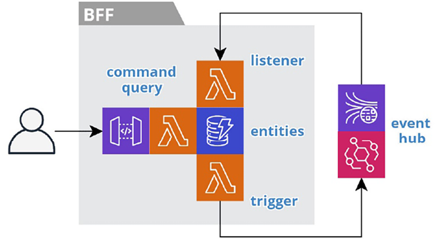
Figure 2.10: A typical service stack
The gray box logically equates to the service and physically equates to both the repository and the stack. The icons represent the cloud resources within the stack. We place icons next to each other to indicate communication. This results in tighter diagrams. The nearest arrow implies the flow of communication. A legend for all the icons is available in the preface.
We will cover more details of creating a stack in Chapter 6, A Best Friend for the Frontend, and Chapter 11, Choreographing Deployment and Delivery.
Persistence
Each service will own and manage its own data. Following polyglot persistence practices, each service will use the type of database that best supports its needs. These serverless resources are managed as part of the stack.
Services will consume domain events from upstream services and cache the necessary data as lean materialized views. The high availability of these serverless data stores creates an inbound bulkhead that ensures necessary data is available even when upstream services are not. This also greatly improves data access latency.
We will leverage the Change Data Capture (CDC) mechanism of a data store to trigger the publishing of domain events when the state of the data changes. We can also use CDC to control the flow of data within a service.
We will cover the details of the persistence layer in Chapter 5, Turning the Cloud into the Database.
Trilateral API
Each service will have up to three APIs: one for the events it consumes, another for the events it produces, and one for its synchronous interface. Not all these interfaces are required. Most services will consume events, but not all will publish events. For example, a BFF service that provides a read-only view of data would only consume events, cache the data, and provide a synchronous API to access the data. Control services and most ESGs do not have a synchronous interface.
Events
Following our event-first approach, the APIs for events are the most important, because they dictate how a service will interact with other services. A service should document the events it consumes and those that it produces. This could be as simple as a listing in the README file at the root of the repository. We can document the JSON structure of internal domain events using TypeScript interface notation. For external domain events, a standard such as OpenAPI (https://www.openapis.org) or JSON Schema (https://json-schema.org) may be helpful. The cloud infrastructure may provide a registry service to capture the schemas of all the event types in the subsystem. You can also use a tool like Event Catalog (https://www.eventcatalog.dev) to make it easier to explore the producers and consumers in your subsystem. We will cover events in detail in Chapter 4, Trusting Facts and Eventual Consistency.
API Gateway
Services operating at the boundaries of the system, such as BFFs, will have a synchronous interface. We will implement these using an API Gateway.
We design the API of a BFF specifically for a single frontend micro-app. One team owns the frontend and the BFF, so official documentation for the API may not be necessary. However, we may use a self-documenting API, such as GraphQL. We will cover BFFs in detail in Chapter 6, A Best Friend for the Frontend.
Some ESG services will also require an API Gateway, such as implementing a webhook to receive events from a third-party system or providing an Open API for your own SaaS system. We will cover the ESG pattern in detail in Chapter 7, Bridging Intersystem Gaps.
Functions
We will implement the business logic of an autonomous service as serverless functions using the cloud provider’s Function-as-a-Service (FaaS) offering, such as AWS Lambda. It is important to point out that while each function is independent, we will manage functions as a group within the stack that owns all the resources of the service. To account for this distinction, we will use the hexagonal architecture that we introduced in the Building on proven concepts section.
We will architect our functions at two levels, the nano or function level and the micro or service level. In other words, we need to architect the code within each function and architect the functions within each service. Now let’s dig further into the nano and micro architecture of our serverless functions.
Nano architecture
At the function or nano level, we scale our hexagonal architecture down so that each serverless function cleanly executes a fragment of the business logic within an autonomous service. Figure 2.11 depicts the structure and purpose of the code within an individual serverless function.
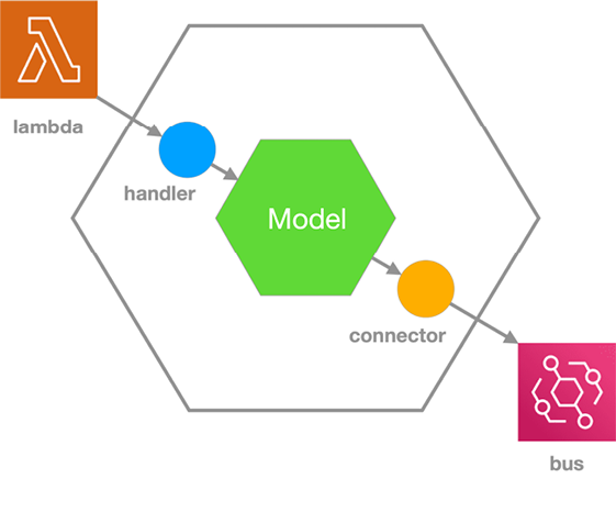
Figure 2.11: Function-level – nano hexagonal architecture
The FaaS service (that is, lambda) invokes a serverless function and dictates the signature of the input parameters. We do not want this signature to pollute our business logic. In turn, our business logic makes the outbound calls to cloud services, such as a bus or datastore. Again, we do not want the signatures of these cloud services to pollute our business logic. So, we will separate the business logic into a model and isolate these dependencies in adapters.
We will implement the business logic (that is, the Model) as classes and functions that expose cloud-agnostic interfaces (that is, ports). We will implement a handler function that adapts the lambda signature to the model. The handler will inject the model with a connector class that adapts the model’s outbound calls to the signature of the cloud service, such as the bus.
This nano architecture will allow us to easily move the model to a different runtime environment or even another cloud provider by substituting different implementations for the handlers and connectors. In Chapter 11, Choreographing Deployment and Delivery, we will see how this architecture facilitates a serverless testing honeycomb.
Micro architecture
At the service or macro level, we scale our hexagonal architecture to show how multiple serverless functions work together to implement the business logic of the autonomous service. Figure 2.12 depicts the structure and purpose of the resources within an autonomous service.
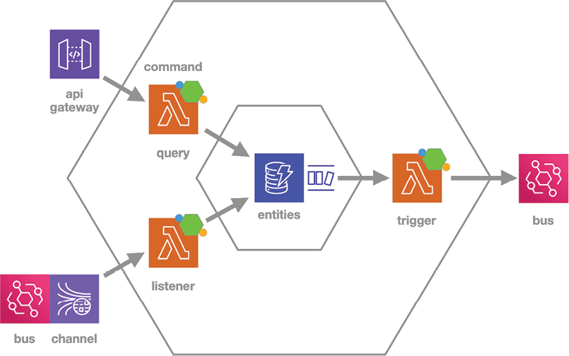
Figure 2.12: Service-level – micro hexagonal architecture
This diagram presents an expanded format of the same BFF services depicted in condensed format in Figure 2.10 to highlight the different roles played by the various resources.
We store the internal domain model in a dedicated datastore (entities) so that we can share the data across all the functions. This data represents the internal domain model of the service, and that data format defines the interface (that is, ports). The serverless functions act as adapters to map between the internal model and the external model.
An autonomous service will typically have two to five serverless functions. Each function has its own nano architecture with the appropriate handler and connector based on the cloud services it interacts with, such as AWS Kinesis, AWS API Gateway, AWS DynamoDB, AWS DynamoDB Streams, or AWS EventBridge.
The listener function sits on the driving side because it consumes domain events from a channel and collects the data that is a prerequisite for the capabilities of the service. It adapts the data from the incoming domain events to the internal domain model and saves the results in the local entities datastore.
The command/query function sits on the driving side because it supports the user actions that drive work through the subsystem. The nano model implements the business logic for the queries and commands and the function adapts the model for frontend communication.
The trigger sits on the driven side because it reacts to the state changes within the service. It consumes internal change events from the datastore’s CDC stream. It adapts the data from the change events to the domain event model and publishes the results.
The nano and micro levels work together to keep our architecture clean and decoupled. They enable the Command, Publish, Consume, Query (CPCQ) pattern that we use to connect services together to carry out the work of an autonomous subsystem. Work starts upstream. A user performs an action, and a command function updates the state of the domain model. Then a trigger function publishes a domain event to record the fact that the action occurred and drive further processing. Downstream, one or more listener functions take responsibility for consuming the domain event and cache the needed data so that their users can query for the information they need to perform the next action. We repeat this simple pattern as many times as necessary to deliver the desired functionality of an autonomous subsystem.
We will see examples of stream processor functions in Chapter 4, Trusting Facts and Eventual Consistency. We will also see examples of REST and GraphQL functions in Chapter 6, A Best Friend for the Frontend.
Shared libraries
We will tend to shy away from using shared libraries for reusing business logic between services. This will help us avoid the false reuse that creates coupling and complexity. We will use open-source libraries for crosscutting concerns. Over time, duplicated logic can be refactored into libraries when it proves to not be false reuse. We will cover false reuse in Chapter 13, Don’t Delay, Start Experimenting.
Now that we have defined our architectural boundaries, let’s see how we can let go and govern without impeding innovation.