

Although this topic is too big for the scope of this appendix, we'll work through the basics so that you understand how to get started.
Note
For more information on DirectXMath, visit: http://msdn.microsoft.com/en-us/library/windows/desktop/ee415574.
All the points (and vertices) are represented by using an array of three floats called a Vector, which represents the x, y, and z axes. In DirectXMath this is represented by the DirectX::XMFLOAT3 structure.
Note
For simplicity I'll avoid using the DirectX namespace in front of all the references, but, don't forget that all of DirectXMath sits within that namespace—so be sure to ensure you reference it in some way.
Most operations on this data are done by first converting the XMFLOAT3 to an XMVECTOR, which represents the SIMD (Single
Instruction, Multiple Data) units on the CPU. Two simple functions provide you with a way to get information in and out of XMVECTOR, shown as follows:
XMFLOAT3 start = XMFLOAT3(1, 1, 1);
XMVECTOR vec = XMLoadFloat3(&start);

XMFLOAT3 end;
XMStoreFloat3(&end, vec);
As shown, we Load the XMFLOAT3 into the XMVECTOR, and Store the result of our operations back into the XMFLOAT3.
But what about the matrices that we need for the camera? Those are provided using the XMMATRIX data type. In most cases you will use a couple of key methods to create and manipulate these matrices, as shown in the following code snippet:
XMMATRIX XMMatrixMultiply(XMMATRIX M1, XMMATRIX M2);
// World & View Matrices
XMMATRIX XMMatrixTranslation(float x, float y, float z);
XMMATRIX XMMatrixScaling(float x, float y, float z);
XMMATRIX XMMatrixRotationRollPitchYaw(float pitch, float yaw,
  float roll);
XMMATRIX XMMatrixPerspectiveFovRH(float fov, float aspectRatio,
  float nearZ, float farZ);
Most of these are straightforward, but, the last one may have some new concepts.
A perspective projection requires some information to correctly warp the scene so that we have vanishing points and a horizon. To do this, we need to provide the field of view (fov) and aspectRatio of the camera. In this particular case the field of view refers to the vertical field of view rather than the horizontal field of view that you may be used to.
The nearZ and
farZ parameters refer to how far the two clipping planes are from the position of the camera. A clipping
plane is the point where objects are no longer rendered. This prevents weird-rendering artefacts when models cross over the position of the camera, and allows you to define the farthest point from the camera—which is required for the depth parameter that is stored as a value from 0.0f to 1.0f.
These parameters combine to give you a matrix that defines a shape called a frustum, which contains everything visible in the scene.
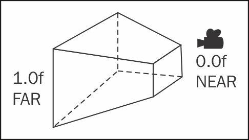
Camera frustum