
In this recipe, we'll see the several kinds of textures available in Cycles and learn how to use them with the shaders.
Similar to Blender Internal, we can use both procedural textures and image textures in Cycles. However, the Cycles procedural textures are not exactly the same as in Blender Internal; some are missing because of being replaced by an improved version (for example, Clouds has been replaced by particular settings of the Noise Texture) and a few are new and exclusive to Cycles.
We have already seen a simple construction of a basic Cycles material by mixing the diffuse and the glossy ("specular") components of a surface. Now let's have a look at the textures we can use in Cycles to further refine a material.
Because Cycles has a node-based system for the materials, the textures are not added in their slot under a tab as it is in Blender Internal, but they just get added in the Node Editor window and directly connected to the input socket of the shaders or other kind of nodes. This gives a lot more flexibility to the material creation process, because this way a texture can be used to drive several options inside the material network.
Starting from the previously saved
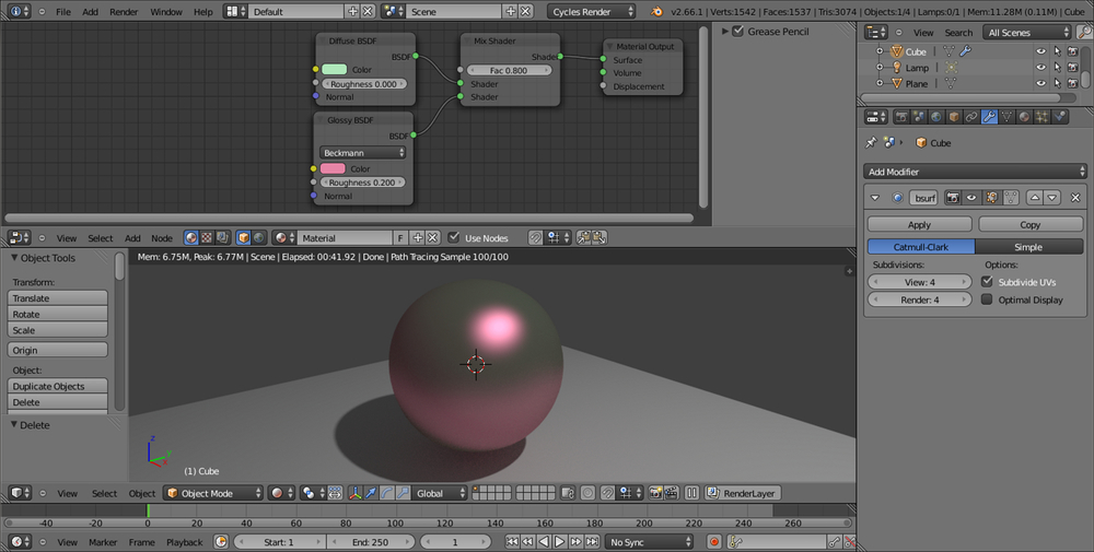
start_01.blendblend file, where we already had set a simple scene with a cube on a plane and a basic material, select the cube and go to the Object Modifiers window under the Properties panel to the right of the UI.Assign to the cube a Subdivision Surface modifier, set the Subdivisions level to 4, both for View as for Render.
In the Object Tools panel to the left of the 3D window, under Shading, set the subdivided cube (let's call it spheroid from now on) to Smooth.
Just to make things clearer, click on the color box of the Glossy BSDF shader to change it to a purple color (RGB set to 0.800, 0.233, and 0.388 respectively). Note, only the glossy reflection part on the spheroid is now purple, whereas the rest of the surface, the diffuse component, is still greenish.
Save the blend file and name it
start_02.blend.
Put the mouse pointer in the Node Editor window and press Shift + A.
In the contextual menu pop-up, go to the Texture item, just under Shader, and left-click on Wave Texture to add the texture node to the Node Editor window.
Grab and connect the Color yellow output socket of the texture to the yellow input socket of the Diffuse shader, the one close to the Color rectangle that we had formerly set as a greenish color:

In the Wave Texture node, change the Scale value to
8.500, Distortion to12.000, Detail to a maximum value of16.000, and the Detail Scale value to6.000.Now disconnect the texture color output from the Diffuse node and connect it to the color input socket of the Glossy shader:

Now disconnect the texture color output from the Glossy shader. Grab and connect the texture node's Fac output to the Roughness input socket of the Glossy BSDF shader, as shown in the following screenshot:

Save the file.
Delete the Wave Texture node (X key), press Shift + A with the mouse pointer in the Node Editor window and add a Checker Texture node.
Connect the Fac output of the Checker Texture node to the Fac input socket of the Mix Shader node, as shown here:

Save the file as
start_03.blend.
As is immediately visible in the Rendered viewport, at the moment the Wave Texture node color output is connected to color input of the Diffuse BSDF shader node, the spheroid looks as if it's painted in a black and white series of bands; actually, the black and white bands output of the texture node override the green color of the diffuse component of the shader, while keeping the material's pink glossy component unaltered (steps 1 to 3).
Exactly the opposite as you disconnect the texture output from the diffuse to connect it to the Glossy shader color input. Now we have the diffuse greenish color back and the pink has been overridden, while the reflection component is visible only inside the white bands of the wave texture (step 4 and 5).
In addition to the color output, every texture node has also a Fac output socket, outputting gray-scale linear values: connected to the Roughness input socket of the Glossy shader, the texture is working has a factor for its reflectivity. The working texture has a factor for its reflectivity; the spheroid keeps its colors and gets the specular-mirrored component only in the white-colored areas on the surface (that is, white bands equal to total reflecting and black bands equal to no reflection; step 6).
The Checker Texture fac (factor) output connected to the Fac input socket of the Mix Shader node works in a similar way: the numeric slider for the mixing factor on the Mix Shader node has disappeared, because now we are using the black and white linear values of the Checker Texture fac output as a factor for the mixing of the two components—the Diffuse and the Glossy—which, therefore, appear on the spheroid surface accordingly to the black and white quads (steps 8 and 9).
Every texture node has several setting options; all of them have the Scale value to set the size, the others change accordingly to the type of texture.
At this point you could wonder: "ok, we just mapped a texture on the spheroid, but what's the projection mode of this mapping?"
Good question. By default, if not specified and if the object doesn't have any UV coordinates yet, the mapping is Generated, which is the equivalent of the Original Coordinates mode (now renamed Generated as well) in Blender Internal.
But what if I want to specify a mapping method? Then, just follow these steps:
Press Shift + A on the keyboard with the mouse pointing in the Node Editor window again, go to the Input item and select the Texture Coordinate item, which is a node with several mapping modes and their respective output sockets.
Try to connect the several outputs to the Checker Texture | Vector input (the blue socket on the left-hand side of the node) to see the texture mapping on the spheroid change in real time, as shown in the following screenshot:

By the way, I'd like to point your attention to the UV coordinates output. Connect the link to the texture's vector socket and see the mapping on the spheroid disappear. Why is this? Put simply, because we haven't assigned any UV coordinates to our spheroid yet. Follow these steps to do so:
Go in the UV Maps tab in the Object Data window under the Properties panel on the right and click on the + sign. This just adds a one-to-one Reset UV projection UV layer to the object, that is, every face of the mesh is covering the whole area of the UV window (remember that although the cube looks like a spheroid now, this is only due to the effect of the assigned Subdivision Surface modifier; the UV coordinates work at the lowest level of subdivision, which is still a six-face cube).
A second option is to just place the proper seams on the cube's edges and directly unwrap the object in an UV/Image Editor window. Press Tab to go to edit mode, press A to select all the vertexes (if the vertexes are deselected). Now, press U and chose an unwrapping method from the pop-up menu (Smart UV Project and Cube Projection don't even need the seams), then go out of edit mode to update the Rendered preview.
The Texture Coordinate node is not needed in the case you unwrap an object and then use an Image Texture node, because in that case Cycles will automatically use the available UV coordinates to map the image map.
Obviously, the Texture Coordinate node alone is not enough. What we need now is a way to offset, rotate, and scale this texture on the surface:
Select the Texture Coordinate node and grab it to the left of the window, as far as suffices to make room for a new node. In the Add menu, go to Vector and choose Mapping.
Grab the Mapping node on the middle of the link that is connecting the Texture Coordinate node to the Checker Texture node; it will be automatically pasted in-between them, as shown in the following screenshot:

Now, start playing with the values inside the Mapping node. For example, set the Z Rotation value to
45°, the X Scale value to2.000and then slide the X Location value, while looking at the texture changing orientation, dimension and actually sliding on the x axis in the Rendered viewport.Save the blend file as
start_04.blend.
The Min and Max button on the bottom of the Mapping node are used to clip the extension of the texture mapping. That is, check both Min and Max to avoid the texture to be repeated n times on the surface and shown only once. A minimum value of 0.000 and a maximum value of 1.000 give a correspondence of one to one with the mapped image. You can tweak these values to even limit or extend the clipping. This is useful to map, for example, logos or labels on an object and avoiding repeating.