
For many of our projects, as we will be trying to make them as small as possible, we will probably not make use of the standard GPIO headers, which you most likely received with your Pi Zero W computer. Instead, we will be soldering our cables directly into our Pi Zero W. If you prefer to just test these projects out and would like to reuse your Pi Zero W for other projects, then it will probably make sense to sacrifice a bit of space and attach the GPIO headers to your Pi Zero W. Until recently, you only had one option to do this; solder the headers to your computer! This involves a steady hand, a keen eye, and some patience. I will talk you through this, as we are going to need to solder for many of the projects in this book; so it is a valuable skill to have even if you don't use it to attach headers to your Pi Zero. If the idea of soldering 40 very closely spaced pins onto your Pi Zero fills you with dread, you now have another option; many of the online stores stocking Raspberry Pi components now stock what are known as hammer headers. These allow you t attach the 40 small pins to the GPIO pins of your Pi Zero using only a hammer; no soldering required!
Connecting to GPIO headers
Hammer headers
You can purchase new hammer headers from a number of different retailers. Both Pimoroni (https://shop.pimoroni.com) and Pi Hut (https://thepihut.com) have them listed, and both companies ship to a wide range of countries.
Solder headers
The more traditional method of attaching your GPIO headers, and the one I have always used, is to solder them to the board. As I mentioned earlier, for most of the projects, I will not attach the header blocks in this manner and will just solder directly to the board; however, this is a skill worth learning, and some of the add-on cards or hats we will be using will require us to attach the headers before we can use them.
I include this section more for completeness about setting up a Raspberry Pi Zero, but as you will see in the projects in this book, I will be soldering our components directly to the Pi Zero and not making use of header pins. If you choose to solder the headers to your Pi Zero, then you will be able to follow the projects in the book by soldering to your header pins rather than directly doing so to the Pi.
Getting your equipment ready
You will need a soldering iron, some solder, and a blob of fixative such as Blu-Tack for this. I tend to always use leaded solder, as I find that it melts quicker and gives a better solder joint than unleaded solder, but the choice is yours.
Plug your iron in and allow it to come up to temperature. Once your iron is hot enough, apply a little solder to the tip. This is known as tinning your tip, and it fills any imperfections in your iron's tip with solder. This gives a better transfer of heat between the tip of your iron and the components your are soldering.
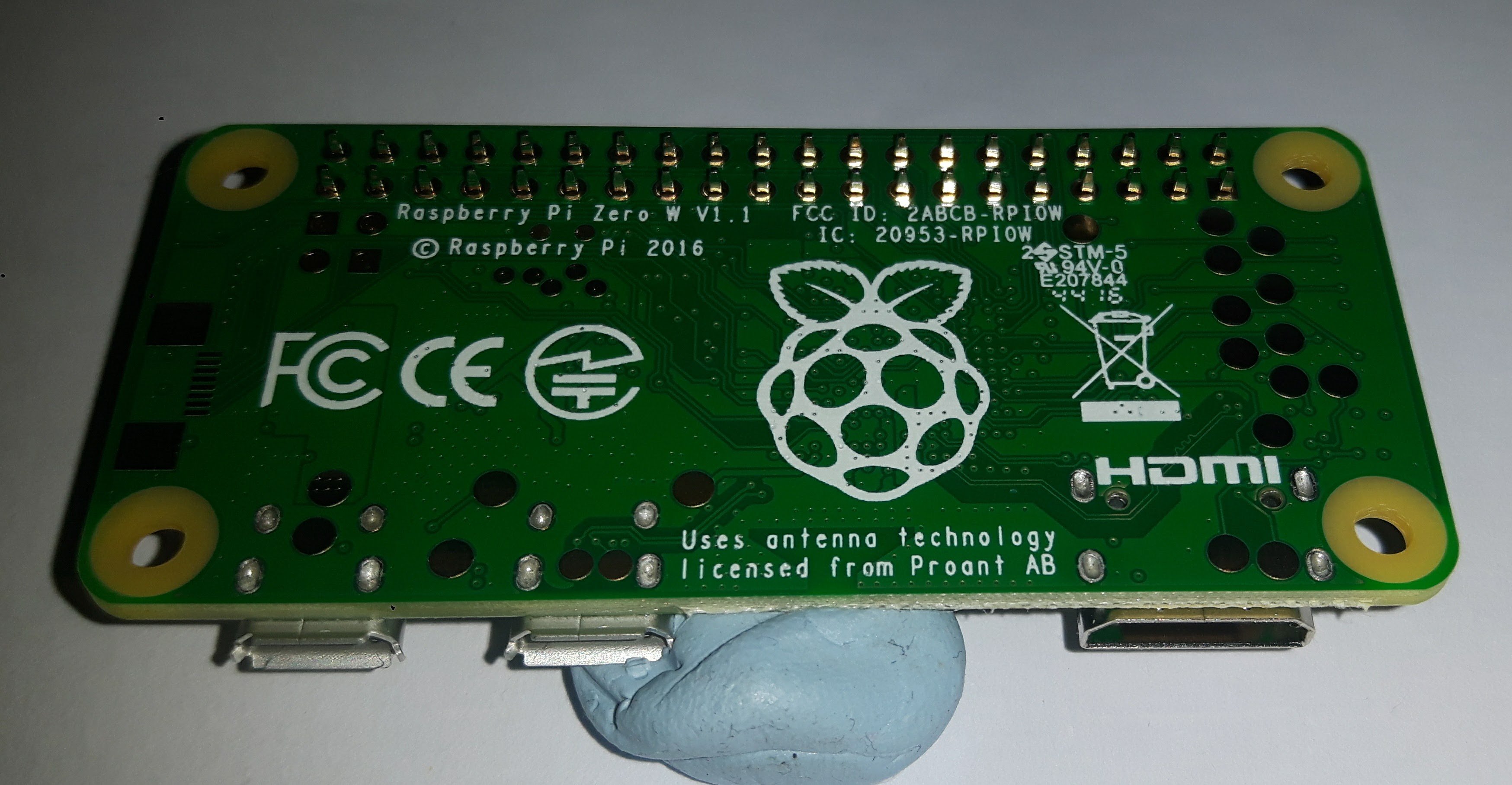
Now, insert the header into the Pi Zero and turn it upside down so that it is resting on the header pins evenly across the length of the Pi Zero. Then, place a blob of Blu-Tack under the side of the Pi Zero opposite the header pins, just enough to hold it flat while you begin to solder the pins, as shown here:
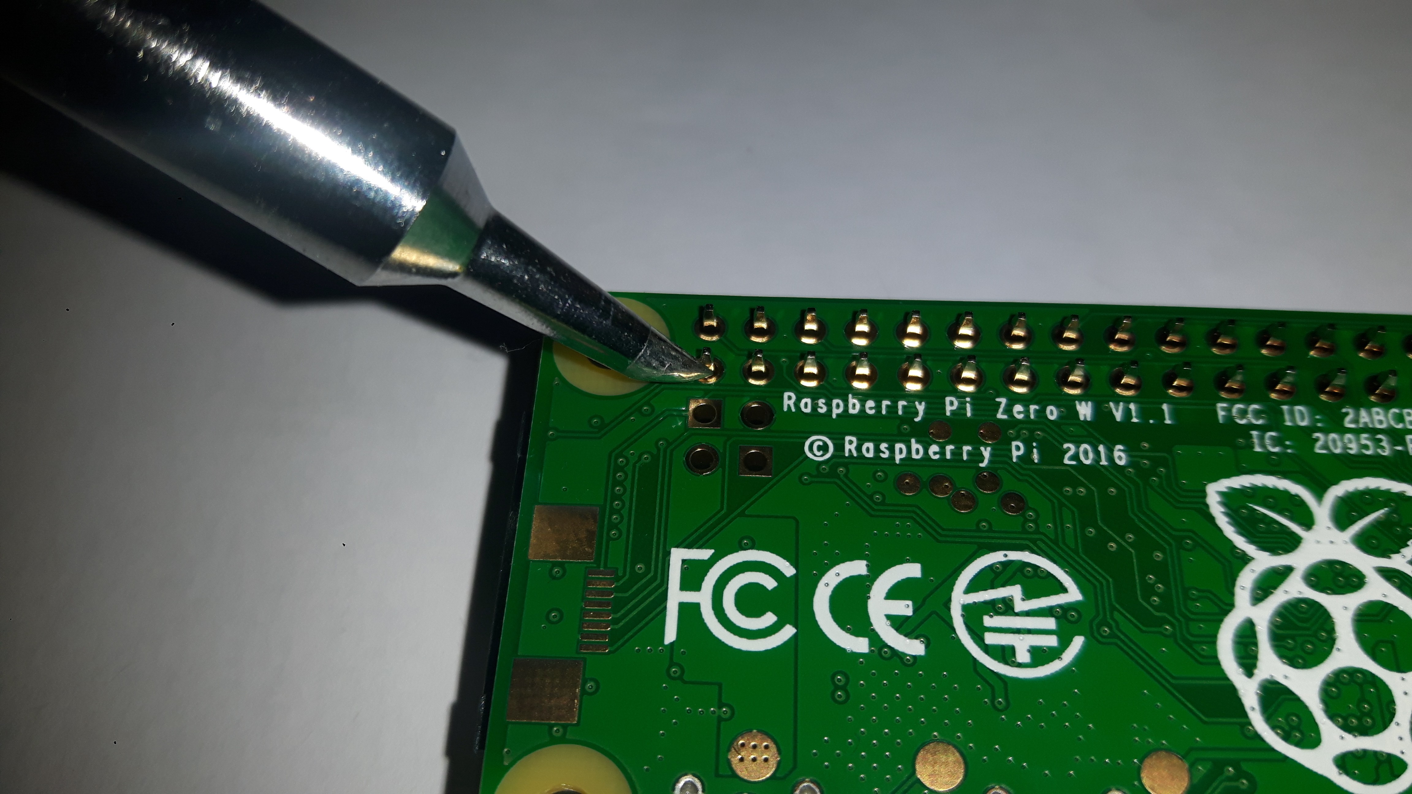
Now, we can begin to solder the pins to the Pi Zero; we are aiming for a nice, conical solder joint that just covers the brass ring around the hole in the Pi Zero board and comes to a point at the top of the pin. Place the tip of your soldering iron so that it touches both the brass ring on the board and the metal of the pin you are soldering, but nothing else, as shown next. Leave it for a few seconds to heat both brass ring and pin, and then apply the solder to the joint. The solder should melt, and you should see it flow into the hole and cover the brass and the pin. After a few seconds, remove the solder, and then remove your iron. Leave the joint to cool for a few seconds, and then move on to the next.
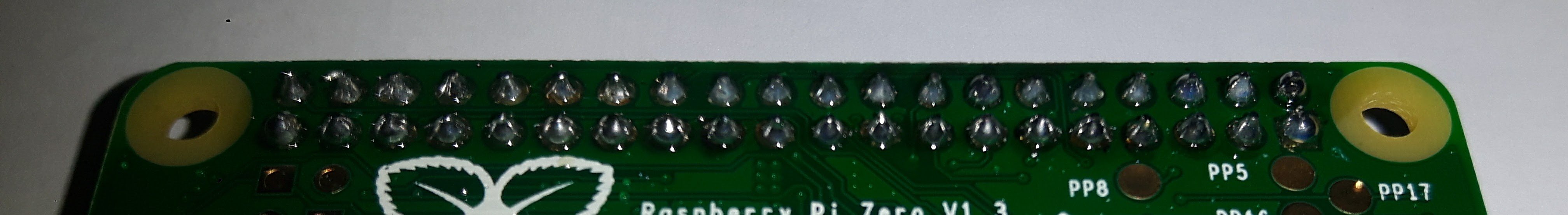
I tend to work my way down one side of the header and then rotate the Pi and solder the other side. The following picture shows what a finished soldered header should look like: