
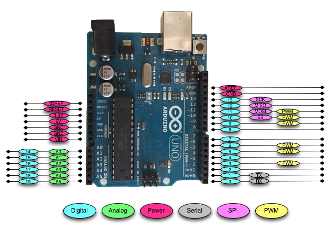
There is a total of 31 pins in the Arduino Uno pin headers. Most of these pins can be configured to perform different functions. The following diagram shows what the various pins can be used for:
Let's look at what the different pins do.


 Free Chapter
There is a total of 31 pins in the Arduino Uno pin headers. Most of these pins can be configured to perform different functions. The following diagram shows what the various pins can be used for:
Let's look at what the different pins do.
The digital pins on the Arduino are the ones that are used the most when connecting external sensors. These pins can be configured for either input or output. These pins default to an input state; therefore, when we are using a pin for input we do not need to explicitly declare them as input pins; however, it is good practice to do so because it will make it easier for someone reading our code to understand what the pin is being used for.
The digital pins will have one of two values: HIGH (1), which is 5V, or LOW (0), which is 0V. Once we start to program the Arduino, we will see how to read from or write to these pins.
The Arduino Uno contains a built-in Analog-To-Digital (ADC) converter with six channels, which gives us six analog input pins. The ADC converts an analog signal into a digital value. While the digital pins have two values, either high or low, the analog input pins have values from 0 to 1023 relative to the reference value of the Arduino. The Arduino Uno has a reference value of 5V.
The analog input pins are used to read analog sensors such as rangefinders and temperature sensors. The six analog pins can also be configured as digital pins if we run out of digital pins in our project.
Where the analog input pins are designed to read analog sensors (input), the PWM pins are designed for output. PWM is a technique for obtaining analog results with digital output.
Since a digital output can be either on or off, to obtain the analog output the digital output is switch between HIGH and LOW rapidly. The percentage of the time that the signal is high is called the duty cycle. The following diagram illustrates this concept:

We have the ability to set the frequency of how fast the signal can switch between HIGH and LOW. This frequency is measured in Hertz and sets how many times the signal can switch per second. For example, if we set the frequency to 500 Hz, that would mean that the signal could switch 500 times a second.
We will be using the PWM pins for several examples in this book and will examine them more when we learn how to program the Arduino.
The Arduino has several power pins. They are as follows:
These pins can be used for serial communication. The RX (digital pin 0) is used to receive while TX (digital pin 1) is used to transmit. These pins are connected directly to the USB-to-TTL serial chip. One note, you should not connect these pins directly to an RS-232 serial port because you will damage your board.
The Serial Peripheral Interface (SPI) pins are used for a synchronous serial data protocol that is used by microcontrollers for communicating with peripheral devices. This protocol always has one master with one or more slave devices. The pins are:
Now that we have quickly looked at the pins on the Arduino Uno R3 let's look at some of the different Arduino boards.
 Unlimited access to the largest independent learning library in tech of over 8,000 expert-authored tech books and videos.
Innovative learning tools, including AI book assistants, code context explainers, and text-to-speech.
50+ new titles added per month and exclusive early access to books as they are being written.
Unlimited access to the largest independent learning library in tech of over 8,000 expert-authored tech books and videos.
Innovative learning tools, including AI book assistants, code context explainers, and text-to-speech.
50+ new titles added per month and exclusive early access to books as they are being written.
 Notes and Bookmarks
 Search in title
 Add to playlist
 Download options
 Font size
Change the font size
 Margin width
Change margin width
 Day/Sepia/Night Modes
Change background colour