
Welcome to the M5Stack Core
In this section, you will learn the basic functions and features of the M5Stack Core. You will be able to perform the following tasks upon completing the lessons in this section:
- Power and reset the M5Stack Core
- Prepare the unit for programming
- Identify the three programmable user-interface buttons
- Identify the external ports for connecting electronic units
- Identify the USB port
- Identify the LED bars
- Select your stored applications
- Change the initial setup operation of the M5Stack Core
Upon completing this section, you will have a solid foundation of the external features and internal functions of the M55tack Core. Being able to complete these tasks will be important for programming and testing software applications that you create with your M5Stack Core. We will start the discussion with an overview of the M5Stack Core external features.
Powering and resetting the M5Stack Core
Turning on the M5Stack Core is quite easy to do. The M5Stack Core has a small red power button, as seen in Figure 1.1. The small red power button is located on the left side of the M5Stack Core. You turn on the M5Stack Core with a single press of the power button. You reset the M5Stack Core with a quick double press of the power button:

Figure 1.1 – The M5Stack Core power button location
Once the M5Stack Core is powered on, a UiFlow splash screen is displayed on the liquid crystal display (LCD), as seen in the following screenshot:
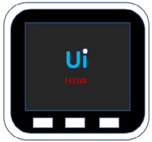
Figure 1.2 – UiFlow splash screen displayed after powering on the M5Stack Core
Initially, the M5Stack Core is programmed with 11 demonstration activities. The 11 demonstration activities are shown in the following diagram:
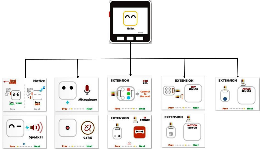
Figure 1.3 – UiFlow M5Stack Core demonstration activities
Next, let us learn about each demonstration activity through an accompanying explanation. We will explore the internal features of the M5Stack Core through a series of hands-on demonstrator activities:
- Demo 1 on/off: To turn off the M5Stack Core, a quick double press of the power button will accomplish this task, as seen here:
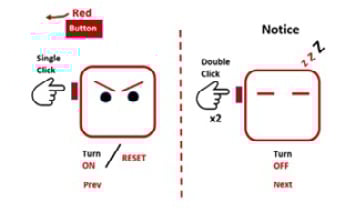
Figure 1.4 – The on/off operation of the M5Stack Core
- Demo 2 speaker: Press the center button on the M5Stack Core to hear a sound from the internal speaker:
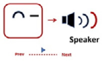
Figure 1.5 – Speaker demonstrator
- Demo 3 microphone: Speak into the pinhole microphone located on the side of the M5Stack Core. While speaking into the microphone, observe the line and sound wave images. Let’s see how this looks in the following figure:
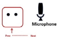
Figure 1.6 – Microphone demonstrator
- Demo 4 gyro: Tilt the M5Stack Core and observe the ball movement on the LCD screen. The movement is accomplished using a gyroscope and an accelerometer, as can be seen in Figure 1.7:
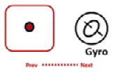
Figure 1.7 – Gyro demonstrator
- Demo 5 RGB LEDs: This demonstrator will glow and dim the sidebar RGB LEDs of the M5Stack Core. There is one LED bar on each side of the M5Stack Core:
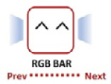
Figure 1.8 – RGB bar demonstrator
- Demo 6 ports explanation: The different electrical ports and their specific functions will be explored in this demonstration:
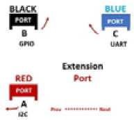
Figure 1.9 – Extension port demonstrator
Congratulations, you have completed exploring the internal features of the M5Stack Core. We will now learn about four sensor units from the M5GO IoT Starter Kit, which are shown in the following photo:
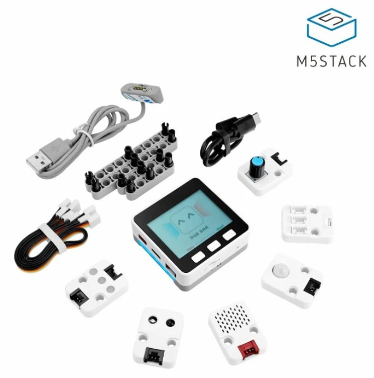
Figure 1.10 – The M5GO IoT Starter Kit
- Demo 7 environment sensor: The temperature and humidity levels are displayed on the LCD upon connecting the sensor to extension port A of the M5Stack Core:
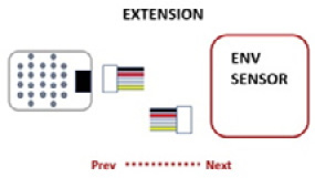
Figure 1.11 – Environment sensor demonstrator
- Demo 8 passive infrared (PIR) sensor: Attach the PIR sensor to extension port B of the M5Stack Core. You can observe a color change in the circle when placing your hand in front of the sensor. The color change response of the circle also occurs when you move your hand away from the PIR sensor. The following diagram illustrates the motion sensor’s response to a hand moved away from the PIR sensor:
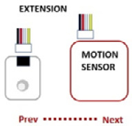
Figure 1.12 – PIR sensor demonstrator
- Demo 9 RGB unit: You explored the RGB LED bars in the fifth demonstrator activity. You will investigate the RGB LEDs packaged in this extension unit. This RGB LED unit will only light up when properly attached to extension port B. This diagram shows the wiring connector being attached to the RGB LED to connect to extension port B:

Figure 1.13 – RGB unit demonstrator
- Demo 10 infrared (IR) Remote unit: You can attach the IR Remote unit to extension port B using a wiring connector, as shown in Figure 1.14. Next, you take an ordinary IR handheld remote and point it toward the IR Remote unit. You can press any button on the IR handheld remote and observe the detection effect on the M5Stack Core LCD:
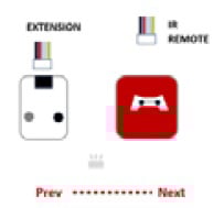
Figure 1.14 – IR Remote demonstrator
- Demo 11 angle sensor: You can test the knob on the angle sensor as shown in Figure 1.15, and observe the RGB LED bars getting brighter or dimmer:
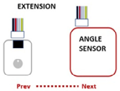
Figure 1.15 – Angle sensor demonstrator
Congratulations, you have learned about the M5Stack Core demonstrators. You have learned how to operate external sensors that are packaged with the M5GO IoT Starter Kit.
Note
To reinstall the firmware with the Demo app, use the M5Burner software. Select version 1.7.5 of the UIFLOW Core firmware. The name of the app is M5GO.py.
You have also learned how internal devices such as the RGB bar, microphone, and gyro operate using the appropriate M5Stack Core demonstrators. These mini hands-on demonstration activities allowed a glimpse into the M5Stack Core’s hardware architecture.
In the next section, we will dive deeper into the M5Stack Core’s hardware architecture by reviewing the electronic circuit schematic diagrams and the technical specifications of the ESP32-based programmable controller.