
Communicating with the M5Stack Core
You are now familiar with the M5Stack Core’s hardware architecture, UI design basics, and UiFlow IDE. In this section, you will learn how to set up the UiFlow IDE to communicate with the M5Stack Core. Being able to communicate with the M5Stack Core is important because the Blockly code applications you design and implement will now be tangible devices that people can use for controlling physical objects, such as LEDs, motors, and buzzers. You will be able to sense objects and environments using PIR and temperature sensors. Therefore, running software for these hardware components is dependent on communicating with the M5Stack Core device.
Requirements
To engage with this section’s learning content, you will need the M5GO IoT Starter Kit to explore the internal/external hardware electronics and software coding of your first basic application. In addition, the UiFlow code block software will be required to build and run the M5Stack Core application.
You will require the following:
- The M5Stack Core controller
- The M5GO IoT Starter Kit
- UiFlow Blockly code software
Communication setup
The initial step to communicating with the M5Stack Core is to turn on the programmable device. Press the power ON button. Once the UiFlow splash screen is displayed, press the rightmost button on the M5Stack Core. The rightmost button is the M5Stack Core’s Setup function.
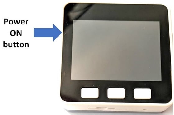
Figure 1.42 – Turning on the M5Stack Core
Then, perform the following steps:
- Scroll down to Switch mode.
- Scroll down to USB Mode. Use the middle button to select USB Mode.
These steps are shown in the following photo:
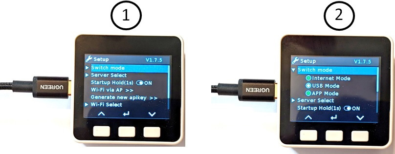
Figure 1.43 – Scroll to USB Mode
- Scroll down to reboot the M5Stack Core. Use the middle button to select the Reboot mode. After selecting Reboot, the USB API KEY splash screen will be displayed on the M5Stack Core unit’s LCD, as you can see in the following photo:
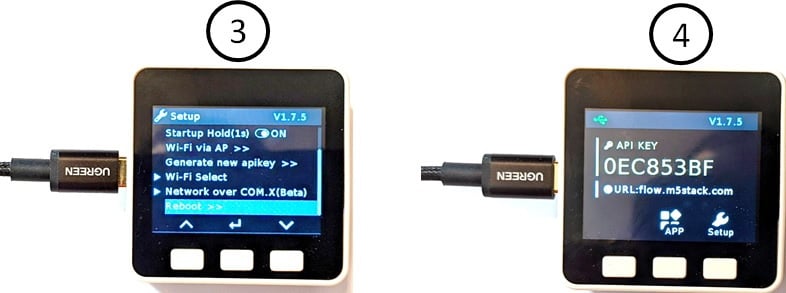
Figure 1.44 – Placing the M5Stack Core in USB mode (3 and 4)
You will then insert a USB-C cable into the M5Stack Core unit. Insert the other end of the USB-C cable into the development desktop personal workstation or laptop computer. Open the UiFlow Blockly code software. The Setting screen will appear on your personal desktop workstation or laptop screen. Select the M5Stack Core icon and the proper communication (COM) port, all of which you can see in the following screenshot:
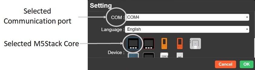
Figure 1.45 – Setting the communication port to select the M5Stack Core device
Once the M5Stack Core and communication port have been selected, click OK. The UiFlow IDE coding environment will be displayed on the screen as follows:
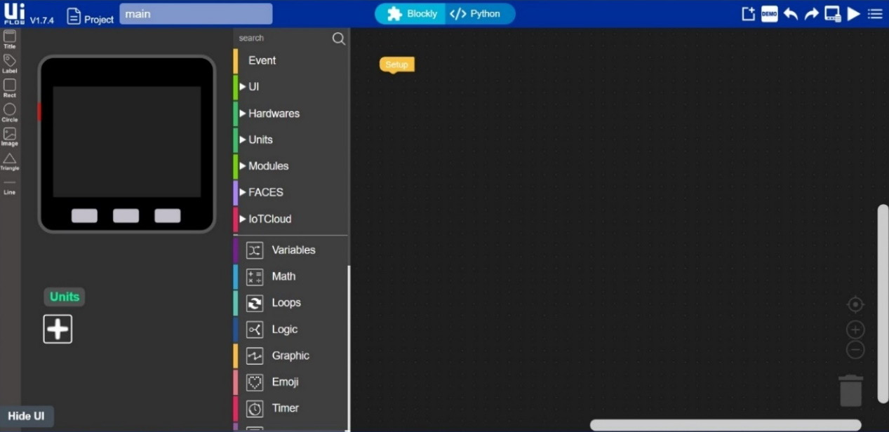
Figure 1.46 – UiFlow IDE
In the lower left-hand corner, you will see the Connected text displayed, as shown in the following screenshot:

Figure 1.47 – The M5Stack Core is connected to UiFlow Blockly code software
You will notice the COM4 port is displayed with the Connected text, which confirms that the selection for the communication port was correct. Congratulations, your M5Stack Core is now communicating with the UiFlow IDE! In Chapter 2, you will learn how to attach and program small electronic modules such as angle and motion sensors, an RGB (red, green, and blue) LED, and an IR Remote unit to the M5Stack Core. The knowledge you have obtained in this chapter will be used to explore M5Stack Units in Chapter 2.