Book Image

Mastering Arduino

By : Jon Hoffman
Book Image

Mastering Arduino

By: Jon Hoffman

Overview of this book

Mastering Arduino is an all-in-one guide to getting the most out of your Arduino. This practical, no-nonsense guide teaches you all of the electronics and programming skills that you need to create advanced Arduino projects. This book is packed full of real-world projects for you to practice on, bringing all of the knowledge in the book together and giving you the skills to build your own robot from the examples in this book. The final two chapters discuss wireless technologies and how they can be used in your projects. The book begins with the basics of electronics, making sure that you understand components, circuits, and prototyping before moving on. It then performs the same function for code, getting you into the Arduino IDE and showing you how to connect the Arduino to a computer and run simple projects on your Arduino. Once the basics are out of the way, the next 10 chapters of the book focus on small projects centered around particular components, such as LCD displays, stepper motors, or voice synthesizers. Each of these chapters will get you familiar with the technology involved, how to build with it, how to program it, and how it can be used in your own projects.
Table of Contents (23 chapters)

Fritzing diagrams

A Fritzing diagram is a picture representation of what the circuit should look like, similar to the open, closed and short circuit diagrams previously shown in this chapter; however, the Fritzing diagram has standard symbols to represent each part and a compact design making it easier to design more complex circuits. The following Fritzing diagram shows an Arduino connected to a LED and resistor on a breadboard:

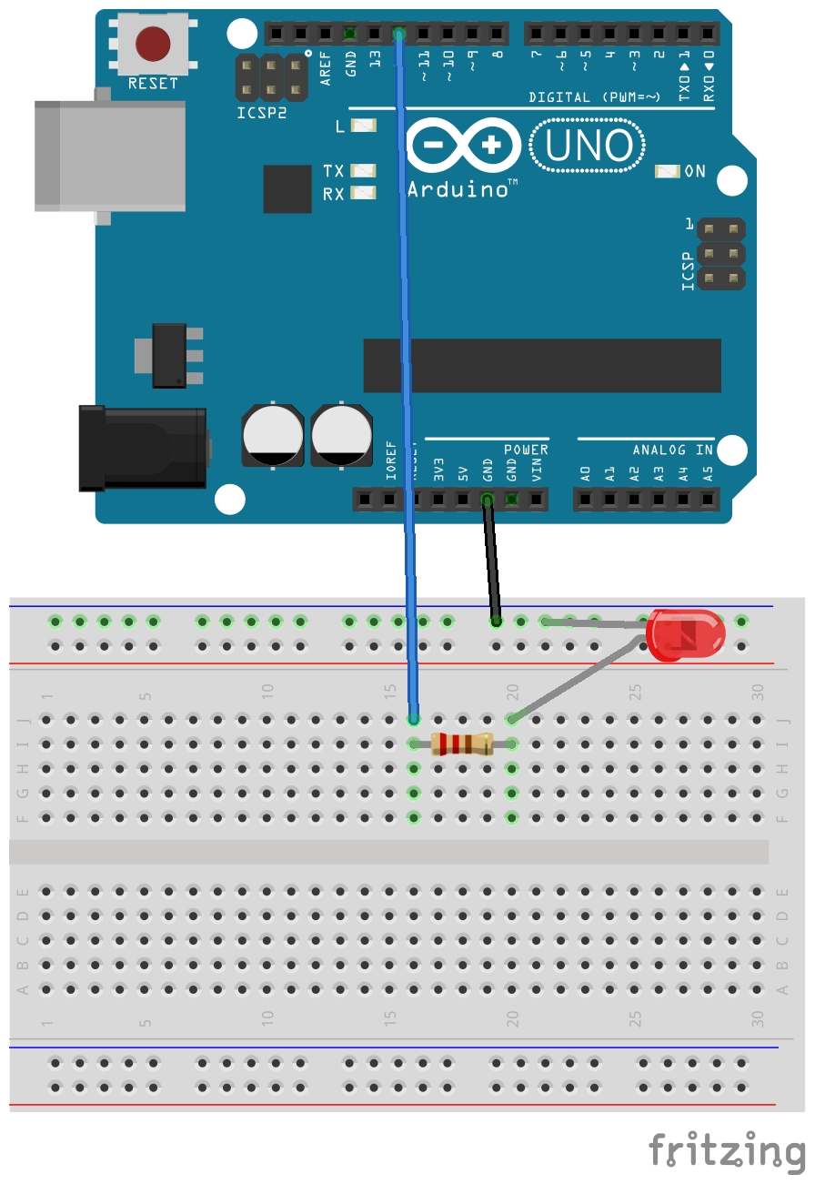
The circuit in this diagram starts with the Arduino GND pin, which is connected to the top rail of the breadboard. The cathode connector of the LED is also connected to the top rail, which connects it to the common ground from the Arduino. The anode connector of the LED is connected to a 220 Ohm resistor, which is connected to the digital 12 pin of the Arduino. This is a pretty easy diagram to understand because the diagrams look like the components...