
Architecture patterns overview
Now that you have a fair understanding of software architecture and design patterns, let’s talk about architecture patterns and their types.
An architectural pattern defines a repeatable architectural solution to a common problem in a specific use case. In other words, an architecture pattern describes how you arrange your functional blocks and their interaction to get a certain outcome.
An architectural pattern is similar to a software design pattern, but the scope of an architectural pattern is broader, while a design pattern is focused on a very specific part of the source code and solves a smaller portion of the problem.
There are different types of architectural patterns to address different types of problems, so let’s learn about some of those that are widely used. We will provide a high-level overview of these architectural patterns as diving too deep into them is outside the scope of this book.
A layered architecture pattern
A layered architecture is made up of different logical layers, where each layer is abstracted from another. In a layered architecture, you break down a solution into several layers and each layer is responsible for solving a specific piece of that problem. This architecture pattern is also known as an N-tier architecture pattern.
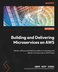
In this architectural pattern, your components are divided into layers and each layer is independent of the other but connects with its immediate layer through an interface to exchange information. Layered architecture focuses on the clean separation of concerns between layers and these layers are usually closed to other layers other than their immediate top layer. In a layered architecture, a closed layer always connects to its immediate layer, while an open layer architecture allows you to skip a layer in the layered chain. The following diagram shows an example of a closed-layered architecture:
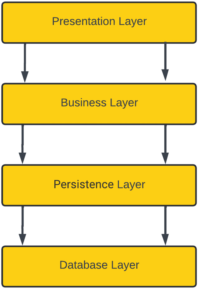
Figure 1.2 – Layered architecture pattern
In the preceding figure, we have divided an application component into four layers. The presentation layer contains any application code needed for the user interface. The business layer is responsible for implementing any business logic required by the application. The persistence layer is used for manipulating data and interacting with vendor-specific database systems. Finally, the database layer stores the application data in a database system.
All of these layers in a layered architecture only interact with the layer immediately below; this semantic is known as a closed layer. This approach gives you an advantage if you have to replace or change a layer; it doesn’t affect other layers in an application as there is no direct interaction between one layer and another non-immediate layer.
This style brings some complexity as well because some of the layers for certain scenarios can be just pass-through layers. In closed layers, you don’t do anything for a particular model or method but still have to go through all the layers, which can be a performance issue in certain scenarios. For example, while looking up a customer record on the user interface screen, no business logic is needed, but you still have to go through that layer to get a customer record.
To handle this kind of scenario, you can keep your layers open by allowing a direct call from the business layer to the persistence layer or a direct call from the presentation layer to the service layer, but that will bring more complexity to your architecture. Looking at the example shown in the following diagram, we have a five-layer architecture with an open style. Here, calls from one layer go directly to another layer by skipping some layers:
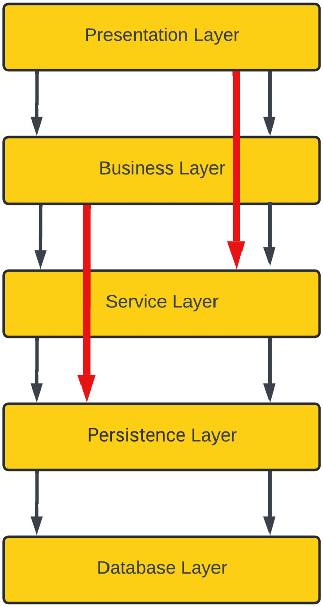
Figure 1.3 – Layered architecture pattern with open layers
In the preceding layered architecture pattern, if you need to change your persistence layer, then it is going to affect your service layer and, as a ripple effect, this will also affect your business layer. So, whether you want to keep your layers closed or open is an architectural trade-off you need to make.
A layered architecture pattern is very simple and easy to understand, and it can be easily tested as all the layers are part of the same monolithic application. Testing this architecture is easy as you don’t have to have all of your layers available at the same time – you can stub or mock the layer that isn’t available and simply test the other layers. For example, in the preceding diagram, if the presentation layer is not ready, you can test the other layers' flow independently or if any other layer isn’t ready, you can simply stub that out and mock the behavior that is expected from that layer and later on, that stub can be replaced by actual logic.
This architecture does scale well but it is not very agile as changing one layer will have a direct effect on the immediate neighboring layer and sometimes have a ripple effect on other layers as well; however, this is a great starting point for any application.
A microkernel/plugin architecture pattern
Microkernel architecture is also known as plugin architecture because of its plugin-based nature. Microkernel architecture is suitable for product-based development in which you have a core system or Minimum Viable Product (MVP) and you keep adding more functionality as needed so that it works to customize the core system and can be added or removed based on your needs. In this architecture, you need a registry in the core system that knows about the plugin you added and handles the request by utilizing the newly added module. Whenever you remove a plugin from the architecture, it will remove the reference from the registry.
Eclipse or Visual Studio Code IDEs are very good examples of microkernel architectures. As a core system, both of these are text editors and allow you to write code. Both of these IDEs can be extended by adding plugins to the core system; take a look at the following diagram, which explains the architecture of the Eclipse IDE:
Figure 1.4 – Eclipse IDE plugin-based architecture
In the preceding diagram, you can see that Eclipse is made up of hundreds of plugins; its core system is built with some basic functionalities that are extendable and allows any new plugin to be registered with the core system whenever you install a new plugin. Once a plugin has been installed, its functionality is available to use as a feature of the core platform, but if you remove that plugin, it only removes the functionality provided by the plugin.
Let’s take another example of a microkernel architecture pattern to understand it better. In a fictitious financial institution, a core system is designed to open an account by creating an account, opening the application, creating a user profile, generating an account statement, and using a system to communicate with the customers. A customer can see their application/account details on the account dashboard:
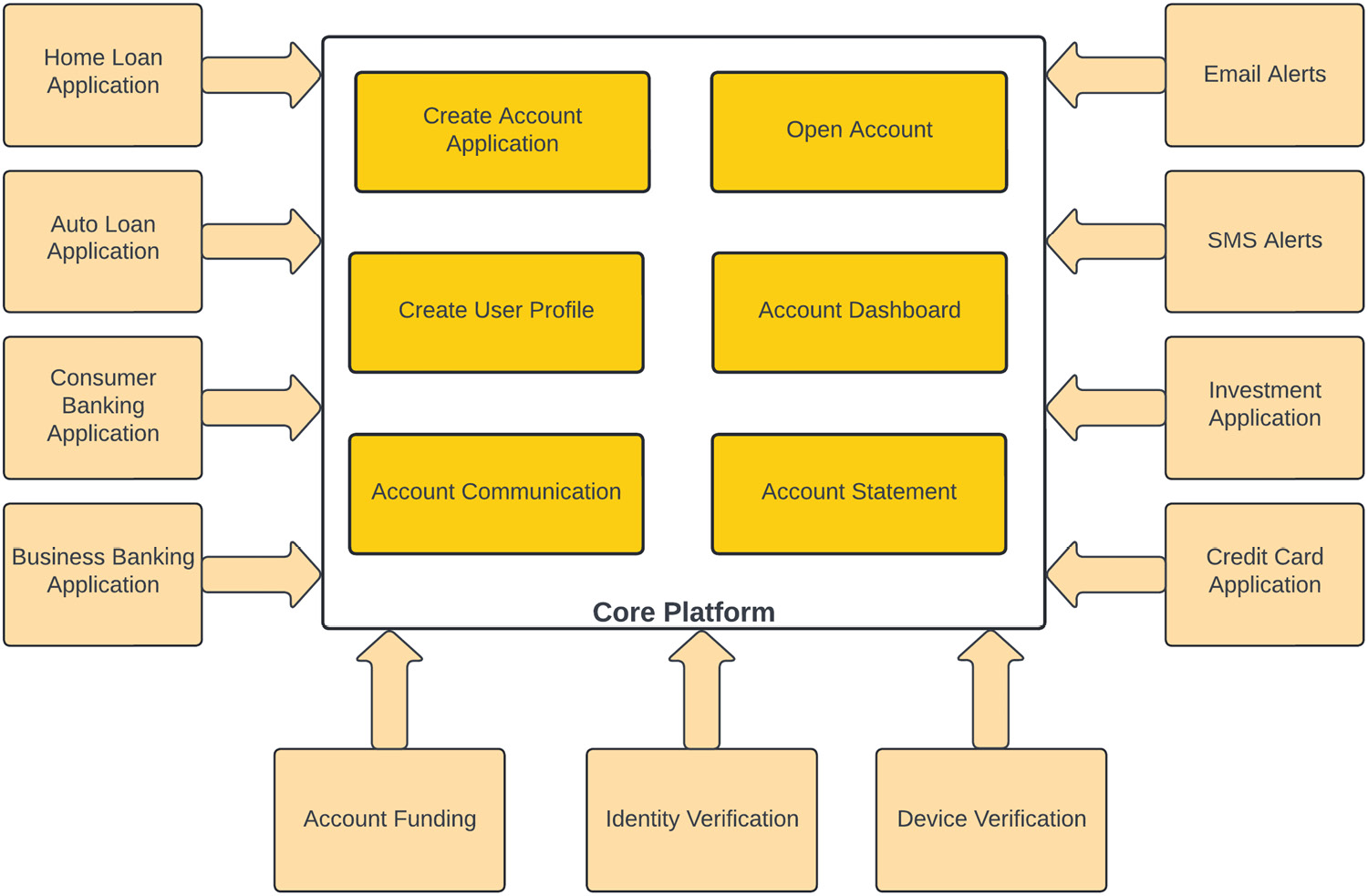
Figure 1.5 – Microkernel architecture for a financial institute
In this financial system example, the architecture core module can do normal account-opening activities, but this architecture is expandable, and we have added other functionalities in the form of plugins. This core module is being extended via plugin architecture to support credit card, home loan, auto loan, consumer banking, and business banking account types, and these plugins handle their specific type of functionality. By using a plugin architecture, each product type can apply its own rules.
The account communication module utilizes a microkernel architecture pattern and is being extended by adding support for email and SMS alerts. If an institution doesn’t want these features, they can simply not register/install these modules.
Similarly, validating a user device for login and verifying their identity and eligibility for a particular banking product has also been added in a microkernel fashion to the core system. Similarly, some banking products might have funding requirements, so you can add a funding plugin to supply that functionality to the core system.
To minimize the impact on the core system, plugins utilize a standard interface provided by the core system. This core system exposes an interface; all plugins must follow the same integration interface to be part of the core system.
If you want to utilize a third-party plugin, which doesn’t have a similar interface, you have to develop an adapter that connects to the core system and perform any translation needed.
This architecture pattern also falls into the monolithic architecture category as your entire package is part of the same application runtime.
This architecture pattern is pretty simple, agile, and easy to test as each module change can be isolated and modules can be added or removed as needed. Microkernel architecture is highly performant as all components become part of the same installation, so communication is fast. However, the scalability of the solution is still a challenge since all of these plugins are part of the same solution and you have to scale the entire system together; this architecture doesn’t give you the flexibility to scale any individual plugin. Another challenge with this architecture is stability, so if you have an issue with the core system, it will impact the functionality of the entire system.
A pipeline architecture pattern
Pipeline architecture patterns decompose a complex task into a series of separate elements, which can be reused. The pipeline pattern is also known as the pipes and filters pattern, which is a monolithic pattern. In this architecture pattern, a bigger task is broken down into smaller series of tasks, and those tasks are performed in sequential order; the output of one pipe becomes the input of another one.
For example, an application does a variety of tasks, which can be different in nature and complexity, so rather than performing all of those tasks in a single monolithic component, they can be broken down into a modular design and each task can be done by a separate component (filter). These components connect by sharing the same data format, with the output of one step becoming the input of another one. This pattern resembles a pipeline where data is flowing from one component to another like water flowing through a pipe, and due to this nature, it is called pipeline architecture. Pipes in this architectural style are unidirectional and pass data in only one direction:
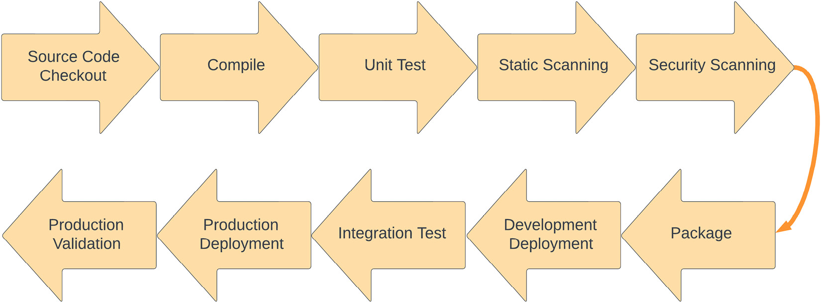
Figure 1.6 – A deployment pipeline example
The preceding diagram shows a typical deployment pipeline for a Java application, which is a great example of pipeline architecture.
A development pipeline starts with a developer committing code into a source code repository and performs the following tasks:
- The pipeline checks out the source code to the build server from the source code repository and then starts building it in the next stage.
- The source code is built and, if it is a compiler-based language, then code is compiled in this step.
- Once the source code has been built, unit test cases are executed and, on successful execution, the build progresses to the next step.
- The static scanning step performs the static (non-running) source code analysis to find any vulnerabilities or code issues. SonarCube and PMD are two famous static code analyzer tools.
- In the next step, the pipeline performs security scanning using tools such as Black Duck, Fortify, and Twistlock to find any runtime vulnerabilities.
- Once these quality gates have passed, the pipeline builds the final package for deployment and passes it to the deployment phase.
- In the deployment phase, the pipeline deploys the packaged application into the dev environment and passes control to the integration test phase.
- The integration phase runs the test suite, which is designed for validating the application, and makes sure that the end-to-end application is running with no issues.
- Once the integration phase has passed and the application has been validated, it is promoted to the higher environment for deployment. In this case, it is the production environment.
- Once the production deployment has been successful, the application is validated and verified for a successful production rollout and the pipeline is marked as completed.
We will talk more about the deployment pipeline in upcoming chapters as this book focuses on automating the deployment using AWS CodePipeline.
Now that we’ve had a refresher on pipeline architecture patterns, let’s talk a little bit about the different types of filters used in a pipeline architecture:
- Producer: Producers are the starting point of this architecture and have an outbound pipe only. In the preceding example, the Source Code Checkout stage is a producer.
- Transformer: Transformer filters take the input, process it, and send the output to another filter. In the preceding example, the Build stage is a transformer as it takes the source file and generates a compiled version of the source code.
- Tester: Tester filters are usually pass-through filters that take the input and call the other filters in the pipeline; sometimes, they can also discard the output. In our example, Static Scanning is a tester as it will perform scanning, and if anything fails, it will fail the phase without going through the different stages.
- Consumer: Consumer filters are the ending point of a pipeline architecture and can be recognized by the fact that they do not feed the output into another stage of the pipeline. In our example, the Production Validation stage is a consumer.
The pipeline or filter and pipe architecture is very simple and flexible and is easy to test, but scalability and performance are a problem since each stage of the pipeline must be completed sequentially. Small blockers in one of the pipeline steps can cause a ripple effect in subsequent steps and cause a complete bottleneck in the system.
A space-based architecture pattern
Scaling an application is a challenging task, so to scale this, you might need to increase the number of web servers, application servers, and database servers. However, this will make your architecture complex because you need high performance and scalability to serve thousands of concurrent users.
For horizontally scaling a database layer, you need to use some sort of sharding, which makes it more complex and difficult to manage. In a Space-Based Architecture (SBA), you scale your application by removing the database and instead have memory grids to manage the data. In an SBA, instead of scaling a particular tier in your application, you scale the entire layers together, known as a processing unit.
Important note
In vertical scaling, you add more resources such as memory and compute power to a single machine to meet the load demand, while in horizontal scaling, you join two or more machines together to handle the load.
SBAs are widely used in distributed computing to increase the scalability and performance of a solution. This architecture is based on the concept of tuple space.
Tuple space
Tuple space is an implementation of the associative memory paradigm for parallel/distributed computing. There’s a processing unit, which generates the data and posts it to distributed memory as tuples; then, the other processing units read it based on the pattern match.
The following diagram shows the different components of an SBA:
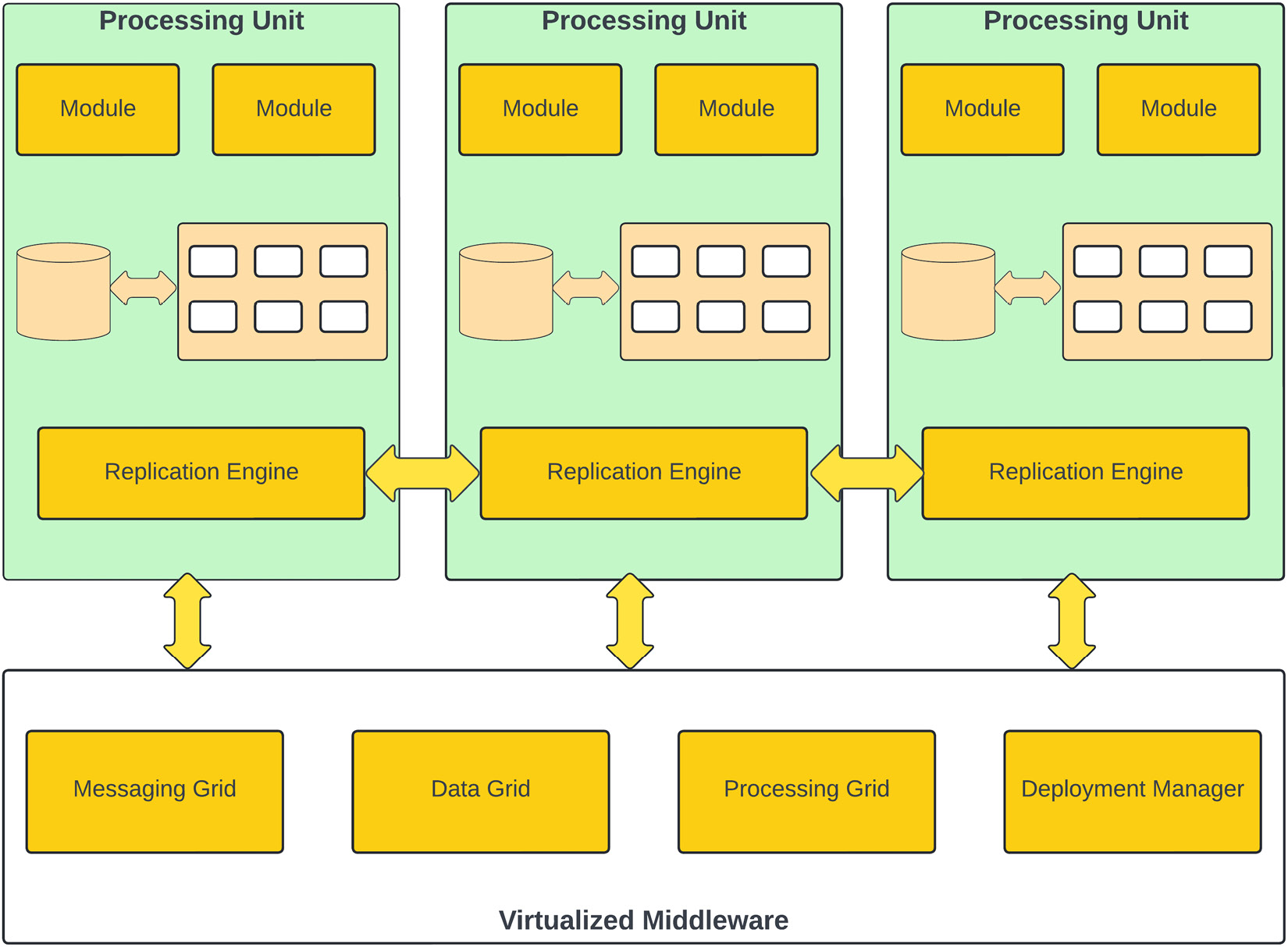
Figure 1.7 – SBA pattern
SBA comprises several components:
- Processing Unit: A processing unit is your application deployed on a machine and backed by an in-memory data grid to support any database transactions. This in-memory data grid is replicated to other processing units by the replication engine.
- Messaging Grid: This is a component of the virtualized middleware and is responsible for handling client requests and session management. Any request coming to the virtualized middleware is handled by the messaging grid, and it redirects that request to one of the available processing units.
- Data Grid: The data grid is responsible for data replication between different processing units. In a SBA pattern, the data grid is a distributed cache. The cache will typically use a database for the initial seeding of data into the grid, and to maintain persistence in case a processing unit fails.
- Processing Grid: This is an optional component of a space-based architecture. The processing grid is used for coordinating and combining requests to multiple processing units; if a request needs to be handled by multiple processing units, then the processing grid is responsible for managing all that. For example, if one processing unit handles inventory management while another handles order management, then the processing grid orchestrates those requests.
- Deployment Manager: The deployment manager is responsible for managing processing units; it can add or remove processing units based on load or other factors, such as cost.
In an SBA, all processing units are self-sufficient in processing client requests, but they are combined to make it more powerful for performance and scalability and use virtualized middleware to manage all that.
This architecture pattern is used for highly performant applications where you want to scale the architecture as traffic increases without compromising the performance. This architecture provides horizontal scaling by adding new processing units. Processing units are independent of each other and new units can be added or removed by the deployment manager at any time. Due to the complex nature of this architecture, it is not easy to test. The operational cost of creating this architecture is a little high as you need to have some products in place to create in-memory data grids and replicate those to other processing units.
An event-driven architecture pattern
Event-driven architecture (EDA) is one of the most popular architecture patterns; it is where your application is divided into multiple components and each component integrates using asynchronous event messages. EDA is a type of distributed system, where the application is divided into individual processes that communicate using events. This architecture pattern is made up of loosely coupled components that integrate using these messages. These messages are temporarily stored in messaging queues/topics. Each message is divided into two parts – a header and the actual message payload.
Let’s look at a simple example of an EDA for a hotel chain called “Cool Hotel,” which has chosen to deploy its reservation system using the EDA. A hotel Property Management System updates its inventory for available rooms, which is updated in Inventory System using an event message:
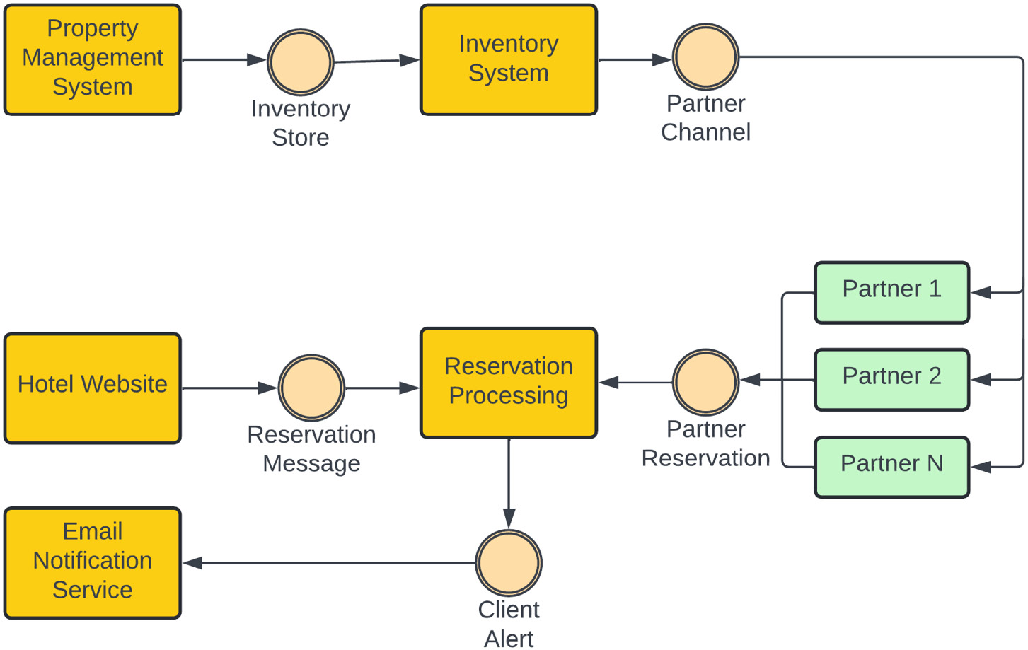
Figure 1.8 – Cool Hotel EDA example
Once Inventory System has been updated, it communicates that change to its partners through an event called Partner Channel, where different partners consume the message and update their listing.
Whenever a reservation is made either directly through the Cool Hotel website or through a partner listing, a reservation message is pushed to the Reservation Processing system, which then has the responsibility for multiple tasks. It updates the availability of the room by sending an event to Inventory Store and also generates an event, which is sent to the Client Alert system. As we have shown, all of our system components are very loosely coupled and are not aware of each other; they only communicate with each other through events.
There are several components in an EDA:
- Event generator: This is the first logical layer in the architecture. A component in an architecture that produces an event for other components to consume is known as an event generator or producer. An event producer can be an email client, a sensor, or an e-commerce system.
- Event channel: The event channel is the second logical layer in the EDA. An event channel propagates the information from the event generator to the event processing engine. This component temporarily stores the information in a queue and hands it over for processing asynchronously whenever the processing engine is available.
An event channel can hold the data for a certain time and remove it when either a retention period is reached or the processing engine can collect the event. This depends entirely on the underlying implementation of the event channel; Active MQ, AWS Kinesis, AWS SQS, and Kafka are a few examples of popular event channel implementations.
- Event processing engine: The event processing engine is the third logical layer in the EDA. This layer is responsible for selecting the appropriate event and then filtering and processing the event message received from the event channel. This layer is responsible for executing the action triggered by an event. In the preceding Cool Hotel example, the email notification service and inventory service are examples of event processing systems.
EDA is based on eventual consistency and it is near real-time due to the asynchronous nature of its events. This architecture is not a good choice if you need changes in real time. This architecture increases your availability but there is a trade-off you need to make in terms of consistency as your data can be inconsistent for a small amount of time until the asynchronous message has been processed.
This architecture brings agility to your product and it is highly scalable and improves performance, but it is hard to test these systems end to end. EDA is not simple to implement and you have to rely on a messaging system to find a reliable event channel.
EDA brings more complexities into the architecture as you have to deal with message acknowledgment, message re-delivery in case of failure, and dead letter queue analysis and processing for any corrupted events.
Dead letter queue
In a messaging system, a dead letter queue is a specialized queue that handles the messages that have been rejected or have overflowed from the main queue due to a message format issue, non-existing queue, message size limits, message rate limit, or software issues because of which a message is not processed successfully. Usually, dead letter queues work as a backup for main queues/topics and are used for offline processing and analyzing messages to identify any potential issues in the consumers or producers due to which messages are rejected.
A serverless architecture pattern
This is one of the more modern architectural patterns and has gained more and more traction recently. The name would make you believe that there is no server involved in this architecture, but that is not true. In this architecture pattern, rather than being responsible for all aspects of server infrastructure and management, you are utilizing the infrastructure owned by a third party and paying for the service you utilized. Serverless architecture is different from Infrastructure-as-a-Service (IaaS) offerings; in this architecture pattern, you are not responsible for managing servers, operating system updates, security patches, scaling up or down to meet demand, and so on.
Serverless architecture falls into two categories. Let’s look at what they are.
Backend as a Service (BaaS)
In this architecture style, instead of creating a backend service, you are utilizing a third-party provider. For example, your application requires you to validate the identity of a user. You could develop an authentication scheme and spend time and money on hosting the service, or you could leverage a third-party identity system such as Amazon Cognito to validate users in your system.
Taking this approach, you save on development efforts and costs. You reduce your overhead by not owning and managing the servers used for authentication; you only need to pay for the usage of the service.
This architectural model is not very customizable, and you have to rely a lot on the features provided by the third party. This approach may not be suitable for all use cases since the degree of customization required by some workloads may not be available from third-party providers. Another disadvantage of using this approach is that if your provider makes an incompatible change to their API/software, then you also need to make that change.
Functions as a Service (FaaS)
In this architectural style, you don’t have to use a third-party service directly, but you must write code to execute on third-party infrastructure. This architecture style provides you with great flexibility to write features with no direct hardware ownership overhead. You only pay for the time when your code is being executed and serving your client. The FaaS pattern allows you to quickly create business services without focusing on server maintenance, security, and scalability. This service scales based on the demand and creates the required hardware as needed. As a consumer, you just have to upload your code and provide a runtime configuration and your code will be ready to use.
With the increasing popularity of cloud computing, serverless architectures are a hot topic; AWS Lambda, Azure Functions, and Google Cloud Functions are examples of the FaaS architecture style.
This serverless pattern provides a lot of scalability and flexibility for customizing the solution as needed, but it has some downsides, and it is not suitable for all use cases. For example, as of December 2022, AWS Lambda runtime execution is limited to 15 minutes. If you have a task that takes longer than 15 minutes, then a Lambda function isn’t a good choice.
Let’s look at an example where AWS Lambda is a good solution. In the hotel industry, inventory rollover and rate rollover are scenarios where property owners want to set their inventory the same as last year and also want rates to be pretty much the same. Suppose you have a big event – for example, on July 4, which is Independence Day in the USA, your room rate will be high due to occupancy, so you want to maximize your profit and don’t want to sell your rooms for a lower rate than you might have a week before. So, property owners want to automatically set the same rate and room inventory as last year, but still want the flexibility to make a manual change or override, if necessary, through their property management system. For this kind of problem, you don’t need to have a service that is running 24/7 because you could instead have a scheduled job, which can be run on a daily or a weekly basis.
AWS Lambda can be a very good solution to this problem because it doesn’t require a server to do this job. An AWS Lambda function can be triggered by a CloudWatch schedule or EventBridge schedule event and call rate/inventory service to perform the rollover after providing the authentication token retrieved from the Amazon identity service (Cognito). Once this has been completed, the server that ran your function can be terminated by AWS. By using the serverless approach, you didn’t need to run your server all the time, and when your function was done executing, AWS was able to return the underlying hardware to the available pool. As of December 2021, sustainability is an AWS Well-Architected Framework pillar, so by using the Lambda approach here, you are not just able to control your costs but you are also helping save the environment by not running your server and burning more fuel:
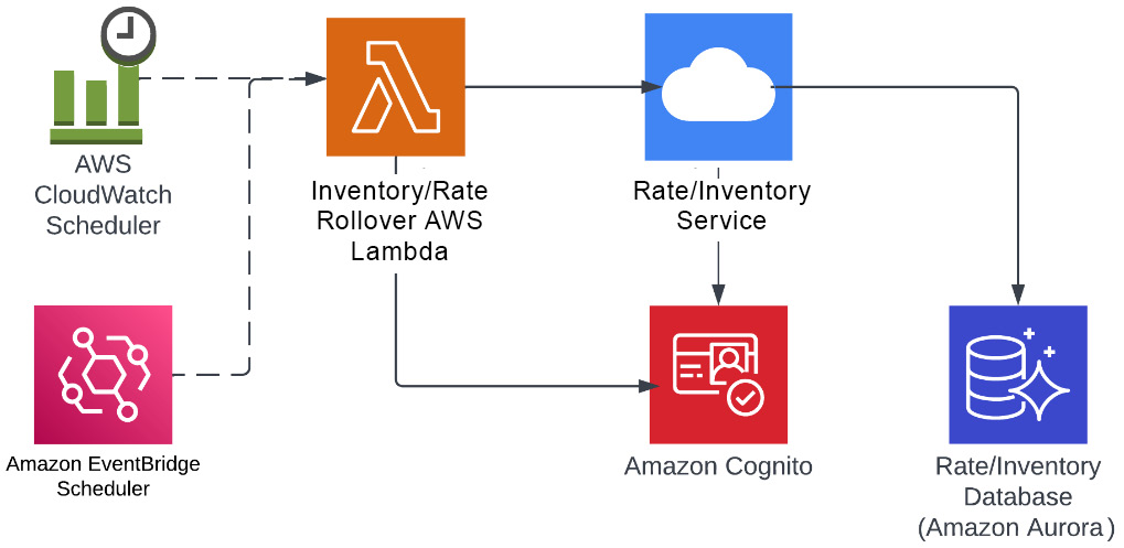
Figure 1.9 – Serverless architecture example for hotel inventory/rate rollover
In the preceding example, we use three AWS serverless resources. The first is an AWS Aurora database as a service, which helps write and read the data so that you don’t have to worry about how database servers are being managed or backed up.
The next service is AWS Lambda, which executes your code that performs the actual update to the database. You are not maintaining any server to run this code; you simply write a function in Python, Go, .NET, Java, or any of the other available runtimes, upload the code to AWS Lambda, and configure an AWS CloudWatch/EventBridge trigger (which can use either cron-style static repetition or can be set up to look for events in a log) to invoke the code. The final service is Amazon Cognito, which is used by AWS Lambda to retrieve an authorization token for the rate/inventory service; this is an example of the BaaS serverless architecture we discussed earlier.
Serverless architecture is a good design choice when you need scalability and your tasks can be executed within 15 minutes, and you don’t want to run your servers. It is also a very cost-effective architecture and brings agility to your solution because you only pay for the memory you provision for the Lambda, as well as the execution time. The initial request for these functions can be challenging as underlying infrastructure provisioning can take some time and you might need to prewarm your functions before they can take requests.
A service-oriented architecture pattern
Service-oriented architecture (SOA) is one of the widely used architecture patterns in enterprises and promotes the usage of services in an enterprise context. SOA is an enterprise integration pattern that connects different heterogeneous systems to carry out business functions.
In SOA, services communicate with each other in a protocol-agnostic way, but they may use different protocols such as REST, SOAP, AMQP, and so on. They share the information using a common platform known as the Enterprise Service Bus (ESB), which provides support for protocol-agnostic communication.
An ESB
An ESB is a centralized software component that is responsible for integration between different applications. Its primary responsibility is to perform data transformations, handle connectivity, messaging, and routing of requests, provide protocol-neutral communication, and potentially combine multiple requests if needed. An ESB helps in implementing complex business processes and implementing the data transformation, data validation, and security layers when integrating different services.
SOA is different from microservices architecture, which I will be talking about later in this chapter.
SOA is enterprise-focused since services target the entire enterprise. There are five types of services we focus on in an SOA; let’s take a look.
Business services
Business services are designed around the functionalities an organization has to perform to run its business operations. These services are coarse-grained and not very fine-grained:
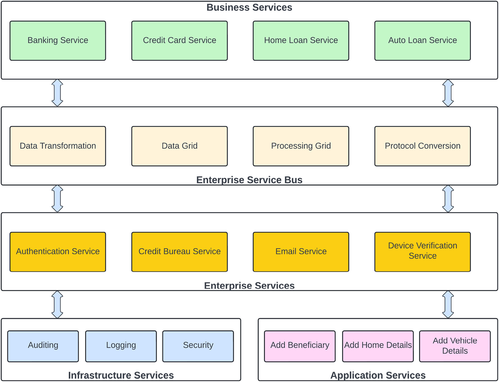
Figure 1.10 – Sample banking SOA example
You can identify a business service by filling in the blank in the following sentence: “we are in the business of ________.” For example, concerning a financial company, you can say the following:
- We are in the business of home loans
- We are in the business of credit cards
So, to support these two businesses, you need to create customers, so you might have a service in your architecture to create the customer but you can’t say that we are in the business of creating customers. So, any service that identifies your business is considered a business service in an SOA. If you take an example of a banking SOA architecture, as shown in the preceding figure, you can place Auto Loan Service, Credit Card Service, Banking Service, and Home Loan Service in the business services category.
Enterprise services
In an SOA, services that are used across an organization or enterprise are known as enterprise services. For example, authenticating a user is an organization-level issue, and you don’t want to have several applications implementing their logic to authenticate users if this can be done by a single service throughout the enterprise.
Another example of an enterprise service is managing customer information that can be shared by all other business services. For example, in a banking institution, you don’t want to maintain the customer information in home loan, auto loan, and core banking systems differently; the customer information might be different in each business unit. So, you should have an enterprise or shared service that is being utilized to maintain the customer information at a central place and being used by all of the business services across the enterprise. Enterprise services are usually owned by a shared service group or by an enterprise architect group.
In a banking SOA architecture, you would create capabilities that would be shared by multiple business applications. For example, many applications need to send emails to customers, so it’s sub-optimal for each one of them to “reinvent the wheel” of sending out emails; it’s better to have a dedicated email-sending task responsible for sending emails, handling undeliverable emails, and so on.
Application services
Application services are scoped to each application level and are fine-grained to a specific application. The scope of these services is specific to the individual application – for example, opening a business account, checking a customer’s credit card balance, or generating a credit card statement.
Application services have a very specific purpose for doing something related to the application context. Application services are owned by application teams within a line of business. In the banking SOA architecture example, you can see that adding a vehicle is a very specific service and limited to just doing one thing, so this is a very specific and application-level service.
Another example is adding home details for a home loan application. This is also very specific and categorized into an application-level service.
Infrastructure services
Infrastructure services are common concerns for the applications that don’t provide any features to the business application or application services but play a supporting role by providing platform-level features. Those services implement platform-level functions that are very generic and can be used by enterprise services, as well as by application services.
For example, logging is an integral part of any application, so that service will fall into the platform- or infrastructure-level services; any enterprise service or application service can use this for its logging requirements. Similarly, auditing data is not the core function of an application service, but governmental oversight or internal compliance organizations may require it, so an auditing service becomes a part of infrastructure services and can be invoked by application services as needed.
The ESB
In the middle of our sample banking architecture, we have an ESB, which is responsible for business process choreography, translating business data, changing message formats, or providing protocol-agnostic transmission. It is possible to have an SOA architecture without the need for an ESB, but then your services are dependent on each other directly and become tightly coupled with no abstraction.
SOA is not very simple to implement or easy to test, but this architecture is very scalable. The cost of implementing an SOA is a bit high as you have to be dependent on third-party software to have an ESB in the middle, although you might not need all the features provided by the ESB. Therefore, this architecture has a downside, and ESB can be a single point of failure.
A microservices architecture pattern
As the name suggests, the microservices architecture pattern promotes the usage of smaller services in a bounded context. Microservices architecture is a distributed architecture and is very similar to SOA, with some exceptions. In a microservices architecture, services are fine-grained and serve a specific purpose. In other words, microservices are lightweight and serve a very specific purpose while in SOA, services are more in the enterprise scope and cover a segment of functionality.
In the microservices architecture pattern, an application is divided into loosely coupled smaller self-contained components known as services. Each service runs in a process and connects to other services in a protocol-aware synchronous or asynchronous fashion if needed. Each microservice is responsible for carrying out a certain business function within a bounded context and the entire application is a collection of these loosely coupled services.
Unlike SOA, no message bus is involved in this architectural pattern. Microservices provide protocol-aware interoperability, so the caller of the service needs to know the contract and protocol of the service it is calling.
The following diagram explains the characteristics of a microservices architecture pattern. It explains how a microservices architecture is distributed and that each service is a separately deployed unit and designed around data domains within a bounded context exposed through APIs, where communication can happen with other services through API endpoints in synchronous mode or through events in asynchronous mode:
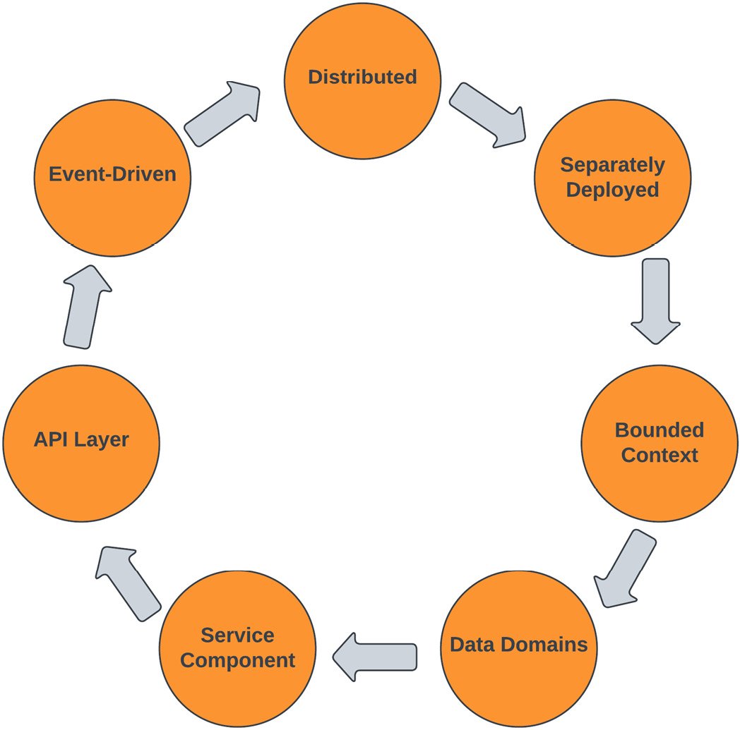
Figure 1.11 – Microservices architecture characteristics
I will provide more details about microservices in the upcoming chapters, but for now, let’s look at an example from the hotel industry:
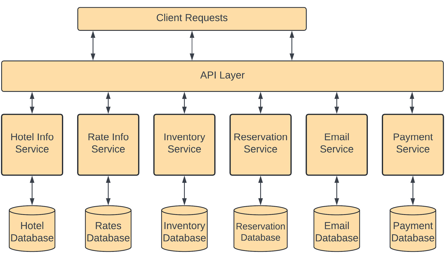
Figure 1.12 – Microservices architecture example
In this diagram, instead of having a single monolithic application taking care of the entire reservation process, the application is divided into several domain-specific services in a bounded context.
Hotel Info Service has a bounded context of hotel information, which keeps all the information related to a hotel, such as demographic information, the number of rooms, information about facilities, contact information, and so on. So, if you need to change anything within the context of a hotel, you need to make changes to this service.
Rate Info Service is responsible for managing the rates for each room type in a specific hotel for a specific night, based on demand or any specific events coming up. So, if any property management system needs to change the rate for any rooms in any hotel, they need to make a call to this rate information service.
Similarly, Inventory Service keeps track of the available hotel room inventory and is responsible for adding or removing a room from the inventory when a reservation is canceled or made. Reservation Service is responsible for creating a reservation within the system and updating the hotel’s inventory. Although the reservation system has its own database, those changes need to be reflected in the inventory database as well.
Each of these services has a bounded context and provides a specific business function. Services provide an API layer, which is how they interact with each other and external requestors. The division of functionality is done so that each service is autonomous. This architecture is very agile and scalable because it allows you to develop each service individually without affecting others. It can make testing simpler as well because a service will have a defined API, which your test harness can utilize to confirm that your service is not only service accepting valid requests and rejecting invalid ones but the response from the service is also matching the API.
One negative aspect of the microservice pattern could be the potential impact on performance; each service must invoke another service over the network or communicate through a messaging system asynchronously, which is subject to latency, and this can cause issues. Your microservice must also be architected to withstand packet loss, out-of-order responses, and other realities of a network backbone. This architecture pattern can also lead to additional complexity, as anyone who has tried to break apart the monolith can tell you. We will learn more about microservices and their benefits and drawbacks, as well as how you can write better microservices, in the next chapter, where we will learn about a monolithic application and how you can overcome the issues a monolithic application creates.
A service-based architecture pattern
Service-based architecture is a distributed architecture pattern and is based on service taxonomy. In the previous sections, you learned about the microservices and SOA patterns. Both of them sound very similar, with one exception – microservices architecture services are very fine-grained while SOA services are coarse-grained, with messaging middleware. This architecture pattern solves the complex problems faced in the SOA and microservices architecture patterns, so it is a kind of balance between both of those architecture patterns.
When you first try to “break apart the monolith” to convert it into a series of microservices, you will soon discover that isolating functionality and determining the area of responsibility for each function can be quite difficult. Remember, in a true microservices architecture, there is no direct access from one function/process to the data store of another. Deciding where data needs to reside, and the degree of data duplication you’re willing to accept, can be daunting. Since each microservice has a database, aggregating that data and accessing it from different services is a challenge.
Additionally, when designing a microservice, you should incorporate DevOps principles from the very beginning; using an automated pipeline may be more difficult when starting, but will pay off handsomely later when you have 20 or more microservices that need to be managed. We will learn more about this in the next chapter, where I will explain some design patterns related to microservices.
So, implementing the microservices architecture from ground zero is not an easy task and requires rewriting the entire application and defining the communication and orchestration patterns; on the other hand, SOA is focused more on the enterprise level and requires the messaging bus, which adds additional cost and complexity to the architecture. So, we need a middle ground as a basis to move away from a monolithic architecture to a microservices architecture, and SOA provides that to us.
In service-based architecture patterns, services are coarse-grained and based on the application domain, instead of a specific purpose-bounded context. In this architecture style, services share the same database and interact with each other in a protocol-aware fashion, so we don’t need an ESB to work as middleware. In this architecture, we divide the application into parts of related functionality to create services. The service granularity is considered macro and contains a bunch of modules that make sense based on the transaction scope of the application and avoid the service orchestration overhead we have in a microservices architecture.
Service-based architecture focuses on extracting the related functionality from an application into the services so that the transaction boundary of the functionality can be done within the same service and no distributed transaction, service orchestration, or choreography is needed between these services. You can create these services around the complex functionalities within your application. These services are called macro-services or application services as they take a portion of the full application, while microservices target a single purpose. This architecture style creates tight coupling between complements within a service, but a lot of organizations use this architecture style as a stepping stone toward a full microservices-based architecture.
In this architecture style, all the services access the shared database, so any issues or downtime to the database can impact the entire application. In a service-based architecture, communication between services is protocol-aware and services share contracts; any change to these contracts can impact the other services. Since no middleware is involved between services, it makes it simple and easy to implement. Some variations of this architecture can have a lightweight integration hub in between services, which can help in translation and service orchestration.
For example, an e-commerce site has several modules to carry out its business functions, so breaking it down into a microservices architecture will take significant effort and create additional overhead in setting up automated pipelines and dividing each module into a single feature-focused, bounded context service. So, the functionality is divided into portions – order-related functions are handled by Order Management Service, vendor-related functions are carried out by Vendor Management Service, and all customer-related functions are separated by Customer Management Service. However, all of these services access the same database, and communication between these services is done through REST-based APIs:
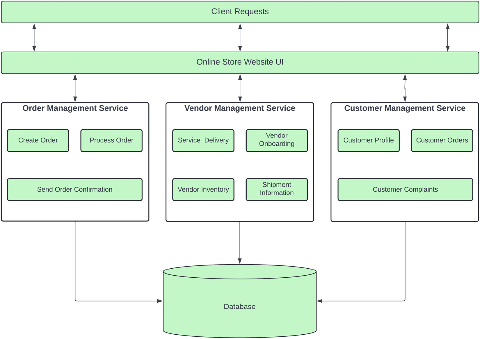
Figure 1.13 – Service-based architecture of an online store
The application user interface is deployed as a separate service. Communicating with the required services through their APIs is similar to a microservices architecture; the only difference is that these services handle a bigger responsibility and are not focused on a single purpose.
In a service-based architecture, there are fewer services compared to microservice-based architecture, so it makes it simple and you don’t have to have automated deployments from day one. This makes deploying these services a bit easier in the sense that not thousands of them are involved and you can eventually build your release pipelines. The performance of this architecture is higher compared to a microservices-based architecture since you are not communicating with several services to perform a single business function. This architecture is also cheaper compared to SOA as no heavy messaging bus is needed to implement this architecture. These services are a little hard to develop as they contain the entire functionality of a complex business feature, which needs to be understood well by the development team and poses a challenge in making frequent releases.