Book Image

Learn Robotics Programming - Second Edition

By : Danny Staple
Book Image

Learn Robotics Programming - Second Edition

By: Danny Staple

Overview of this book

We live in an age where the most complex or repetitive tasks are automated. Smart robots have the potential to revolutionize how we perform all kinds of tasks with high accuracy and efficiency. With this second edition of Learn Robotics Programming, you'll see how a combination of the Raspberry Pi and Python can be a great starting point for robot programming. The book starts by introducing you to the basic structure of a robot and shows you how to design, build, and program it. As you make your way through the book, you'll add different outputs and sensors, learn robot building skills, and write code to add autonomous behavior using sensors and a camera. You'll also be able to upgrade your robot with Wi-Fi connectivity to control it using a smartphone. Finally, you'll understand how you can apply the skills that you've learned to visualize, lay out, build, and code your future robot building projects. By the end of this book, you'll have built an interesting robot that can perform basic artificial intelligence operations and be well versed in programming robots and creating complex robotics projects using what you've learned.
Table of Contents (25 chapters)
1
Section 1: The Basics – Preparing for Robotics
7
Section 2: Building an Autonomous Robot – Connecting Sensors and Motors to a Raspberry Pi
15
Section 3: Hearing and Seeing – Giving a Robot Intelligent Sensors
21
Section 4: Taking Robotics Further

Driving a robot from IMU data

In previous chapters, we saw how to use the PID algorithm, and in this chapter, how to detect a pitch, roll, and yaw from a magnetometer. Our robot can't move its pitch or roll, but it can change its heading.

In this demonstration, we'll get the robot to stay on course—to try to track North regardless of where we turn it. Let's see how. Have a look at the following diagram:

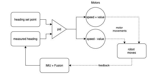
Figure 16.19 – Drive to heading behavior

Figure 16.19 shows the flow of data. The left of the diagram starts with a measured heading, and a heading setpoint going into a PID—the error value will be the difference between the two. The measured heading has come from the IMU + Fusion algorithm. We use the PID output to drive the motors so that they move at a fixed speed plus or minus the value, so the robot will turn to reduce the error. The robot moving will feed back into the IMU + Fusion algorithm, looping through...