

Let's take a look at Unreal Engine 4 and its editor. I am assuming that you have already installed the engine and visual studio 2013 on your machine; therefore, I will skip the process of registering, downloading, and installing the engine. If this is not the case, you can go to the epic website (www.unrealengine.com), sign up for free and get your copy by following their instructions with a couple of easy steps.
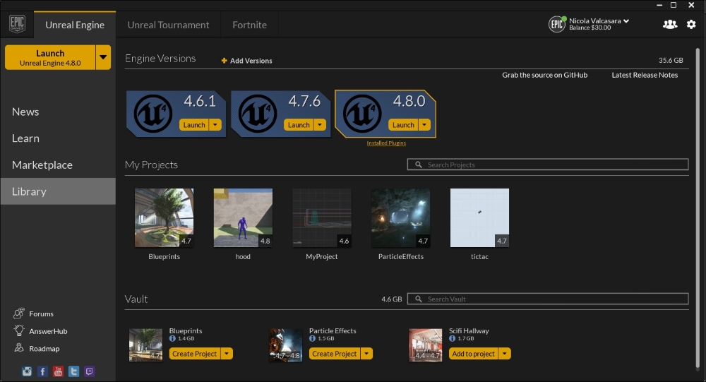
Open the Unreal Engine Launcher. Under the Library section, choose the version of the engine that you prefer, and launch it, as follows:
The Unreal Project browser will open. By default, you will see the Projects screen. Here, you can see your projects and the samples that you downloaded from the Marketplace. For our purpose, we want to create a brand new and empty project. Under the New Project section, you can choose between the Blueprint or C++ projects in a list of built-in templates:
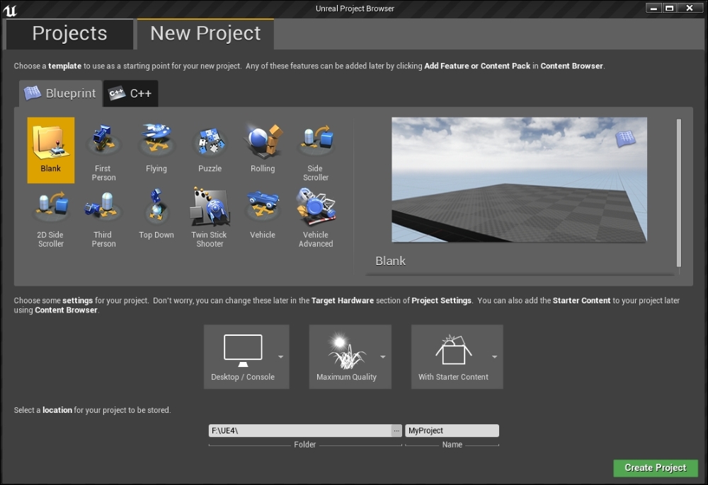
Due to the nature of Blueprint, the code and Blueprint live happily together. These choices are different in only one way: the C++ project will also create the visual studio solution for your project but each of those choices will generate the same Uproject and the needed files to launch the editor.
Due to this harmony between Blueprint and code, if you choose to create a project from the Blueprint section you can, at any time, generate its C++ project: the engine will create the Visual Studio solution as soon as you add your first code class from the editor (File | Add Code to Project).
Choose a Blank Blueprint project, name it and choose a location (the default is C://Users/Your Name/Documents/Unreal Projects/). Before creating the project you can also set three main aspects of it: the general graphic quality, the device target (mobile, pc, console), and if you want to you can include the Unreal Engine Starter Content in it (the Starter Content contains some useful general purpose assets such as primitive meshes, particle effects, materials, and so on).
For our purpose, we can leave those settings as is and click Create Project.
Welcome to the Unreal Engine 4 editor. You will now see the example map opened and ready for your input in front of you. We are not creating anything fancy right now: we will only explore the user interface of Blueprint and start to learn the basic commands and shortcuts in Blueprint.
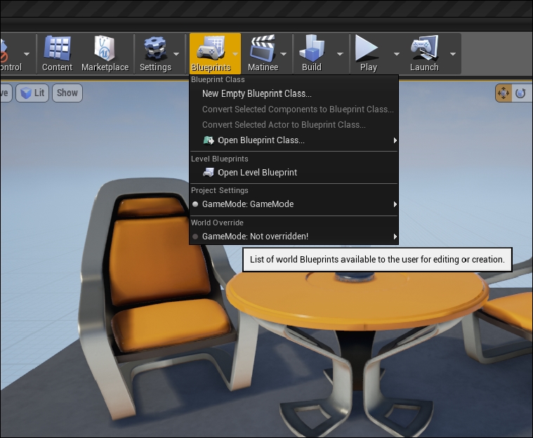
There are two ways to create a Blueprint class: from Content Browser or from the top tool bar. The toolbar Blueprint button gives you quick access to the existing modifiable Blueprint classes and you can access to the Level Blueprint only from here. Be aware that from here you can only create the Blueprint class. If you want to create, for example, Blueprint Macro Library, you need to use the Add New button from the Content Browser:
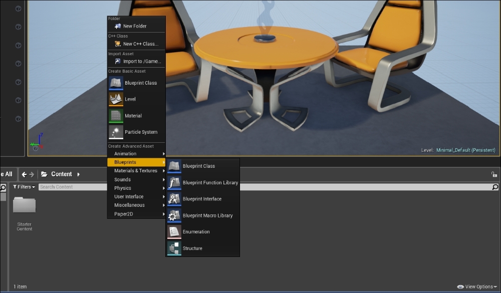
The Add New button and its equivalent mouse command (right-click in the Content Browser), will open a pop-up menu with all the assets that you can create in the engine, as follows:
Most of the asset needed for you projects can be created in the editor. We are now focusing on Blueprint; however, it is worth specifying what we can create from this menu and what needs to be created with an external software:
|
Can be created in Unreal Editor: |
Needs to be created using an external software: |
|---|---|
|
Game Levels Materials Particle Systems Cinematic Sequences Blueprint Scripts AI Navigation Meshes Pre-calculated Light Maps Level Lights |
Static Meshes Skeletal Meshes Skeletal Animations Textures Sounds (WAVs) IES Light Profiles Nvidia APEX files (APB and APX) |
During studying the examples written in this book, we will see some of them, such as particle systems, navigation meshes, and materials, and some external assets, such as meshes and textures.
Note
About the Static Meshes, it is possible to create them in the editor using the Binary Space Partitioning (BSP) brushes; however, it is a tedious process and worth only when talking about simple shapes such as walls or stairs. A dedicated software such as the freeware Blender or the more famous 3ds Max or Maya can surely do a better job in less time.
Navigate to Add New | Blueprints | Blueprint Class, as follows:
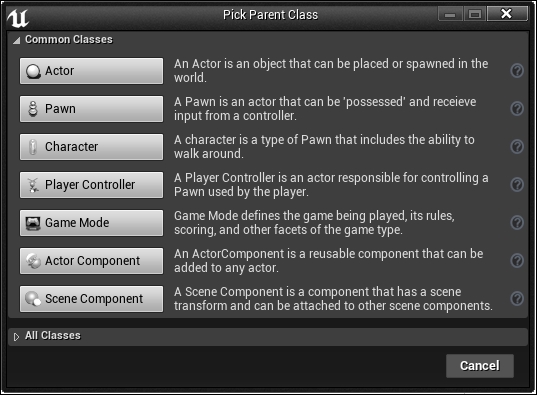
Here, we will choose the Parent Class of our Blueprint script. The editor shows us the Common Classes (we already saw them when previously talking about Blueprint classes); however, the list of parents that we can use is potentially unlimited. If you click on All Classes, in the left-hand side corner at the bottom, you can see a very long list containing all the objects that are available at that moment as a parent for your Blueprint.
Click on Actor and call it BP_Introduction.
Note
It is very important, even for a small project, to name your assets/scripts in a smart manner from the very beginning using a suffix in order to recognize and immediately find the required file even between hundreds of files.
Double-click on the BP_Introduction file to open it and we will finally arrive at our Blueprint Editor:

As you can see from the preceding image, the Blueprint Editor is divided into several panels. Each panel is independent; this means that they can be moved, resized, deleted, and duplicated in order to have a workspace that fits your choice.
Let's take a closer look at all of these sections in the following:
Menu Bar has the following options:
File: You can manage your Blueprint files from here. You can save and import other assets in the session, and manage source control. There is also a section dedicated to Blueprint, where you can compile, refresh, and compare your Blueprint revision in source control.
Edit: This is a typical edit menu. It can undo, redo, and modify history. You can also search for something in your Blueprint or change the editor settings and preferences.
Asset: Go here to open Content Browser or to check the references viewer of any of your assets.
View: View preferences can be set by this menu. Change the pin visibility or set the zoom.
Debug: Here, you can set the brake points and the watches for your Blueprint. We will go through the Blueprint debugging later in this chapter.
Window: If you accidentally close one of these tabs or you want to open another tab, you can do this going in this menu. All the Blueprint Editor specific tabs are contained. It is also possible to save or load a custom layout here.
Help: You can find useful information about Blueprint here or directly through the epic forum and Wiki.
The toolbar is displayed at the left-hand side top of the Blueprint Editor. Its buttons provide easy access to the common commands that are needed when editing Blueprints. This is a dynamic bar, which means that it provides different buttons, depending on which mode is active and which Blueprint type you are currently editing, as follows:

Compile: Every time you modify the script and want to run it, you need to compile. This button changes, depending on the state of your script. It shows if there is an error or a warning and if the script need to be recompiled.
Save: It saves the current Blueprint.
Find in CB: It shows Content Brower and highlights the selected Blueprint.
Search: It finds references to functions, events, variables, or pins in the current script.
Class Settings: It opens the Blueprint properties Details panel. These settings usually belong to the parent class of Blueprint. You can add Blueprint Interfaces to the Blueprint class here.
Class Defaults: It shows the default properties in the detail panel. Here, you can change the default properties of the new instances of this class.
Simulation: It starts the game in simulation mode.
Play / Stop / Pause: It manages the execution of the game in the selected environment such as mobile, standalone, and custom viewport.
Possess/Eject: It switches from Simulate in editor to play in editor mode.
Debug Filter: If you have two or more instances of this class in the game, you can choose which one to debug here.
In Viewport, you can view and manipulate your Blueprint's components:
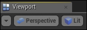
By default, you have a three-dimensional perspective view of your object. You can manipulate the settings of the Viewport using the buttons on the top-left corner. The first button allows you to switch between Perspective and the orthographic view, the second one sets how you see the object if it is Lit (rendered with light), Unlit (rendered without light) or in simple Wireframe instead.
The right-hand top series of buttons gives you some useful tools in order to manipulate your object:
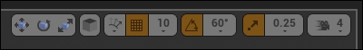
Select and translate / rotate / scale object: If one of these is selected, the corresponding three axis images appear on the pivot point of the object and you are allowed to move, rotate, or scale the object in one or all its axis.
Toggle Coordinate System: This button toggles the coordinate system between world and the local (object-related) system.
Surface snapping: This button toggles surface snapping, it enables an object to snap in a surface when possible.
Snap to the grid: This button toggles whenever the object snap to the grid or not.
Snap size: This button sets the accuracy of the snapping.
Rotation snapping: This button toggles the snap through a rotation grid.
Rotation size: This button sets the rotation-snap angle.
Scale snapping: This button toggles snapping object through a scale grid.
Scale size: This button sets the scale snap value.
Camera Speed: This button sets the speed of the camera when it is moving in the viewport with values between 1 to 8.
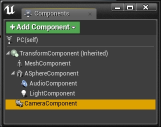
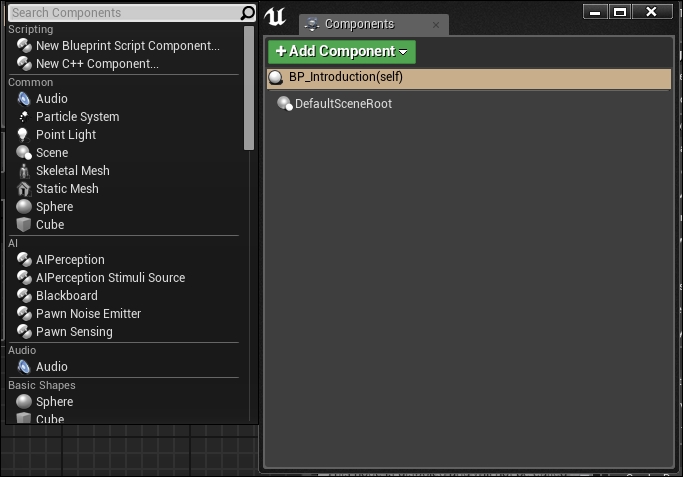
In the Components panel, you can find all the components of your Blueprint that are shown in a hierarchy form. A component is a piece of functionality that can be added to an Actor. Components cannot exist by themselves; however, when added to an Actor, the Actor will have access to the component and use the functionality provided by it:
In this panel, you can add/remove and manage your components. Each component has its own specific purpose and combining them allows you to create almost anything that you need.
CapsuleComponent, for example, provides collision geometry to the Actor. MovementComponent controls the movement, AudioComponent enables the Actor to emit sound, and so on.
Components added in the component list can also be assigned to instance variables, providing them access in the graphs editor.
In order to add a component to Blueprint, you can click on the Add Component button and select the component from its menu, as shown in the following image:
Components can also be added by dragging and dropping them from Content Browser in the Components panel.
Each component is placed at the location of the instance by default. However, they can be transformed, rotated, and scaled if necessary in either the Details panel or the Viewport, as we saw earlier.
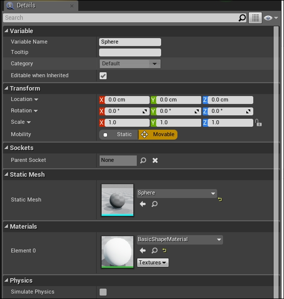
The Details panel contains information, utilities, and functions that are specific to the current selection in the Viewport or the content panel.
It contains all the editable properties of the selected object (such as the Transform parameters to move, rotate, and scale it):
At the very top, you find the search filter. This allows you to quickly find the property that you need (very handy when you have a long list of properties).
The Property Matrix button will open the Property Matrix grid. It is a special tool that allows easy bulk editing and value comparison for a large number of objects or Actors. It displays a configurable set of properties for a collection of objects as columns in a table view that can be sorted on any column. The Property Matrix grid also provides a standard property editor that displays all the properties for the current selection set in the table view.
The display filter icon allows you to filter the properties according to your need.
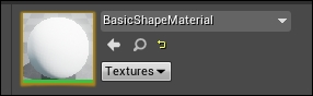
Some properties have three buttons. They allow you to open the selected property in Content Browser, attach the property from the selected one in Content Browser, or revert the property to default:
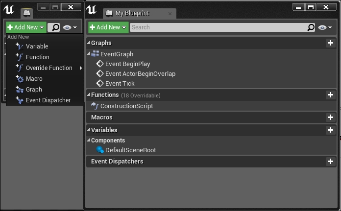
The My Blueprint panel shows all the Graphs, Functions, Macros, Variables, and Event Dispatchers contained in your Blueprint, including component instance variables that are added in the component list or variables that are created by promoting a value to a variable in the graph editor.
By default, your Blueprint contains one EventGraph and one ConstructionScript for your Functions but you can add any Graph, Variable, or function you might need by the Add New button:
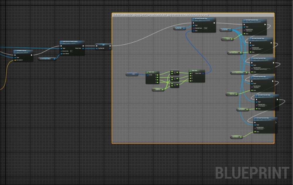
The graph editor panel is the heart of the Blueprint system. It is here that you will create your network of nodes and thanks to their wires, your game lives:
First of all, this table gives you some handy shortcuts for your movements in the graph.
Note
A smart usage of these shortcuts can save a lot of time when developing your projects. Try to memorize this table and always use the shortcuts when possible.
|
Control |
Action |
|---|---|
|
Right-click + Drag |
Pans the graph |
|
Mouse Scroll |
Zooms the graph |
|
Right-click |
Opens context menu |
|
Click on node |
Selects the node |
|
Click + Drag in the empty space |
Selects the nodes in the marquee select box |
|
Ctrl + Click + Drag in the empty space |
Toggles selection of the nodes in the marquee select box |
|
Shift + Click + Drag in the empty space |
Adds the nodes in the marquee select box to the current selection |
|
Click + Drag on node |
Moves node |
|
Click + Drag from pin to pin |
Wires the pins together |
|
Ctrl + Click + Drag from pin to pin |
Moves the wires from the origin pin to the destination pin |
|
Click + Drag from pin to the empty space |
Brings up the context menu, showing only relevant nodes. Wires the original pin to a compatible pin on the created node |
|
Click + Drag + C on the empty space |
Adds a comment box containing the selected nodes |
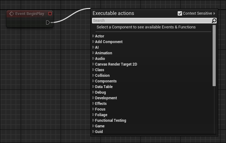
To add a new node to the graph, you can use the two methods explained in the table (right-click on the empty space or drag any pin from an existing node) and you can also drag and drop any asset from Content Browser to the graph editor. It will automatically add the corresponding node to the graph, as follows:
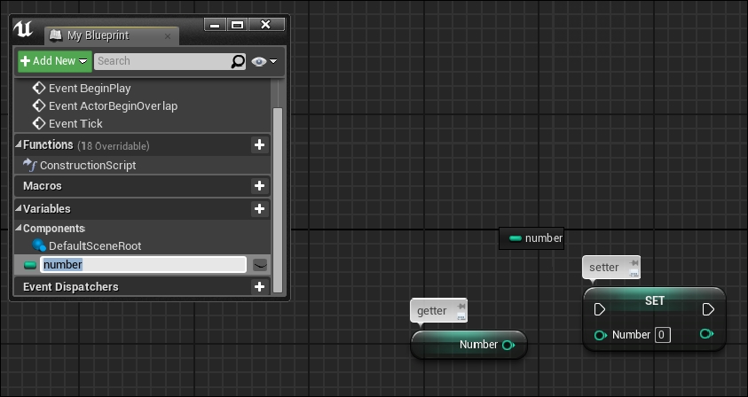
You can also drag and drop any Variables from the My Blueprint panel to the graph in order to automatically add its correspondent getter or setter (by selecting the desired node from the pop-up window that appears or by holding control for a getter or Alt for a setter) as shown in the following image:
You can find the same behavior seen in the Blueprint graph editor exhibited in the Construction Script Editor and in the Macros Graph Editor.
Let's now check the graph editor in deep: which variables are accepted and what are the nodes and pins that we just introduced.
Under Unreal, there are different types of variables: typical data types, such as Boolean, Integer, Float, and so on, and more complex reference types, such as objects, Actors, and custom classes. Each type has a unique color for easy identification, as shown in the following table:


Apart from these default data types, there are tons of other custom data types and we will see how to create our custom ones further in this book. These types can be regrouped in five categories, as follows:
Structure: Struct (value) types. A structure is a container of custom variables. It is used to group related variables in a single entity in order to simplify data combining and data management.
References to objects or Actors: As the name suggests, these data types are references of any object/actor in the game. They are useful when we want to communicate between two different Blueprint classes.
References to interfaces: They are the same as object pointers; however, they are referred to as interfaces objects.
References to classes: Similar to object references, this type of variable contains references to a class. The main difference is that this type points to the default class, while the object reference points to a single instance of this particular class in the game.
Enumeration: An enumerator is basically a byte variable that, instead of numbers, has a human-readable list of names. It can be used to store any kind of object state or type (Game States, tree types, weapon types, player states, and so on).
A node is an object that can perform a unique function, such as variable holder, event, math calculation, flow control operation, and so on. However, the way in which nodes are created and used is common to all nodes. This helps the user during the process of the graph creation.
A node has a common layout that we can find in any kind of node that we create, as follows:
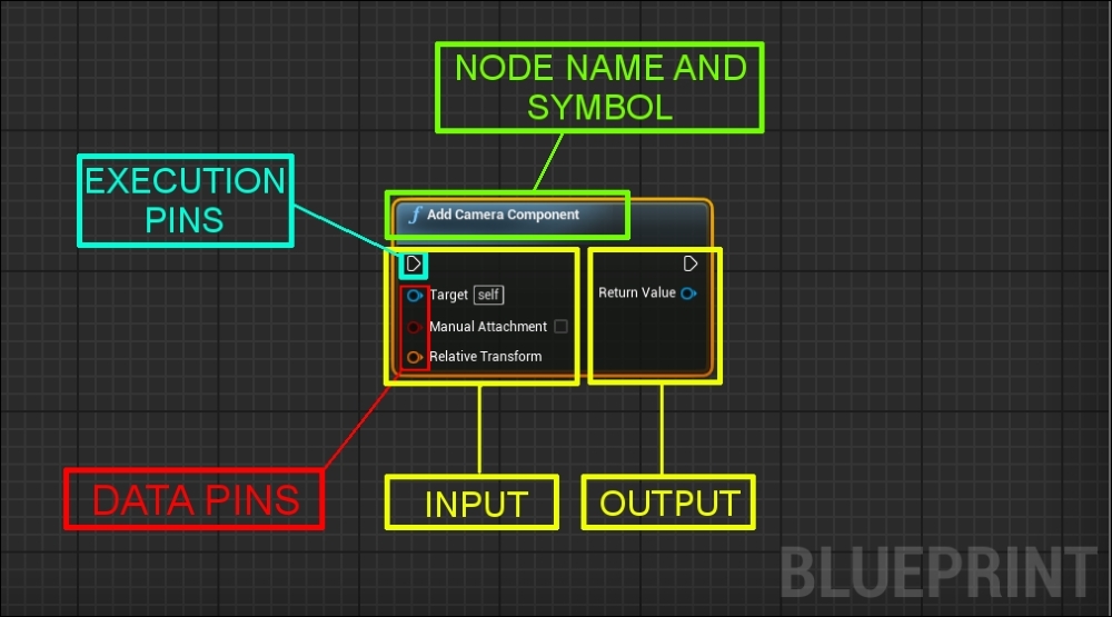
In the preceding image, we can notice the following: on the top we find his name and a symbol. Name, symbol, and color are self-explanatory and help the user to identify the node's behavior quickly, even if it is the first time that he is using it. In the preceding image, f means function, typically with a blue background, and the title suggests that this node is a function that will Add Camera Component to a target when called.
On the left-hand side of the node, we find the INPUT pins, and on the right-hand side, we find the OUTPUT pins. We can find nodes with only input (or output) pins; however, their position is unequivocal, as follows:
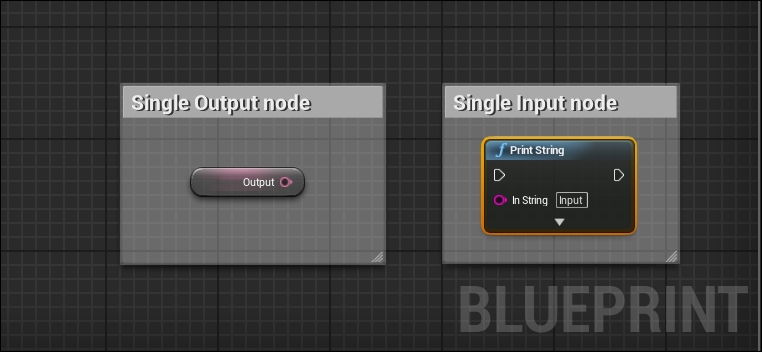
There are two main types of pins, execution pins and data pins, as follows:
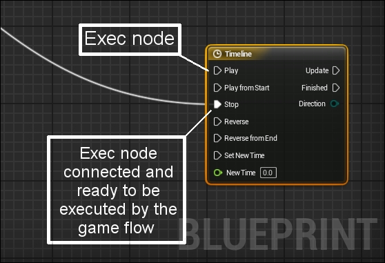
Execution pins are used to connect nodes together in order to create a flow of execution. A node is executed when its input execution pin is activated by another node. Once execution of the node completes, it activates its output execution pin to continue the flow of execution. Usually, there is only a single input and output execution pin (as functions only have one entry point and one exit point); however, other types of nodes can have multiple input or output execution pins, allowing different behavior depending on which pin is activated. For example, Timeline has multiple input execution pins to call Play, Stop, Reverse, and so on, and multiple output pins in order to call a custom function each time when each time loop is finished.
Data pins are used to put the data in a node or receive data from a node. Data pins are type-specific and can be wired to variables or other data pins of the same type. Unreal helps us to recognize the different types of variable, not only with the name, but also with its color. Their color is unique and common in all the tools of Unreal, not only in Blueprint. As execution pins, data pins are also displayed as an outline when not wired to anything and solid when wired.
When developing your Blueprints, you will soon find that at times something is not working as you expected. To diagnose these problems, Unreal Engine 4 gives you a powerful debugger system that allows you to see your Blueprint script flow in real time, as follows:
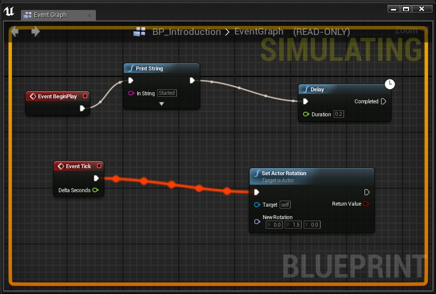
When you play or simulate in the editor, you can see the pulsating active wires as your script gets executed in your graph editor.
The debugger system is attached to the first instance of your Blueprint class that the editor finds in your level (alphabetic order) as soon as you play or simulate your game. If you have more than one instance and you want to specify which one to debug, you can select it from the toolbar.
You can set a Breakpoint in a node: when added you can play your game and when the simulation reaches that node, the game will pause and jump to that node in your graph so that you can step through your script to see where the issues are occurring.
To add a Breakpoint to your Blueprint, right-click on any execution node and choose Add breakpoint. You can also toggle the Breakpoint of a selected node by pressing F9:
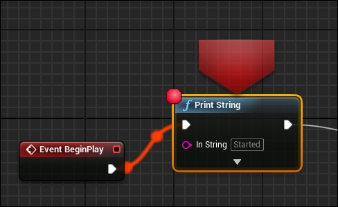
When a Breakpoint has been added to a node, a red circle will appear in the left-hand top corner of the node. This means that, as soon as the gameplay reaches that node, the game will pause and focus on this node.
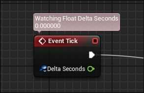
Another debugging feature is Watch Values. You can set any variable in your Blueprint to be able to see any variation of it in real time while the game is running. This is an important tool that helps you to find any logical error due to wrong calculations and human mistakes.
To set a value to be watched, right-click on a variable in your graph and select Watch this value. A floating text bubble will appear above of the variable, showing the value of this variable being changed while the game is executed, as follows:
From the Window tab, in the menu bar, you can open Blueprint Debugger. This panel shows all the watched variables or Breakpoint assigned. You can add multiple Blueprint debugger tabs by holding Shift and clicking on Actor in your scene:
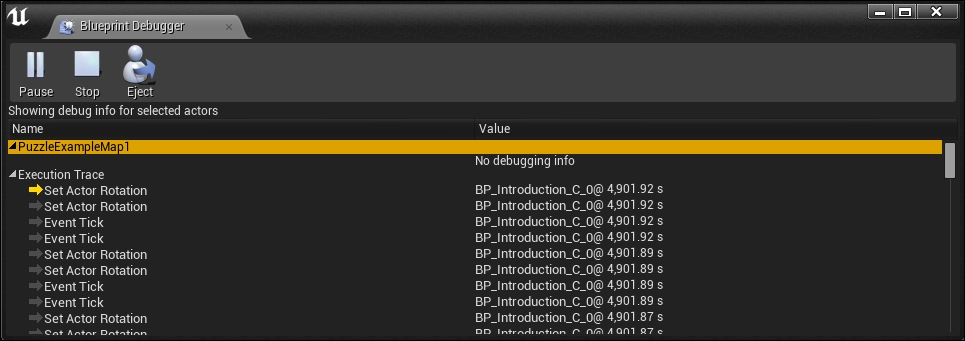
The lower section of the debugger is called Execution Trace, this will become populated as soon as you play or simulate in the editor and show all the executed commands in the order in which they were issued (the top one as the most recent).