
Sensors and actuators
The MCU and SoC-based ECUs discussed in the previous sections would be of very little use if it were not for the sensors that feed into their control algorithms and the actuators that are driven by the output of those algorithms. Sensors and actuators enable numerous vehicle functions that enhance both the driver experience and safety aspects, such as adaptive cruise control, automatic emergency braking, and more. When it comes to sensing, modern vehicles may contain upward of 100 sensors both embedded within the ECUs as well as within the vehicle’s body. Sensors transform a variety of physical conditions, including temperature, pressure, speed, and location, into analog or digital data output.
Understanding the physical properties of the sensor and its vehicle interfaces allows us to determine how it can be affected by a cyberattack. In the following subsection, we will sample a variety of sensors to gain a perspective on how they sense inputs and the interfaces by which they transmit and receive data:
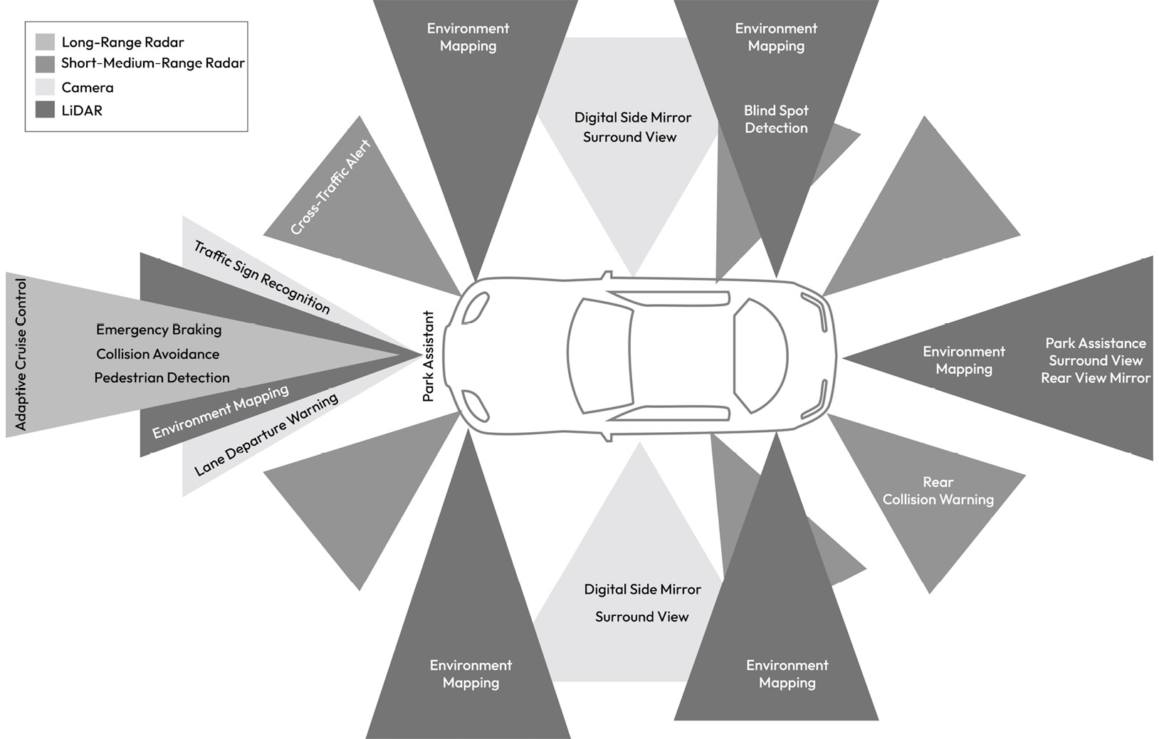
Figure 1.19 – Sensors mapped to ADAS functions providing 360-degree sensing capability
Sensor types
The sensors shown in Figure 1.19, in addition to a sample of internal sensors, are described here:
- Cameras: These enable a range of vehicle functions, such as digital rear-view mirrors, traffic sign recognition, and a surrounding view on the center display. A camera sensor produces raw image data of the surroundings by detecting light on a photosensitive surface (image plane) using a lens placed in front of the sensor. Camera data is then processed by the receiving ECU to produce the image data formatted for the camera applications. Typically, an image resolution of 8 megapixels is supported with a frame rate of up to 60 FPS. In most cases, the raw image data is serialized from the sensor over the GMSL link and deserialized by the host ECU with data transfers of up to 6 GB per second. A separate control channel is typically supported to configure and manage the sensor using a low-speed communication link such as I2C. Certain specialized cameras produce classified object information such as lane, car, and pedestrian. In all cases, attacks against cameras can impact the vehicle’s ability to correctly identify objects, which can have a serious safety impact. Additionally, user privacy can be violated if the camera data is illegally accessed.
- Light Detection and Ranging (LiDAR): This is a remote sensing technology based on the principle of emitting pulses of laser light and measuring the reflection of target objects. The interval taken between the emission and reception of the light pulse enables the estimation of the object’s distance. As the LiDAR scans its surroundings, it generates a 3D representation of the scene, also known as a point cloud. LiDAR sensors are used in object detection algorithms and can support the transmission of either raw or pre-processed point cloud data. Such sensors typically interface to the host ECU through a 1000Base-T1 Ethernet link. Attacks against LiDAR can impact the vehicle’s ability to detect objects, which can have a safety impact.
- Ultrasonic sensors: These are electronic devices that measure the distance of a target object by emitting ultrasonic sound waves and converting the reflected sound into an electrical signal. Ultrasonic waves are sound waves transmitted at frequencies higher than those audible to humans and have two main components: the transmitter (which emits the sound using piezoelectric crystals) and the receiver (which transforms the acoustic signal into an electrical one). Ultrasonic sensors typically interface with the host ECU via CAN. Attacks against the ultrasonic sensors can impact the vehicle’s ability to detect objects during events such as parking, which can have a safety impact.
- Radio Detection and Ranging (Radar): This is based on the idea of emitting EM waves within the region of interest and receiving dispersed waves (or reflections) from targets, which are then processed to determine the object range information. This allows the sensor to determine the relative speed and position of identified obstacles using the Doppler property of EM waves. A radar sensor’s resolution is much more coarse than a camera’s and typically interfaces to the host ECU via CAN or Ethernet. Like LiDAR, Radar is used in autonomous driving applications, so attacks impacting its data have implications for vehicle safety.
- GNSS sensors: These use their antennas to receive satellite-based navigation signals from a network of satellites that orbit the Earth to provide position, velocity, and timing information. These sensors typically interface with the host ECU via CAN or UART. Attacks on GNSS sensors can impact the vehicle’s localization ability, which is critical for determining the vehicle’s location within a map to establish a sense of the road and buildings. Also, GNSS input is necessary for receiving global time, which, if compromised, can interfere with the vehicle’s ability to get a reliable time source.
- Temperature sensors: These are used for sensing temperature, typically using a thermistor, which utilizes the concept of negative temperature coefficient. A thermistor with a negative temperature coefficient experiences lower resistance as its temperature increases, which allows you to correlate a change in temperature to a change in the electric signal flowing through the thermistor. Other techniques besides a thermistor exist, such as infrared (IR) sensors, which detect the IR energy emitted by an object and transmit a signal to the MCU for processing. Temperature sensors are used in many automotive applications both inside the MCUs and SoCs as well as on the PCB board itself. They are essential for temperature monitoring to satisfy safety requirements. Temperature sensors embedded within the MCU typically provide temperature readings through a simple register read operation, while external temperature sensors can be interfaced to the MCU via general-purpose input/output (GPIO) pins, analog-to-digital converters (ADCs), or I2C. Attacks on temperature sensors can impact the ECU’s ability to monitor its temperature, potentially leading to undetected overheating situations, which can be hazardous.
- Vehicle dynamics sensors: These enable active and passive safety ECUs to determine the vehicle’s motion state, which factors into the algorithms for controlling steering, braking, and airbag deployment. Attacks on any one of these sensors will have a direct safety impact as the control algorithms consuming their data would be making erroneous calculations that would likely result in an unsafe control action. Here is a sample of the most common sensors that are used within this domain:
- Inertial measurement units (IMUs) sense the physical effects of motion along six dimensions: yaw, roll, and pitch rate as well as lateral, longitudinal, and vertical accelerations. This helps the vehicle determine when it is experiencing hazardous events, such as slipping on ice or roll-over. IMUs leverage MEMS technology to sense acceleration through the capacitive change in the micromechanical structures of the sensor. They are typically interfaced with the host ECU via CAN.
- The steering angle sensor design is typically based on Giant Magnetoresistance (GMR) technology. It is positioned onto the steering shaft to measure the steering angle value. The sensor outputs both the steering angle value and steering angle velocity over CAN. Wheel speed sensors use a Hall-sensing element in a changing magnetic field to produce an alternating digital output signal whose frequency is correlated to the wheel speed. The wheel speed sensor is typically hardwired to the host ECU, normally the EBCM.
- The brake pedal sensor, also known as the angular position sensor, is normally based on a magnetic field sensor, which enables contactless pedal angle measurement. This is typically used in the regenerative braking of hybrid and electric vehicles. This sensor is hardwired to the host ECU, normally the EBCM.
The accelerator pedal sensor, also known as the rotary position sensor, uses a magnetic rotary sensor with a Hall element to measure the angular position. The sensor is hardwired to the host ECU, normally the ECM. In addition to sensors mounted inside the vehicle, a wide range of sensors exist that are integrated directly within vehicle electromechanical components such as the engine’s mass air flow rate sensor, which is used for electronic fuel injection. Another important engine sensor is the exhaust gas oxygen sensor, which enables the exhaust emissions catalyst to operate correctly. Attacks against these types of sensors can have environmental impacts due to their role in emissions control.
Understanding the sensors that are used within your vehicle, their physical characteristics, and the method by which they are interfaced with ECUs is important for understanding the threats that may apply to those sensors. Therefore, you are encouraged to make an inventory of all the sensors related to your ECU as preparation for the next chapters when we study threats impacting sensors.
The sensor inputs to the control algorithms of an ECU would be of very little value if not for the components that convert the ECU output into physical action. In the next subsection, we will focus on these types of components and learn how they can be controlled by the ECU.
Actuators
An actuator is a component that can be electronically controlled to move a mechanism or a system. It is operated by a source of energy, such as an electric current, hydraulic fluid pressure, or pneumatic pressure, which is then converted into motion. The ECU contains the electronic components necessary to interface with the actuators and apply the software-driven control algorithms. Understanding how actuators are controlled and the effect they can have if misused is important for vehicle cybersecurity. Here’s a sample of some of the common actuators that we expect to find in a vehicle:
- AC servo motors: These are electrical devices that are driven by an ECU to accurately rotate mechanisms within the vehicle. These motors are used in many use cases within the vehicle, such as assisting steering by controlling the motion of the steering column, as demanded by the EPS.
- Brushless DC motors: In powertrain applications, brushless DC motors can be found in the shifting function of the transmission, as well as the torque distribution controller in transfer cases and differentials. Several possible interfaces exist to control these motors, such as Pulse Width Modulation (PWM) and CAN.
- Electric window lift drives: These enable the opening and safe closing of windows. They typically offer self-locking gear units to prevent windows from being forced open from the outside. These drives are normally interfaced with the BCM through LIN.
- Seat drives: These use one - or two-stage gear motors to control seat adjustment. It is normally controlled by the BCM through LIN.
- Sunroof drive: It produces high torque to control the sunroof’s position through a motor and gear system that is controlled by the BCM.
- Fuel pump: This is electrically controlled by the ECM to provide the engine with fuel at the required pressure.
- Injectors: These are solenoid-equipped injection nozzles that the ECM manages. The ECM determines the basic fuel injection time based on intake air volume and engine RMP, as well as the corrective fuel injection time based on engine coolant temperature and the feedback signal from the oxygen sensor during closed-loop control.
While actuators are normally not directly accessible by an attacker, it is important to understand the impacts of attacks targeting them and whether feasible attack paths exist to reach them.
Now that we have explored the various ECUs, sensors/actuators, and networking technologies that enable their communication, we will consider the different topologies that shape how these components are interconnected and used.