
Before we dive into OpenGL ES programming, it's very important to understand how the underlying architecture is stacked. There are two types of OpenGL ES architectures: fixed and programmable pipelines. This section will provide you a simple overview of these architectures; this overview will also help us to grasp the technical jargon of computer graphics terminology.
The following image shows the OpenGL ES 1.1 fixed function pipeline architecture. It also provides the sequence of events from the moment input data is sent to the rendering engine to output an image generated on the screen.
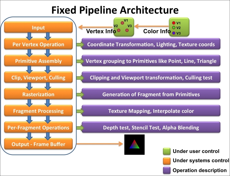
The Input refers to the supply of raw data and drawing information required by the rendering engine to draw an object on the screen. For example, the preceding image shows three vertices, and three color data are provided to the graphics engine as raw data. In addition, we specified the engine that will draw this raw data in the form of a triangle.
In Per Vertex Operation, transformations on input vertex coordinates are performed. Each geometrical input vertex is transformed on the basis of the camera view or object translation.
More specifically, at this stage, the modeling transformation is performed to convert object coordinates to world space coordinates. Further, these coordinates are converted to eye space coordinates by view transformation. Light information and texture coordinates are also calculated according to these transformations for all vertices. The second chapter, OpenGL ES 3.0 essentials, covers all the technical jargon that we have used for transformation in this section under Transformation with the model, view, and projection analogies recipe.
The Primitive assembly takes all the transformed coordinates from the previous stage and arranges them as per the specified draw or the primitive type (point, line, triangle) information provided at the input stage. For example, we supplied three vertices and instructed the engine to render them as a triangle. There are basically three types of primitives available in OpenGL ES: point, line, and triangle (also the variants of line and triangle). These basic three primitives can be used to render any complex geometry.
In the Clip, Viewport, and Culling stages, the projection transformation is applied to generate clip space coordinates. In this, vertices that are outside the camera viewing volume are discarded. The resultant vertex coordinates are treated with the perspective division where normalize device coordinates are generated. Finally, viewport transformation is applied to normalize device coordinates to form screen space pixel coordinates. Faces are culled on the basis of the direction of the face, as specified to the graphics engine.
Rasterization is the process of converting transformed screen space primitives (point, line, and triangle) to discrete elements called fragments. The output of each fragment are screen coordinates and related attributes, such as color, texture coordinates, depth, and stencil.
The fragment processing stage processes each fragment generated in the rasterization stage. This stage processes the fragment appearance information using the color or texture information.
The per-fragment operations stage performs some important tests before rendering images on screen. It consists of:
The pixel ownership test: This is a test where pixel screen coordinates generated by the rasterization stage are tested to see whether they belong to the OpenGL ES context. For example, it may be possible that the rendering screen is overlaid with some text messages or obscured by other windows.
The scissor test: This stage ensures that fragments that are present outside the rectangle formed by four values of the scissor rectangle region should not be considered in rendering.
The stencil and depth test: This test checks the stencil and depth value to see whether the fragment needs to be discarded or not. For example, if two primitives are obscuring each other, the primitive fragment on top is kept by the OpenGL ES state. However, fragments belonging to the behind one will be discarded, irrespective of the rendering order.
Blending: This is a process of generating new color information, using the previous color specified earlier in the same color buffer location.
Dithering: This technique uses existing colors to create effects of other colors. For example, various shades of gray color can be produced using various patterns generated by white and black colors.
Unlike the fixed function pipeline, the programmable pipeline architecture provides the flexibility to modify some stages of the graphics pipeline. OpenGL ES 2.0 and 3.0 follows the programmable pipeline architecture. These stages are modified using special programs called shaders. The following image shows the programmable pipeline architecture for OpenGL ES 3.0. The architecture for 2.0 is also similar to the following image, except that it does not support a special stage called the Transform feedback. Transform feedback is a new stage introduced in OpenGL ES 3.0. This stage is responsible for capturing the processed vertex data buffer after the geometric shading stage. These programmable stages can be seen in the following figure with green boxes. Developers need to program the shader to render object using OpenGL ES 3.0.
The programmable pipeline architecture requires at least two shaders, namely, the vertex shader and the fragment shader to render geometry on screen. Without these shaders, rendering is not possible.
The vertex shader is the first shader in the programmable pipeline architecture. Its responsibility is to perform processing on vertex coordinates to produce coordinate transformations. In most cases, it's used to calculate clipped coordinates from the model, view, and projection information. An example of the vertex shader is as follows:
#version 300 es
in vec4 VertexPosition;
void main() {
  gl_Position = VertexPosition;
};
The fragment shader is the last shader that works on the pixel level; it uses the output data from the rasterization stage, which generates primitive fragments. This shader is responsible for calculating colors for each and every fragment rendering object on screen. The fragment shader is also capable of applying textures on the fragment shader. Here is an example of the fragment shader:
#version 300 es
precision mediump float;
out vec4 FragColor;
void main() {
  FragColor = vec4(0.0, 0.30, 0.60, 0.0);
};
The programmable pipeline architecture needs a special type of language to program shaders. This language is called the OpenGL ES Shading Language. In this book, we will use specifications of OpenGL ES Shading Language 3.0.