Book Image

Direct3D Rendering Cookbook

Book Image

Direct3D Rendering Cookbook

Overview of this book

Table of Contents (19 chapters)
Direct3D Rendering Cookbook
Credits
About the Author
About the Reviewers
www.PacktPub.com
Preface
Further Reading
Index

Introduction


Direct3D is the component of the DirectX API dedicated to exposing 3D graphics hardware to programmers on Microsoft platforms including PC, console, and mobile devices. It is a native API allowing you to create not only 3D graphics for games, scientific and general applications, but also to utilize the underlying hardware for General-purpose computing on graphics processing units (GPGPU).

Programming with Direct3D can be a daunting task, and although the differences between the unmanaged C++ API and the managed .NET SharpDX API (from now on referred to as the unmanaged and managed APIs respectively) are subtle, we will briefly highlight some of these while also gaining an understanding of the graphics pipeline.

We will then learn how to get started with programming for Direct3D using C# and SharpDX along with some useful debugging techniques.

Components of Direct3D

Direct3D is a part of the larger DirectX API comprised of many components that sits between applications and the graphics hardware drivers. Everything in Direct3D begins with the device and you create resources and interact with the graphics pipeline through various Component Object Model (COM) interfaces from there.

Device

The main role of the device is to enumerate the capabilities of the display adapter(s) and to create resources. Applications will typically only have a single device instantiated and must have at least one device to use the features of Direct3D.

Unlike previous versions of Direct3D, in Direct3D 11 the device is thread-safe. This means that resources can be created from any thread.

The device is accessed through the following interfaces/classes:

  • Managed: Direct3D11.Device (Direct3D 11), Direct3D11.Device1 (Direct3D 11.1), and Direct3D11.Device2 (Direct3D 11.2)

  • Unmanaged: ID3D11Device, ID3D11Device1, and ID3D11Device2

    Note

    Each subsequent version of the COM interface descends from the previous version; therefore, if you start with a Direct3D 11 device instance and query the interface for the Direct3D 11.2 implementation, you will still have access to the Direct3D 11 methods with the resulting device reference.

One important difference between the unmanaged and managed version of the APIs used throughout this book is that when creating resources on a device with the managed API, the appropriate class constructor is used with the first parameter passed in being a device instance, whereas the unmanaged API uses a Create method on the device interface.

For example, creating a new blend state would look like the following for the managed C# API:

var blendState = new BlendState(device, desc);

And like this for the unmanaged C++ API:

ID3D11BlendState* blendState;
HRESULT r = device->CreateBlendState(&desc, &blendState);

Tip

Downloading the example code

You can download the example code files for all Packt books you have purchased from your account at http://www.packtpub.com. If you purchased this book elsewhere, you can visit http://www.packtpub.com/support and register to have the files e-mailed directly to you.

Further, a number of the managed classes use overloaded constructors and methods that only support valid parameter combinations, relying less on a programmer's deep understanding of the Direct3D API.

With Direct3D 11, Microsoft introduced Direct3D feature levels to manage the differences between video cards. The feature levels define a matrix of Direct3D features that are mandatory or optional for hardware devices to implement in order to meet the requirements for a specific feature level. The minimum feature level required for an application can be specified when creating a device instance, and the maximum feature level supported by the hardware device is available on the Device.FeatureLevel property. More information on feature levels and the features available at each level can be found at http://msdn.microsoft.com/en-us/library/windows/desktop/ff476876(v=vs.85).aspx.

Device context

The device context encapsulates all rendering functions. These include setting the pipeline state and generating rendering commands with resources created on the device.

Two types of device context exist in Direct3D 11, the immediate context and deferred context. These implement immediate rendering and deferred rendering respectively.

The interfaces/classes for both context types are:

  • Managed: Direct3D11.DeviceContext, Direct3D11.DeviceContext1, and Direct3D11.DeviceContext2

  • Unmanaged: ID3D11DeviceContext, ID3D11DeviceContext1, and ID3D11DeviceContext2

Immediate context

The immediate context provides access to data on the GPU and the ability to execute/playback command lists immediately against the device. Each device has a single immediate context and only one thread may access the context at the same time; however, multiple threads can interact with the immediate context provided appropriate thread synchronization is in place.

All commands to the underlying device eventually must pass through the immediate context if they are to be executed.

The immediate context is available on the device through the following methods/properties:

  • Managed: Device.ImmediateContext, Device1.ImmediateContext1, and Device2.ImmediateContext2

  • Unmanaged: ID3D11Device::GetImmediateContext, ID3D11Device1::GetImmediateContext1, and ID3D11Device2::GetImmediateContext2

Deferred context

The same rendering methods are available on a deferred context as for an immediate context; however, the commands are added to a queue called a command list for later execution upon the immediate context.

Using deferred contexts results in some additional overhead, and only begins to see benefits when parallelizing CPU-intensive tasks. For example, rendering the same simple scene for the six sides of a cubic environment map will not immediately see any performance benefits, and in fact will increase the time it takes to render a frame as compared to using the immediate context directly. However, render the same scene again with enough CPU load and it is possible to see some improvements over rendering directly on the immediate context. The usage of deferred contexts is no substitute for a well written engine and needs to be carefully evaluated to be correctly taken advantage of.

Multiple deferred context instances can be created and accessed from multiple threads; however, each may only be accessed by one thread at a time. For example, with the deferred contexts A and B, we can access both at the exact same time from threads 1 and 2 provided that thread 1 is only accessing deferred context A and thread 2 is only accessing deferred context B (or vice versa). Any sharing of contexts between threads requires thread synchronization.

The resulting command lists are not executed against the device until they are played back by an immediate context.

Note

If a device is created with the single-threaded device creation flag, an error will occur if you attempt to create a deferred context. The result of accessing Direct3D interfaces from multiple threads is also undefined.

A deferred context is created with:

  • Managed: new DeviceContext(device)

  • Unmanaged: ID3D11Device::CreateDeferredContext

Command lists

A command list stores a queue of Direct3D API commands for deferred execution or merging into another deferred context. They facilitate the efficient playback of a number of API commands queued from a device context.

A command list is represented by the ID3D11CommandList interface in unmanaged C++ and the Direct3D11.CommandList class in managed C# with SharpDX. They are created using:

  • Managed: DeviceContext.FinishCommandList

  • Unmanaged: ID3D11DeviceContext::FinishCommandList

Command lists are played back on the immediate context using:

  • Managed: DeviceContext.ExecuteCommandList

  • Unmanaged: ID3D11DeviceContext::ExecuteCommandList

Tip

Trying to execute a command list on a deferred context or trying to create a command list from an immediate context will result in an error.

Swap chains

A swap chain facilitates the creation of one or more back buffers. These buffers are used to store rendered data before being presented to an output display device. The swap chain takes care of the low-level presentation of this data and with Direct3D 11.1, supports stereoscopic 3D display behavior (left and right eye for 3D glasses/displays).

If the output of rendering is to be sent to an output connected to the current adapter, a swap chain is required.

Swap chains are part of the DirectX Graphics Infrastructure (DXGI) API, which is responsible for enumerating graphics adapters, display modes, defining buffer formats, sharing resources between processes, and finally (via the swap chain) presenting rendered frames to a window or output device for display.

A swap chain is represented by the following types:

  • Managed: SharpDX.DXGI.SwapChain and SharpDX.DXGI.SwapChain1

  • Unmanaged: IDXGISwapChain and IDXGISwapChain1

States

A number of state types exist to control the behavior of some fixed function stages of the pipeline and how samplers behave for shaders.

All shaders can accept several sampler states. The output merger can accept both, a blend state and depth-stencil state, and the rasterizer accepts a rasterizer state. The types used are shown in the following table.

Managed type (SharpDX.Direct3D11)

Unmanaged type

BlendState

ID3D11BlendState

BlendState1

ID3D11BlendState1

DepthStencilState

ID3D11DepthStencilState

RasterizerState

ID3D11RasterizerState

RasterizerState1

ID3D11RasterizerState1

SamplerState

ID3D11SamplerState

Resources

A resource is any buffer or texture that is used as an input and/or output from the Direct3D pipeline. A resource is consumed by creating one or more views to the resource and then binding them to stages of the pipeline.

Textures

A texture resource is a collection of elements known as texture pixels or texels—which represent the smallest unit of a texture that can be read or written to by the pipeline. A texel is generally comprised of between one and four components depending on which format is being used for the texture; for example, a format of Format.R32G32B32_Float is used to store three 32-bit floating point numbers in each texel whereas a format of Format.R8G8_UInt represents two 8-bit unsigned integers per texel. There is a special case when dealing with compressed formats (Format.BC) where the smallest unit consists of a block of 4 x 4 texels.

A texture resource can be created in a number of different formats as defined by the DXGI format enumeration (SharpDX.DXGI.Format and DXGI_FORMAT for managed/unmanaged, respectively). The format can be either applied at the time of creation, or specified when it is bound by a resource view to the pipeline.

Hardware device drivers may support different combinations of formats for different purposes, although there is a list of mandatory formats that the hardware must support depending on the version of Direct3D. The device's CheckFormatSupport method can be used to determine what resource type and usage a particular format supports on the current hardware.

Note

Textures do not just store image data. They are used for information, such as height-maps, displacement-maps, or for any data structure that needs to be read or written within a shader that can benefit from the speed benefits of hardware support for textures and texture sampling.

Types of texture resources include:

  • 1D Textures and 1D Texture Arrays

  • 2D Textures and 2D Texture Arrays

  • 3D Textures (or volume textures)

  • Unordered access textures

  • Read/Write textures

The following table maps the managed to unmanaged types for the different textures.

Managed type (SharpDX.Direct3D11)

Unmanaged type

Texture1D

ID3D11Texture1D

Texture2D

ID3D11Texture2D

Texture3D

ID3D11Texture3D

Arrays of 1D and 2D textures are configured with the subresource data associated with the description of the texture passed into the appropriate constructor. A common use for texture arrays is supporting Multiple Render Targets (MRT).

Resource views

Before a resource can be used within a stage of the pipeline it must first have a view. This view describes to the pipeline stages what format to expect the resource in and what region of the resource to access. The same resource can be bound to multiple stages of the pipeline using the same view, or by creating multiple resource views.

It is important to note that although a resource can be bound to multiple stages of the pipeline, there may be restrictions on whether the same resource can be bound for input and output at the same time. As an example, a Render Target View (RTV) and Shader Resource View (SRV) for the same resource both cannot be bound to the pipeline at the same time. When a conflict arises the read-only resource view will be automatically unbound from the pipeline, and if the debug layer is enabled, a warning message will be output to the debug output.

Using resources created with a typeless format, allows the same underlying resource to be represented by multiple resource views, where the compatible resolved format is defined by the view. For example, using a resource with both a Depth Stencil View (DSV) and SRV requires that the underlying resource be created with a format like Format.R32G8X24_Typeless. The SRV then specifies a format of Format.R32_Float_X8X24_Typeless, and finally the DSV is created with a format of Format.D32_Float_S8X24_UInt.

Some types of buffers can be provided to certain stages of the pipeline without a resource view, generally when the structure and format of the buffer is defined in some other way, for example, using state objects or structures within shader files.

Types of resource views include:

  • Depth Stencil View (DSV),

  • Render Target View (RTV),

  • Shader Resource View (SRV)

  • Unordered Access View (UAV)

  • Video decoder output view

  • Video processor input view

  • Video processor output view

The following table shows the managed and unmanaged types for the different resource views.

Managed type (SharpDX.Direct3D11)

Unmanaged type

DepthStencilView

ID3D11DepthStencilView

RenderTargetView

ID3D11RenderTargetView

ShaderResourceView

ID3D11ShaderResourceView

UnorderedAccessView

ID3D11UnorderedAccessView

VideoDecoderOutputView

ID3D11VideoDecoderOutputView

VideoProcessorInputView

ID3D11VideoProcessorInputView

VideoProcessorOutputView

ID3D11VideoProcessorOutputView

Buffers

A buffer resource is used to provide structured and unstructured data to stages of in the graphics pipeline.

Types of buffer resources include:

  • Vertex buffer

  • Index buffer

  • Constant buffer

  • Unordered access buffers

    • Byte address buffer

    • Structured buffer

    • Read/Write buffers

    • Append/Consume structured buffers

All buffers are represented by the SharpDX.Direct3D11.Buffer class (ID3D11Buffer for the unmanaged API). The usage is defined by how and where it is bound to the pipeline. The following table shows the binding flags for different buffers:

Buffer type

Managed BindFlags flags

Unmanaged D3D11_BIND_FLAG flags

Vertex buffer

VertexBuffer

D3D11_BIND_VERTEX_BUFFER

Index buffer

IndexBuffer

D3D11_BIND_INDEX_BUFFER

Constant buffer

ConstantBuffer

D3D11_BIND_CONSTANT_BUFFER

Unordered access buffers

UnorderedAccess

D3D11_BIND_UNORDERED_ACCESS

Unordered access buffers are further categorized into the following types using an additional option/miscellaneous flag within the buffer description as shown in the following table:

Buffer type

Managed ResourceOptionFlags flags

Unmanaged D3D11_RESOURCE_MISC_FLAG flags

Byte address buffer

BufferAllowRawViews

D3D11_RESOURCE_MISC_BUFFER_ALLOW_RAW_VIEWS

Structured buffer

BufferStructured

D3D11_RESOURCE_MISC_BUFFER_STRUCTURED

Read/Write buffers

Either use Byte address buffer / Structured buffer and then use RWBuffer or RWStructuredBuffer<MyStruct> instead of Buffer and StructuredBuffer<MyStruct> in HLSL.

Append/Consume buffers

A structured buffer and then use AppendStructuredBuffer or ConsumeStructuredBuffer in HLSL. Use UnorderedAccessViewBufferFlags.Append when creating the UAV.

Shaders and High Level Shader Language

The graphics pipeline is made up of fixed function and programmable stages. The programmable stages are referred to as shaders, and are programmed using small High Level Shader Language (HLSL) programs. The HLSL is implemented with a series of shader models, each building upon the previous version. Each shader model version supports a set of shader profiles, which represent the target pipeline stage to compile a shader. Direct3D 11 introduces Shader Model 5 (SM5), a superset of Shader Model 4 (SM4).

An example shader profile is ps_5_0, which indicates a shader program is for use in the pixel shader stage and requires SM5.

Stages of the programmable pipeline

All Direct3D operations take place via one of the two pipelines, known as pipelines for the fact that information flows in one direction from one stage to the next. For all drawing operations, the graphics pipeline is used (also known as drawing pipeline or rendering pipeline). To run compute shaders, the dispatch pipeline is used (aka DirectCompute pipeline or compute shader pipeline).

Although these two pipelines are conceptually separate. They cannot be active at the same time. Context switching between the two pipelines also incurs additional overhead so each pipeline should be used in blocks—for example, run any compute shaders to prepare data, perform all rendering, and finally post processing.

Methods related to stages of the pipeline are found on the device context. For the managed API, each stage is grouped into a property named after the pipeline stage. For example, for the vertex shader stage, deviceContext.VertexShader.SetShaderResources, whereas the unmanaged API groups the methods by a stage acronym directly on the device context, for example, deviceContext->VSSetShaderResources, where VS represents the vertex shader stage.

The graphics pipeline

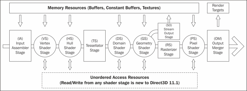
The graphics pipeline is comprised of nine distinct stages that are generally used to create 2D raster representations of 3D scenes, that is, take our 3D model and turn it into what we see on the display. Four of these stages are fixed function and the remaining five programmable stages are called shaders (the following diagram shows the programmable stages as a circle). The output of each stage is taken as input into the next along with bound resources or in the case of the last stage, Output Merger (OM), the output is sent to one or more render targets. Not all of the stages are mandatory and keeping the number of stages involved to a minimum will generally result in faster rendering.

Optional tessellation support is provided by the three tessellation stages (two programmable and one fixed function): the hull shader, tessellator, and domain shader. The tessellation stages require a Direct3D feature level of 11.0 or later.

As of Direct3D 11.1, each programmable stage is able to read/write to an Unordered Access View (UAV). A UAV is a view of a buffer or texture resource that has been created with the BindFlags.UnorderedAccess flag (D3D11_BIND_UNORDERED_ACCESS from the D3D11_BIND_FLAG enumeration).

Direct3D Graphics Pipeline

Input Assembler (IA) stage

The IA stage reads primitive data (points, lines, and/or triangles) from buffers and assembles them into primitives for use in subsequent stages.

Usually one or more vertex buffers, and optionally an index buffer, are provided as input. An input layout tells the input assembler what structure to expect the vertex buffer in.

The vertex buffer itself is also optional, where a vertex shader only has a vertex ID as input (using the SV_VertexID shader system value input semantic) and then can either generate the vertex data procedurally or retrieve it from a resource using the vertex ID as an index. In this instance, the input assembler is not provided with an input layout or vertex buffer, and simply receives the number of vertices that will be drawn. For more information, see http://msdn.microsoft.com/en-us/library/windows/desktop/bb232912(v=vs.85).aspx.

Device context commands that act upon the input assembler directly are found on the DeviceContext.InputAssembler property, for example, DeviceContext.InputAssembler.SetVertexBuffers, or for unmanaged begin with IA, for example, ID3D11DeviceContext::IASetVertexBuffers.

Vertex Shader (VS) stage

The vertex shader allows per-vertex operations to be performed upon the vertices provided by the input assembler. Operations include manipulating per-vertex properties such as position, color, texture coordinate, and a vertex's normal.

A vertex can be comprised of up to sixteen 32-bit vectors (up to four components each). A minimal vertex usually consists of position, color, and the normal vector. In order to support larger sets of data or as an alternative to using a vertex buffer, the vertex shader can also retrieve data from a texture or UAV.

A vertex shader is required; even if no transform is needed, a shader must be provided that simply returns vertices without modifications.

Device context commands that are used to control the vertex shader stage are grouped within the DeviceContext.VertexShader property or for unmanaged begin with VS, for example, DeviceContext.VertexShader.SetShaderResources and ID3D11DeviceContext::VSSetShaderResources, respectively.

Hull Shader (HS) stage

The hull shader is the first stage of the three optional stages that together support hardware accelerated tessellation. The hull shader outputs control points and patches constant data that controls the fixed function tessellator stage. The shader also performs culling by excluding patches that do not require tessellation (by applying a tessellation factor of zero).

Unlike other shaders, the hull shader consists of two HLSL functions: the patch constant function, and hull shader function.

This shader stage requires that the IA stage has one of the patch list topologies set as its active primitive topology (for example, SharpDX.Direct3D.PrimitiveTopology.PatchListWith3ControlPoints for managed and D3D11_PRIMITIVE_TOPOLOGY_3_CONTROL_POINT_PATCHLIST for unmanaged).

Device context commands that control the hull shader stage are grouped within the DeviceContext.HullShader property or for unmanaged device begin with HS.

Tessellator stage

The tessellator stage is the second stage of the optional tessellation stages. This fixed function stage subdivides a quad, triangle, or line into smaller objects. The tessellation factor and type of division is controlled by the output of the hull shader stage.

Unlike all other fixed function stages the tessellator stage does not include any direct method of controlling its state. All required information is provided within the output of the hull shader stage and implied through the choice of primitive topology and configuration of the hull and domain shaders.

Domain Shader (DS) stage

The domain shader is the third and final stage of the optional tessellation stages. This programmable stage calculates the final vertex position of a subdivided point generated during tessellation.

The types of operations that take place within this shader stage are often fairly similar to a vertex shader when not using the tessellation stages.

Device context commands that control the domain shader stage are grouped by the DeviceContext.DomainShader property, or for unmanaged begin with DS.

Geometry Shader (GS) stage

The optional geometry shader stage runs shader code that takes an entire primitive or primitive with adjacency as input. The shader is able to generate new vertices on output (triangle strip, line strip, or point list).

Note

The geometry shader stage is unique in that its output can go to the rasterizer stage and/or be sent to a vertex buffer via the stream output stage (SO).

It is critical for performance that the amount of data sent into and out of the geometry shader is kept to a minimum. The geometry shader stage has the potential to slow down the rendering performance quite significantly.

Uses of the geometry shader might include rendering multiple faces of environment maps in a single pass (refer to Chapter 9, Rendering on Multiple Threads and Deferred Contexts), and point sprites/billboarding (commonly used in particle systems). Prior to Direct3D 11, the geometry shader could be used to implement tessellation.

Device context commands that control the geometry shader stages are grouped in the GeometryShader property, or for unmanaged begin with GS.

Stream Output (SO) stage

The stream output stage is an optional fixed function stage that is used to output geometry from the geometry shader into vertex buffers for re-use or further processing in another pass through the pipeline.

There are only two commands on the device context that control the stream output stage found on the StreamOutput property of the device content: GetTargets and SetTargets (unmanaged SOGetTargets and SOSetTargets).

Rasterizer stage (RS)

The rasterizer stage is a fixed function stage that converts the vector graphics (points, lines, and triangles) into raster graphics (pixels). This stage performs view frustum clipping, back-face culling, early depth/stencil tests, perspective divide (to convert our vertices from clip-space coordinates to normalized device coordinates), and maps vertices to the viewport. If a pixel shader is specified, this will be called by the rasterizer for each pixel, with the result of interpolating per-vertex values across each primitive passed as the pixel shader input.

There are additional interpolation modifiers that can be applied to the pixel shader input structure that tell the rasterizer stage the method of interpolation that should be used for each property (for more information see Interpolation Modifiers introduced in Shader Model 4 on MSDN at http://msdn.microsoft.com/en-us/library/windows/desktop/bb509668(v=vs.85).aspx#Remarks).

When using multisampling, the rasterizer stage can provide an additional coverage mask to the pixel shader that indicates which samples are covered by the pixel. This is provided within the SV_Coverage system-value input semantic. If the pixel shader specifies the SV_SampleIndex input semantic, instead of being called once per pixel by the rasterizer, it will be called once per sample per pixel (that is, a 4xMSAA render target would result in four calls to the pixel shader for each pixel).

Device context commands that control the rasterizer stage state are grouped in the Rasterizer property of the device context or for unmanaged begin with RS.

Pixel Shader (PS) stage

The final programmable stage is the pixel shader. This stage executes a shader program that performs per-pixel operations to determine the final color of each pixel. Operations that take place here include per-pixel lighting and post processing.

Device context commands that control the pixel shader stage are grouped by the PixelShader property or begin with PS for the unmanaged API.

Output Merger (OM) stage

The final stage of the graphics pipeline is the output merger stage. This fixed function stage generates the final rendered pixel color. You can bind a depth-stencil state to control z-buffering, and bind a blend state to control blending of pixel shader output with the render target.

Device context commands that control the state of the output merger stage are grouped by the OutputMerger property or for unmanaged begin with OM.

The dispatch pipeline

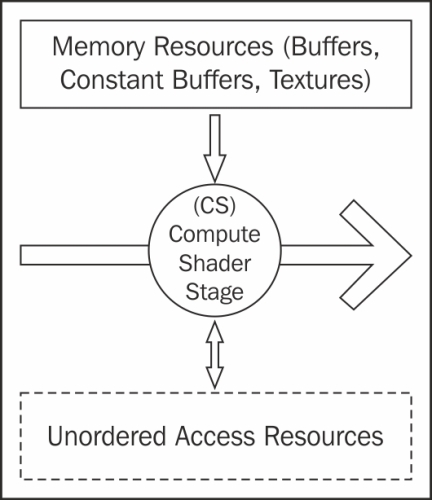
The dispatch pipeline is where compute shaders are executed. There is only one stage in this pipeline, the compute shader stage. The dispatch pipeline and graphics pipeline cannot run at the same time and there is an additional context change cost when switching between the two, therefore calls to the dispatch pipeline should be grouped together where possible.

Direct3D Dispatch/DirectCompute Pipeline

Compute Shader (CS) stage

The compute shader (also known as DirectCompute) is an optional programmable stage that executes a shader program upon multiple threads, optionally passing in a dispatch thread identifier (SV_DispatchThreadID) and up to three thread group identifier values as input (SV_GroupIndex, SV_GroupID, and SV_GroupThreadID). This shader supports a whole range of uses including post processing, physics simulation, AI, and GPGPU tasks.

Compute shader support is mandatory for hardware devices from feature level 11_0 onwards, and optionally available on hardware for feature levels 10_0 and 10_1.

The thread identifier is generally used as an index into a resource to perform an operation. The same shader program is run upon many thousands of threads at the same time, usually with each reading and/or writing to an element of a UAV resource.

Device context commands that control the compute shader stage are grouped in the ComputeShader property or begin with CS in the unmanaged API.

After the compute shader is prepared, it is executed by calling the Dispatch command on the device context, passing in the number of thread groups to use.