
To make a rectangle, use the REC command or use the Rectangle tool from the Draw panel in the Home tab. The rectangle command will help you make a four-sided rectangle or square. There are a few different ways of making a rectangle using the rectangle tool. We will first learn how to make a rectangle using coordinates and later, we will also see the method of making a rectangle using Dynamic Input. Let's begin by using coordinates to make our rectangle.
Making a rectangle
Making a rectangle using absolute coordinates
To make a rectangle using coordinates, you need to deactivate the Dynamic Input option from the status bar. To turn it off, click on its icon in the status bar or press the F12 function key:

Figure 2.38: Dynamic Input mode in the status bar
When Dynamic Input is on, a tooltip will show next to your cursor and when it is off, you won’t see a tooltip, as in the following screenshot:
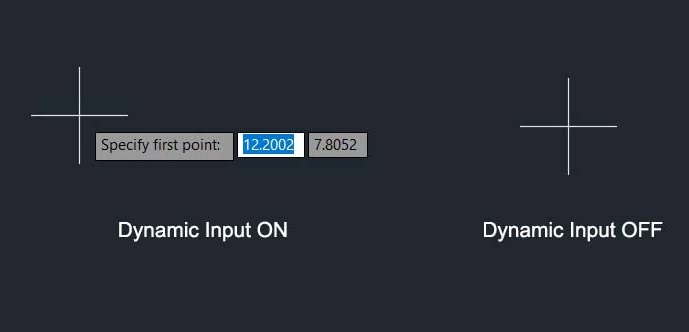
Figure 2.39: Cursor mode when Dynamic Input is on and off
Here, I will make a rectangle that starts from the origin and has a length of 8 units and a width of 3 units:
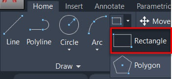
Figure 2.40: The Rectangle command in the Draw panel of the Home tab
The following is the workflow for making this 8 x 3 rectangle:
- Click on the Rectangle tool in the Draw panel or type the REC command and press Enter.
- The command line will prompt you to specify the first point. Type 0,0 and press Enter.
- Then, type 8,3 with the next prompt and press Enter again.
- The final rectangle will be made with a length of 8 units and a width of 3 units.
In this case, the first point was the lower-left point of the rectangle, shown as 1 in the following diagram, which is also the origin, and the second point was the upper-right vertex with coordinates 8,3, shown as 2 in the diagram:
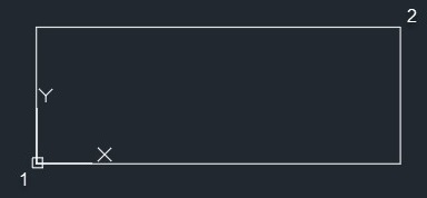
Figure 2.41: A rectangle with the lower-left corner on the origin and the upper-right corner on point 8,3
For point 2, we added 8,3, where 8 is the length as well as the X coordinate value and 3 is the height of the rectangle as well as the Y coordinate.
Making a rectangle using relative coordinates
In the previous example, the rectangle started from the origin; hence, the coordinates of point 2 also represented the length and width. However, if you don’t want the rectangle to start from the origin and you instead want it to start from any other point, then you need to use the relative coordinates, which are explained here:
- Start the Rectangle command from the Draw panel or use its REC command.
- Click on any point in the drawing area to specify the first point of the rectangle.
- Type @8,3 and press Enter to specify the next point of the rectangle.
- The rectangle will be made with a length of 8 units and a width of 3 units.
In this case, we have used the @ sign before the point 2 coordinates because the first point was chosen randomly from the drawing area and it was not on the origin. So, adding the @ sign makes point 1 the origin for this particular case and the values of point 2 will be measured with respect to the first point.
If you start the Rectangle command from any random point and add the second point as 8,3, then the second point of the rectangle will end up on the absolute 8,3 point, with respect to the absolute coordinate system, and the length and width of the rectangle, in this case, won't be 8 and 3, respectively.
Making a rectangle with Dynamic Input
Using Dynamic Input skips all these issues that we have with coordinates and lets you directly add the length and width of the rectangle, so you will have your rectangle with those dimensions. Before we make a rectangle using the Dynamic Input status bar option, we need to first activate it:
- Activate the Dynamic Input status bar option by clicking on its icon or using its function key, F12.
- Start the Rectangle command from the Draw panel of the Home tab or use its REC command.
- You will notice a tooltip next to your cursor with coordinate values in real time. Click on any point to specify the first point of the rectangle:
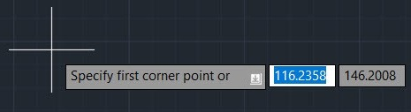
Figure 2.42: The first point option of the Rectangle command on the cursor tooltip when Dynamic Input is active
- Type the length of the rectangle along the X axis and press the Tab key. The length of the rectangle will be locked to a 10 units length and the Y axis width field will become active:
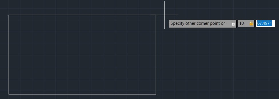
Figure 2.43: The length value locked on the tooltip in the rectangle command
- Type the width value along the Y axis of the rectangle and press Enter again. In this case, I am using a width of 5 units.
The rectangle will be made with a length of 10 units and a width of 5 units. In this case, we used a positive value of X and Y that is, 10 and 5, but you can use negative values as well to make the rectangle in different quadrants with respect to the first point. For example, the -10 and 5 units will make the rectangle in the second quadrant, -10 and -5 will make it in the third, and 10 and -5 will make the rectangle in the fourth quadrant. The following illustration will clarify this point further:
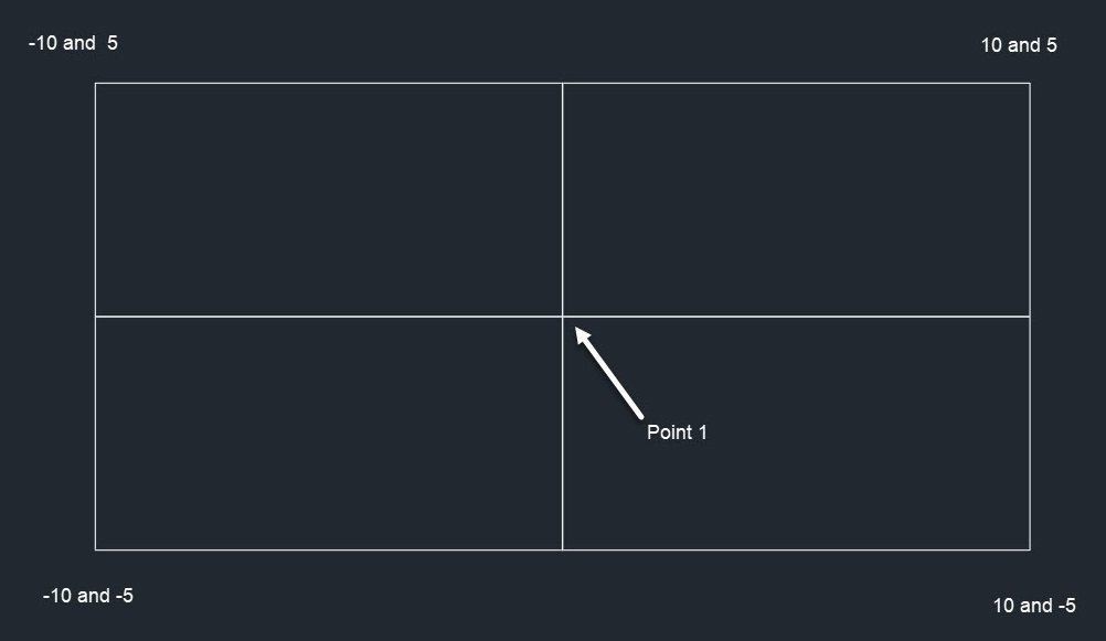
Figure 2.44: The four coordinate points of the rectangles with respect to the common starting point of the rectangle
The rectangle is a four-sided polygon but, in AutoCAD, you can make other polygons, such as a pentagon, hexagon, and heptagon as well. You can even make a polygon with tens or hundreds of sides. You can do all of this using the polygon command, which we will explore next.