
Creating a multi-body part design
In this recipe, you will create a small subassembly of parts to complete the design of a mountain bike shock absorber. You will learn how to create multiple bodies, in a model, and add features to the bodies. The completed assembly is shown in Figure 2.5, which includes the subcomponent that you will design using the multi-body design process. The rest of the components are supplied as separate solids.
Figure 2.5 shows the completed assembly of the shock absorber containing the part we will create:
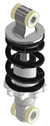
Figure 2.5: Full assembly of the shock absorber part we will create
Getting ready
Start to familiarize yourself with Figure 2.5 as it contains the part we will make (dimensions are not given yet but will be given to you in stages throughout this recipe).
The files that you need for this recipe can be found in the Chapter 2 folder of the Inventor 2023 Cookbook folder.
You can also open Shock_Absorber_Assy.iam as a reference, which can be found in the Chapter 2 folder too (although it is not needed directly for the recipe).
How to do it…
To begin the recipe, we will need to create the first component within the assembly:
- Start the creation of a new part file using the
Standard Metric (mm) .ipttemplate. To do this, select File | New | Metric. ChooseStandard (mm) .iptfor the template, then click Create to complete. - Select Start 2D Sketch and select the XY plane by expanding the Origin folder in the Model Browser.
- From the Sketch tab, in the Create panel, select Circle and create an
18 mmdiameter circle that is centered on the origin, as shown here in Figure 2.6:
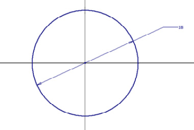
Figure 2.6: The start of the initial sketch
Next, create the rest of the sketch geometry, as shown in Figure 2.7. To do this, draw a construction line from the origin of the circle downward by 21 mm. Next, from the end point, create a horizontal 9 mm line from the construction line end point, then a 3 mm vertical line from the end point of the previous line. This is shown in Figure 2.7:
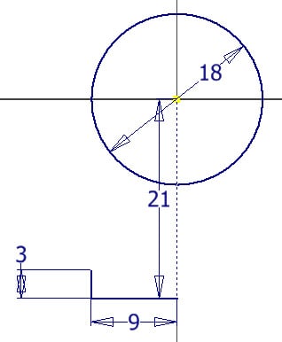
Figure 2.7: The next sketch lines to apply
Ensure the sketch is fully defined before progressing to step 4.
- Next, to create the arc, select the Three-Point Arc command. Start at the end point of the line that is
3 mmin length and snap to the edge of the circle. Set the radius of the arc to15 mm. To fully constrain this arc, you will then need to add a tangent constraint between the arc and the circle, as shown in Figure 2.8:
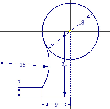
Figure 2.8: 15 mm three-point arc created with a tangency relationship applied between the arc and circle
- As this is a symmetrical shape, we can use the Sketch Mirror command to copy the existing sketch lines about the centerline. This saves time and is the most efficient way to create this sketch. With the Mirror command, mirror all geometry, except the circle, using the center construction line as the mirror line.
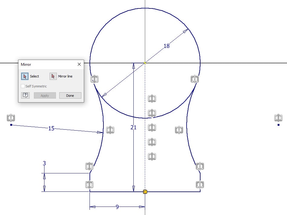
Figure 2.9: The sketch with the mirror applied
- Complete the sketch by selecting Finish Sketch. In the 3D Model tab, select Extrude and select the two closed profiles of the sketch. Enter a value of
14 mmfor Distance A. Then, ensure Direction is set to Symmetric, then select OK.
In this case, with 14 mm set as the overall extrude length, this extends the extrusion both ways by 7 mm in each direction.
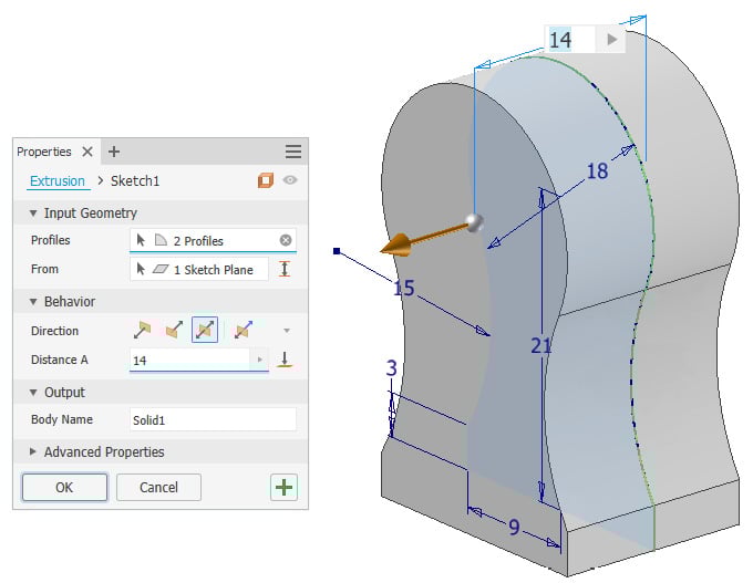
Figure 2.10: Extrusion of the profile applied at 14 mm from the center in both directions
- We will now create additional features on the model as part of the same solid. Select Start 2D Sketch and create a new sketch on the face shown with the following geometry. Select Project Geometry and proceed to select the face of the part, before creating the circles, as per Figure 2.11:
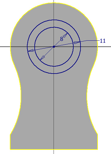
Figure 2.11: The sketch geometry required to create the next features of the part
- Use the Extrude tool on the outer circle to extrude it by
5 mm. - We will now cut the center of the circle. Select Extrude, then Cut, and change Distance A to Through All. Select OK.
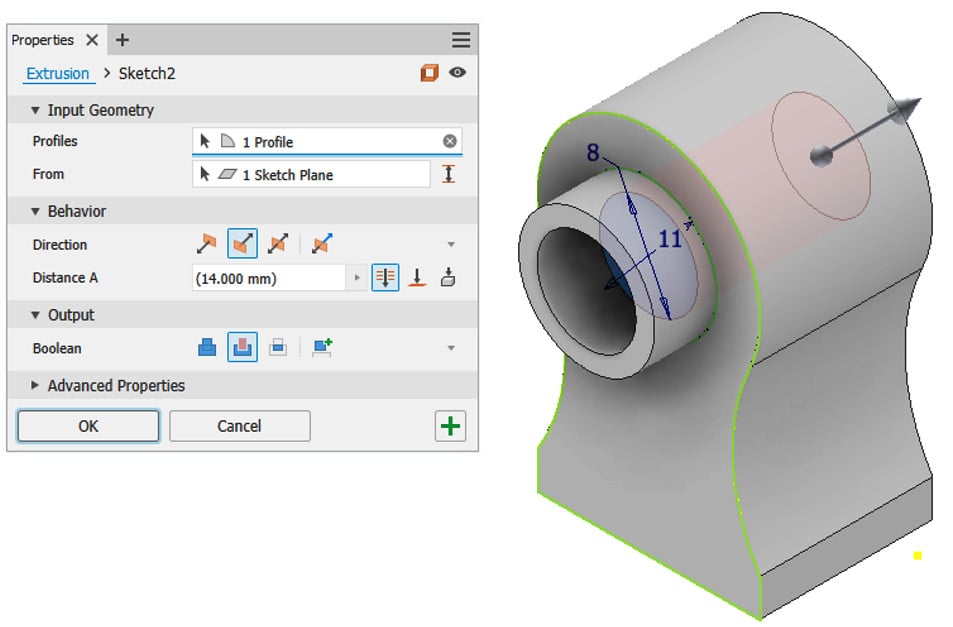
Figure 2.12: The two extrusions created in the same operation
Using the XY plane, in the 3D Model tab, select Mirror and mirror the protruding extrusion from the Model Browser. This replicates the extrusion we created previously, but on the other side of the part.
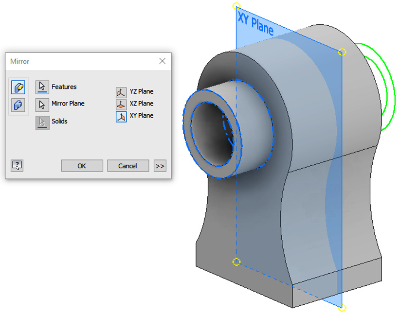
Figure 2.13: Mirror operation in action showing the plane and copied feature geometry
- Select Start 2D Sketch and select the base of the model as the sketch plane. Select Circle and create a
10 mmdiameter circle central to the base of the model. Once complete, select Finish Sketch and then extrude the circle by50 mm, in the direction away from the model. This is shown in Figure 2.14:
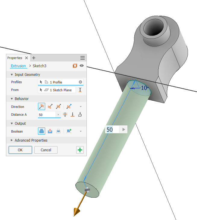
Figure 2.14: 10 mm circle extruded by 50 mm from the base of the part
The first solid body is now complete with additional features added. In the Model Browser, you will see the Solid Bodies folder now shows (1). The additional solids will now be created within the part file.
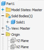
Figure 2.15: Solid Bodies folder of the Model Browser expanded, showing one solid body in the part file
- Next, select Start 2D Sketch and create a sketch of the face shown in Figure 2.16. The circle must be
18 mmin diameter.
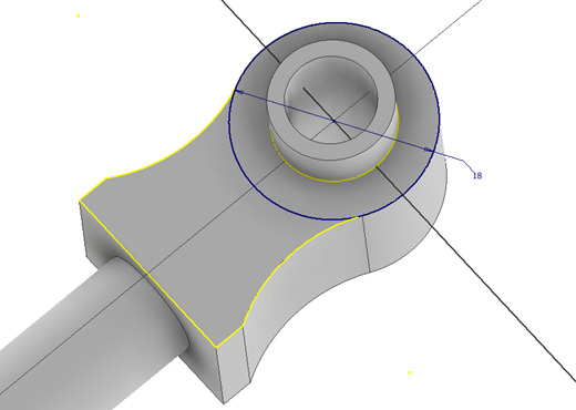
Figure 2.16: Sketch of the circle that must be created, 18 mm in diameter
- This sketch now becomes the basis for the second solid we will create in this part file. Select Extrude and then select the sketch profile created previously in step 11. Set Extrusion Type as To. Select the face of the internal cylinder of Solid1 as the face to extrude toward.
Crucially, at this stage, open the Output area of the Extrude menu and set Boolean as New Solid. This will create the feature as a separate and independent solid from Solid1. Select OK to complete this.
A second solid has now been created.
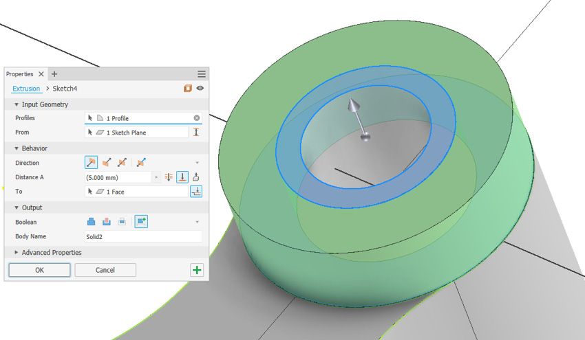
Figure 2.17: Creation of the new solid using the Extrusion command
- As a new solid has now been created, we will begin to modify it. Select Fillet and apply a
.5 mmfillet to the edge of Solid2, as shown here in Figure 2.18. Select OK to close the command.
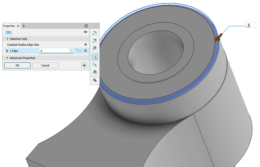
Figure 2.18: .5mm fillet added to the new Solid2 edge
- A final modification we will make to Solid2, independent of Solid1, is a property change. In the Model Browser, expand the Solid Bodies folder, right-click on Solid2, and select Properties.
- In the Body Appearance drop-down list, select Smooth Ivory, followed by OK. We have now independently applied an appearance change to Solid2.
A second instance of Solid2 is required on the other side of Solid1; rather than creating or modeling this again, we can mirror Solid2 along the XY plane to create a second identical instance of Solid2.
- To do this, navigate to the 3D Model panel and find the Pattern commands, and select Mirror. In the Mirror command, rather than using the default Mirror feature, select Mirror Solid. Then, select Solid2 from the Graphics Window. For Plane, use the XY plane. Make sure to also select New Solid in the command as the default will be Join. Select OK to complete. This menu and settings are shown in the top left of the menu in Figure 2.19:
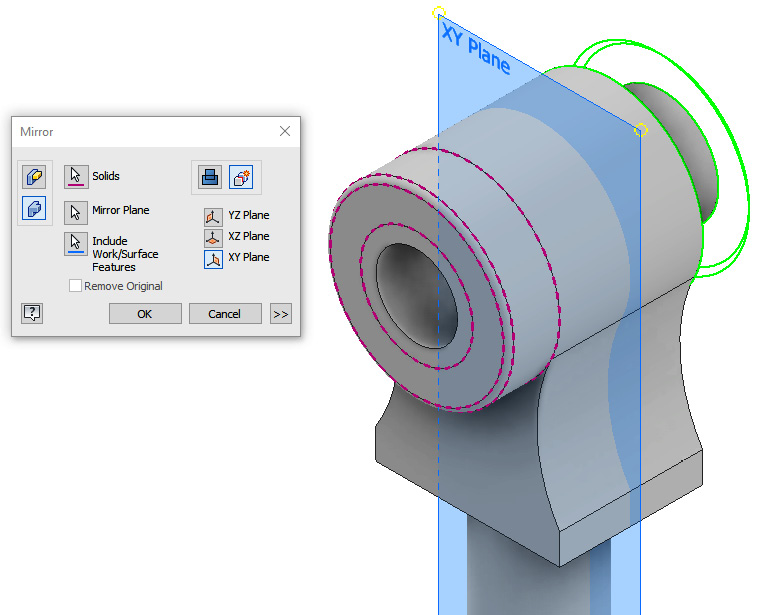
Figure 2.19: Mirror command dialog box showing the settings that need to be applied to mirror Solid2
- Solid3 has been created. The appearance has not transferred from the mirror as this is controlled by the solid properties. In the properties of Solid3, change the appearance of Solid3 to Smooth Ivory (as you did for Solid2 previously).
- To show how all three solids can be edited together, we will now create a small
1 mmhole that goes through all three solids created. Create a new sketch on the face of Solid2, as shown in Figure 2.20. Add a sketch point where the arrow is shown and then exit the sketch.
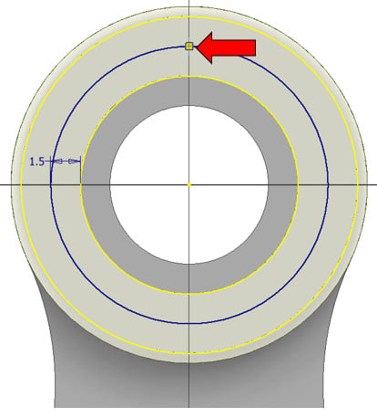
Figure 2.20: Sketch to be created on Solid2 with an arrow indicating the location of the sketch point
- Select the Hole command and pick the sketch point previously placed as the location. Set the Hole type as Simple, the Seat type as None, and the Termination type as Through All with a
1 mmdiameter. In the Solids area, select all three solids to enable the hole to pass through all three independent solids created. This shows how you can perform feature edits in multi-body design, on multiple solids at once if required. Select OK to complete the hole.
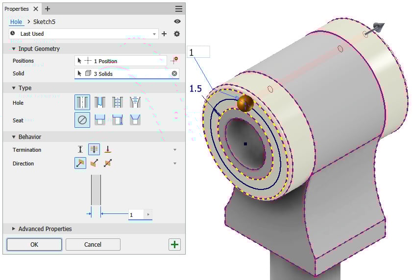
Figure 2.21: Hole command with settings applied in step 19, showing hole going through all three independent solids
- Now, you will extract the solid bodies created to create three independent part files; this is the final stage of multi-body part design. To start, select the Manage tab, then Layout panel. Select Make Components. Inventor will prompt you to save the file. Save the file as
Part1.iptin theShock Absorberfolder, within theChapter2folder. - Select the three solid bodies from the Model Browser to be included in the selection and uncheck Insert components in target assembly (this is not required in this case, but would enable you to also build an assembly of solid body parts at the same time). Then, select Next.
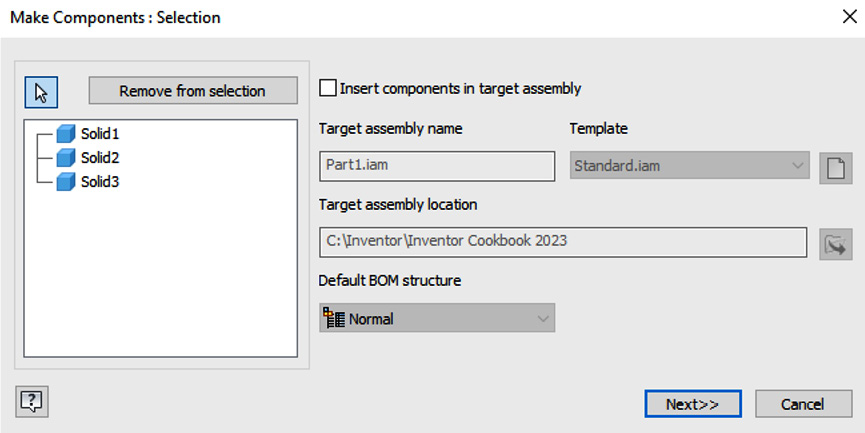
Figure 2.22: Make Components dialog box with the options required
- You can now rename components and choose the template file you want them to use. You can also include any previous parameters and edit the BOM structure.
Select Solid 1 and change the name to SA_MALE_1.ipt. Repeat this for the two other solids, as shown in Figure 2.23, with sequential numbers, in the Component Name column.
Then, select the Page button above the Template column. Navigate to the Metric tab and select the Standard (mm) .ipt template to use. Then, click OK.
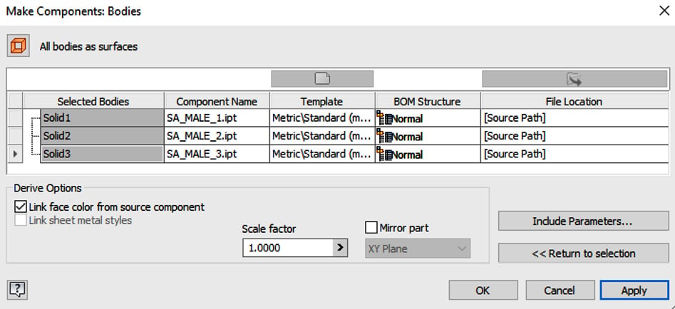
Figure 2.23: Make Components: Bodies dialog box with component names changed and templates redefined
- Inventor will now create the solids as separate
.iptfiles. To review the results, click OPEN and navigate back to theInventor 2023 Cookbookfolder, where the solid parts will be located. This is shown in Figure 2.24:
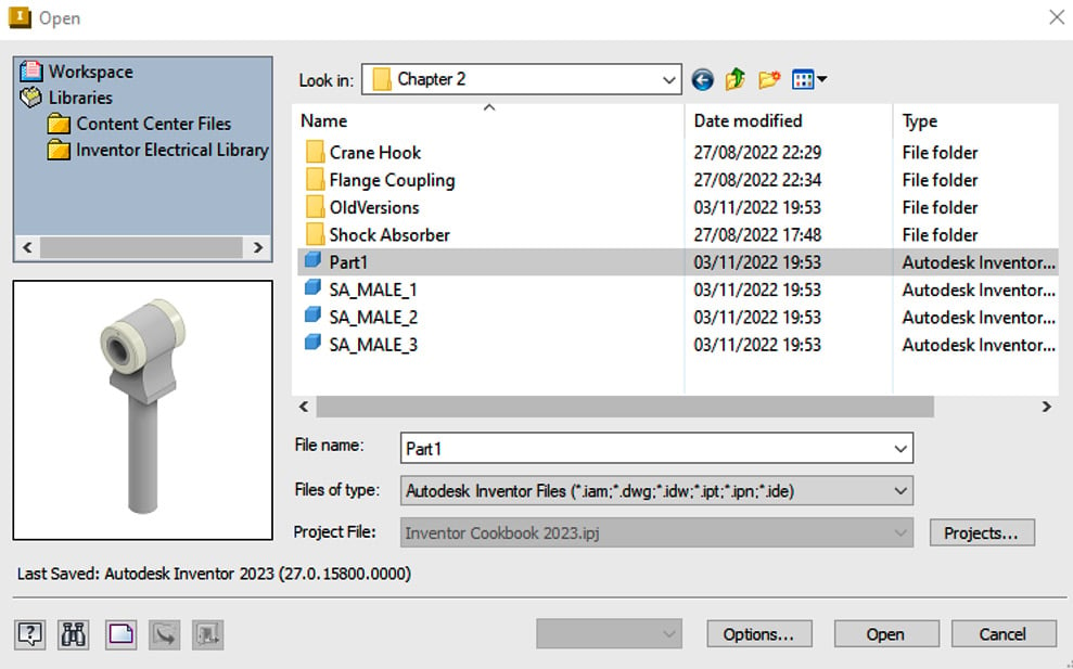
Figure 2.24: Newly created separate .ipt part files from the solids initially created
In this recipe, you have successfully created three independent solids as part of a multi-body design workflow to create a subassembly of parts for a shock absorber. You have then exported each solid as a separate part file. The parent multi-body part file is associative with the exported independent parts, which means that if we change the parent part, the child (exported) parts also change.