
Applying and using adaptive modeling
Adaptive modeling involves creating parts within the context of an assembly. An initial part is created and then placed and grounded within an assembly file. Other parts are created in place from the original part in the assembly file.
In this recipe, you will take an imported flange coupling assembly and create a mating plate and gasket that are adaptively linked. This means that as changes are made in one component, they will automatically be reflected in the linked components, without manual design changes. This is known as an adaptive link.
Getting ready
In the Chapter 2 folder, select the Flange Coupling folder. Then, open Flange Coupling.iam.
How to do it…
To begin, we will open the existing assembly. Then, we will create new components within the context of it:
- With the
Flange Coupling.iamassembly open, navigate to the top left of the screen, to the Assemble tab, and select Create. The menu shown in Figure 2.68 will appear. - Enter
Gasketfor New Component Name and set Template to Metric\ Standard (mm).ipt. Ensure New File Location is set toC:\Inventor\Inventor Cookbook 2023\Chapter2\Flange Coupling\.
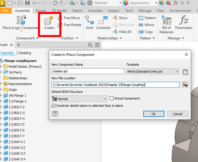
Figure 2.68: Create button in the ribbon, with the Create In-Place Component window active
- Select OK. Inventor then prompts you to pick a face or plane to build the new component. Select the face highlighted in Figure 2.69:
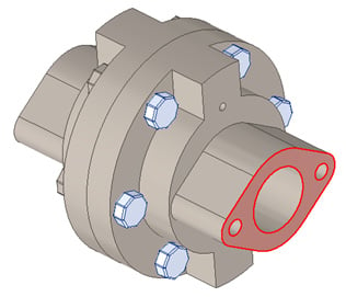
Figure 2.69: Face selected
- The model will now turn transparent. Select Start 2D Sketch and pick the same face previously selected, in step 3.
- In the new sketch, select the Project Geometry command, and then select the face shown in Figure 2.70 to project all the edges shown:
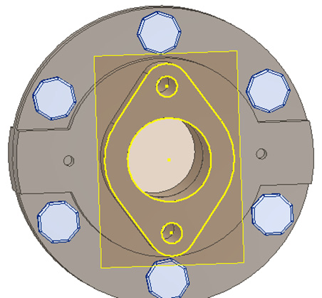
Figure 2.70: Projected geometry shown
- Select the Extrude command and select the profile previously created in step 5. Extrude the gasket by
1.5 mmand select OK.
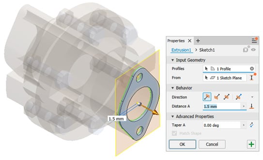
Figure 2.71: Extrusion of previously created projected geometry
- Select Return to complete the gasket. Notice that in the Model Browser, next to the recently created gasket, blue and red arrows are placed next to some features. This indicates that adaptivity has been created through the projection of geometry (if edits are made to the parent part, then these will be reflected in the child parts). Figure 2.72 shows the adaptive symbols in the Model Browser:
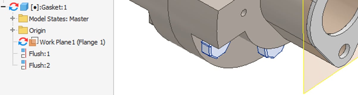
Figure 2.72: Adaptive symbols in the browser shown after the creation of the gasket
- In the top level of the assembly, create a new in-place component using Create as before, but this time select the top face of the recently created gasket to build the part on. Call the new component
Mating Plateand set Template tostandard (mm) .ipt. - Select Start 2D Sketch on the top face of the gasket and select Project Geometry, as shown in Figure 2.73:
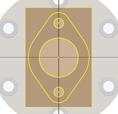
Figure 2.73: Projected sketch on top of the gasket for the creation of the mating plate
- Select Finish Sketch, and then select Extrude. Extrude the profiles shown in Figure 2.74 by
3.5 mm. Select OK to complete the operation.

Figure 2.74: Extrusion of the mating plate
- All additional adaptive parts have now been created. To observe the adaptivity, we will make changes to the original flange coupling components and observe how the newly created parts adapt:
- Right-click on Flange 1 from the Model Browser and select Edit.
- Expand the Extrusion 2 node and right-click on Sketch2, then select Edit Sketch.
- Change the dimension of the small hole to
2 mm; simply double-click Dimension and type the new value. The sketch holes update on completion.
- Select Exit Sketch, then select Return to return to the top-level assembly.
The Mating Plate and Gasket holes have now automatically updated to show the holes as 2 mm. No manual design work was required to complete this.
- In the Model Browser, click Flange 1 | Extrusion 2, right-click Sketch2, then edit the value back from
2 mmto5 mm. Exit and return to the top-level assembly and the parts will update, demonstrating adaptivity again.
This recipe is complete. You have created adaptive parts from an existing part file in the context of an assembly using the adaptive part modeling methodology.