Book Image

Practical Autodesk AutoCAD 2023 and AutoCAD LT 2023 - Second Edition

By : Jaiprakash Pandey, Yasser Shoukry
Book Image

Practical Autodesk AutoCAD 2023 and AutoCAD LT 2023 - Second Edition

By: Jaiprakash Pandey, Yasser Shoukry

Overview of this book

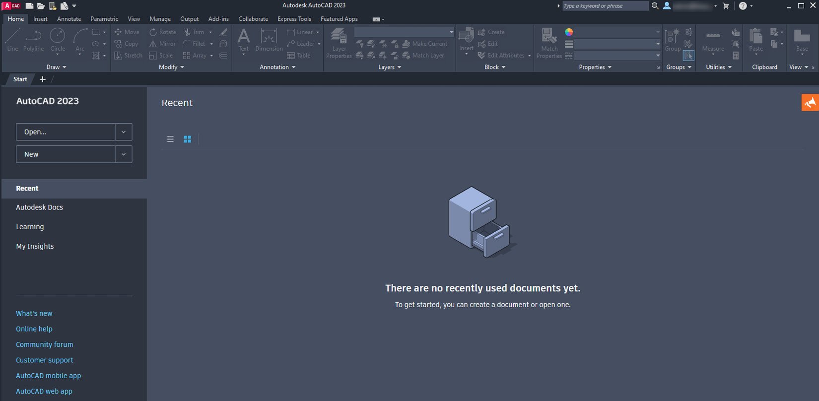
AutoCAD is one of the most versatile software applications for architectural and engineering designs and the most popular computer-aided design (CAD) platform for 2D drafting and 3D modeling. This hands-on 2nd edition guide will take you through everything you need to know to make the most out of this powerful tool, from a simple tour of the user interface to using advanced tools. Starting with basic drawing shapes and functions, you'll get to grips with the fundamentals of CAD designs. You’ll then learn about effective drawing management using layers, dynamic blocks, and groups, and discover how to add annotations and plots like a professional. As you progress, the book will show you how to convert your 2D drawings into 3D models and shapes. You’ll also discover advanced features, such as isometric drawings, drawing utilities for managing and recovering complex files, quantity surveying, and multidisciplinary drawing files using xRefs. Finally, you’ll focus on rendering and visualizing your designs in AutoCAD. By the end of this book, you’ll have developed a solid understanding of CAD principles and be able to work with AutoCAD software confidently to build impressive 2D and 3D creations.
Table of Contents (21 chapters)
1
Part 1: Introduction and 2D Drafting
6
Part 2: Customization, Collaboration, and Using Reusable Content
12
Part 3: 3D Modeling

Understanding the user interface

AutoCAD 2023, just like its predecessors, has a ribbon view with panels and tabs. You can launch the AutoCAD software using its icon on the desktop or from the AutoCAD 2023 – English folder in the Start menu. When the software loads up, you will see an interface like this:

Figure 1.1: The start screen of AutoCAD

Figure 1.1: The start screen of AutoCAD

This screen is called the Start screen and it is primarily divided into two parts: the left-hand column, where you will find frequently used tools to open a new file or template, and the middle chunk of the screen, where a list of all your old drawings will show up. You can open any older file simply by clicking its thumbnail.

To open a new blank drawing, click the New button right underneath the Autodesk AutoCAD 2023 placeholder. This will open a new tab with the last used template.

To see the last used template, click the arrow next to the New button and a list will open up; at the top of this list, you will see the last used template.

Usually, the default template is acad.dwt or acadiso.dwt, but your template could be different. You can also select Browse Templates from the New button list to explore all the AutoCAD readymade templates, as shown in the following screenshot:

Figure 1.2: The New button menu in the start tab

Figure 1.2: The New button menu in the start tab

These templates contain settings such as units, limits, and precision. At this point, selecting any of these templates won’t make a difference, as we will learn about making templates and using them in drawings later in this book.

So, when the blank drawing loads up, your interface will look similar to the Start screen, but this time, with an active ribbon and blank drawing area. Let’s talk about all the components in this workspace:

Figure 1.3: The AutoCAD 2023 user interface

Figure 1.3: The AutoCAD 2023 user interface

The user interface parts are labeled in Figure 1.3 and here is a short description of each of the parts mentioned in this screenshot.

The application button

Clicking on this big A icon will open a menu with options to open an existing drawing; open a new template; save, print, or export drawings; and other common options.

The quick access toolbar

This toolbar contains most of the frequently used tools from the application button. To add or remove an option from the quick access toolbar, simply click on the arrow pointing downward at the end of the toolbar and check or uncheck the option you want to keep or hide:

Figure 1.4: The quick access toolbar

Figure 1.4: The quick access toolbar

The quick access toolbar contains tools such as open, save, plot, layer, workspace, sheet set manager, properties, and the menu bar. Some of these tools are also available in the application menu of AutoCAD.

The info bar

In the input field of the info bar, which reads Type a keyword or phrase, you can type the name of any command or tool to get more information about it. Simply type the name of the command and hit the Enter key to get the help file related to the command. You need to be connected to the internet in order to use this feature. This bar also contains other features, such as your sign-in account, access to the Autodesk app store, and more Help options.

The ribbon area

The ribbon area contains all the tools and commands properly arranged into different tabs and panels. Home, Insert, Annotate, Parametric, and so on are the tabs in which different panels are placed in a meaningful order. For example, the Home tab contains the Draw and Modify panels, which, in turn, contain most of the frequently used commands:

Figure 1.5: Tabs and panels in the AutoCAD ribbon area

Figure 1.5: Tabs and panels in the AutoCAD ribbon area

Similarly, other less frequently used panels and their subsequent commands are in other tabs, such as the Parametric or Express Tools tabs, which are other tabs found in the ribbon area.

The panels and tabs are not permanent and you can hide or reveal them by simply right-clicking on any panel. To show any tab, just right-click on any panel and go to the Show Tabs option. Then, check the tab that you want to show; similarly, to hide any tab, repeat the same process and uncheck the tab from the right-hand side context menu:

Figure 1.6: The Show Tabs and Show Panels options

Figure 1.6: The Show Tabs and Show Panels options

To hide or show any panel of a tab, just go to the tab and right-click on any of its panels. Then, right-click and go to the Show Panels option to check or uncheck the panels that you want to show or hide.

The file tabs

The file tabs show the drawing files that are open in the current session of AutoCAD. You can open as many file tabs as you want. To open a new blank drawing, click the + icon next to the last file tab:

Figure 1.7: The file tab options

Figure 1.7: The file tab options

The padlock icon in a file tab indicates that the file is read-only and you can only view that kind of file and not modify it. Hovering the cursor over any open tab also shows the thumbnail preview of the drawing. To open the drawing of the selected tab, simply click on the thumbnail that shows up on the cursor.

The ViewCube and navigation bar

The ViewCube is an AutoCAD-only tool and is not available in AutoCAD LT, whereas the navigation bar is available in both AutoCAD and LT (although in LT, it is somewhat limited in features). If you don’t see the ViewCube, simply go to the top left of the display area, click on the sign, then select ViewCube and Navigation Bar:

Figure 1.8: The ViewCube and Navigation Bar options

Figure 1.8: The ViewCube and Navigation Bar options

This sign won’t show up on AutoCAD LT, but you can use the NAVBAR command to turn it on or off.

The selection cursor

This is the cursor that shows up on the AutoCAD screen and it is basically two perpendicular lines with a small cube at the center of the intersection of the lines. This is the default state of the cursor and depending on the selection, your cursor might look different and sometimes additional icons will also show next to the cursor. These are the three most basic cursor modes; we will discuss the other cursor modes in this book as and when needed:

Figure 1.9: The different cursor modes

Figure 1.9: The different cursor modes

The Default Cursor type appears when none of the commands are active, so essentially, this first cursor type is visible in the default state of AutoCAD. When you activate a command where you need to select a precise point, the second cursor – Point Selection – appears, which is just two mutually perpendicular lines intersecting at the midpoint. The Object Selection cursor will be visible when a command where object selection is required is active.

No matter which of the cursors shown in the preceding figure is active, if you want to return to the default state of the cursor, then simply press the Esc key on your keyboard. You can press the Esc key multiple times and it won’t affect the default state of your cursor.

The command line or palette

Just at the bottom of the drawing area, you will see the command line or command palette. In this book, I will refer to it as the command line. All your typed commands will show up in this command line. You don’t need to click on the command line to start typing any AutoCAD command; just start typing without selecting anything and the input will be added to the command line directly. In its default state, the command line will show the Type a command message and when you select any command, it will show the name of the command and, next, a set of instructions in the command line, as in the following screenshot:

Figure 1.10: The different states of the command line

Figure 1.10: The different states of the command line

If for some reason you don’t see the command line, then press the Ctrl + 9 keys to turn it on; you can press Ctrl + 9 again to hide the command line. This command line is like a floating palette and you can even resize it or move it around in the drawing area. You can see a list of previously entered commands in the command line by pressing the F2 function key.

The user coordinate system

The user coordinate system (UCS) shows the X, Y, and Z directions of the Cartesian coordinate system in the drawing area. Usually, the UCS will be visible in the bottom left-hand corner of the drawing area:

Figure 1.11: The UCS with an X and Y axis

Figure 1.11: The UCS with an X and Y axis

In the default state of the 2D workspace, the UCS will only show the X- and Y-axis; the Z-axis, which points outward from the AutoCAD screen, will not be visible. The point of intersection of the X and Y coordinates in this UCS is the origin, or 0,0, point. We will discuss using the Cartesian coordinate system in greater detail later in this chapter.

The layout tabs

The layout tabs are like the sheets of your drawing on which you can arrange different views and finally, plot multiple sheets. For example, if you have a house plan in a model space where the floor plan, elevations, section, and detail drawings are all made in the model space, then you can use the layout tabs to place them separately on different sheets, such as a layout for plan view, another for all elevations, and another for all detailed drawings. By default, the Model tab will be active and for most of this book, we will work inside the Model tab. We will learn about layouts in Chapter 14, Paper Space Layouts and Printing.

The status bar toggles

The options in the status bar help make drawings precise. The tools in the status bar, such as Object Snap, help you to select precise points, such as the midpoint and endpoints of any geometry, and tools such as polar mode and ortho mode help you to make lines that are inclined at any angle or horizontal and vertical lines. The toggles on the status bar can be turned on by clicking on them once, and similarly, clicking on them again turns them off. Most of the status bar tools have function key shortcuts as well, and you can find the function key shortcut of any status bar option by hovering your cursor over it:

Figure 1.12: The status bar toggles with the customization option

Figure 1.12: The status bar toggles with the customization option

Not all of the status bar options are visible in the status bar and to make the options visible or hide them, use the customization option, which is the three lines at the end of the status bar. Just click on the three lines, shown at the bottom right of Figure 1.12, check the options you want to show on the status bar, and uncheck the ones you want to hide. We will learn more about the status bar options later in this book.

So, now that you are familiar with the user interface and the way the ribbon area works, let’s move on to the navigation tools. In the next section, we will talk about the navigation tools and how these tools can be accessed using the mouse or from the AutoCAD interface.