
What are planes?
Planes are flat surfaces that you can use to create sketches, use as references to build other geometry, or use as cutting tools. When you first start Fusion 360, you will notice that you have a large grid with red and green axes and a central dot. The dot is your origin (0,0) location, with the red line being your x axis and the green line being your y axis:
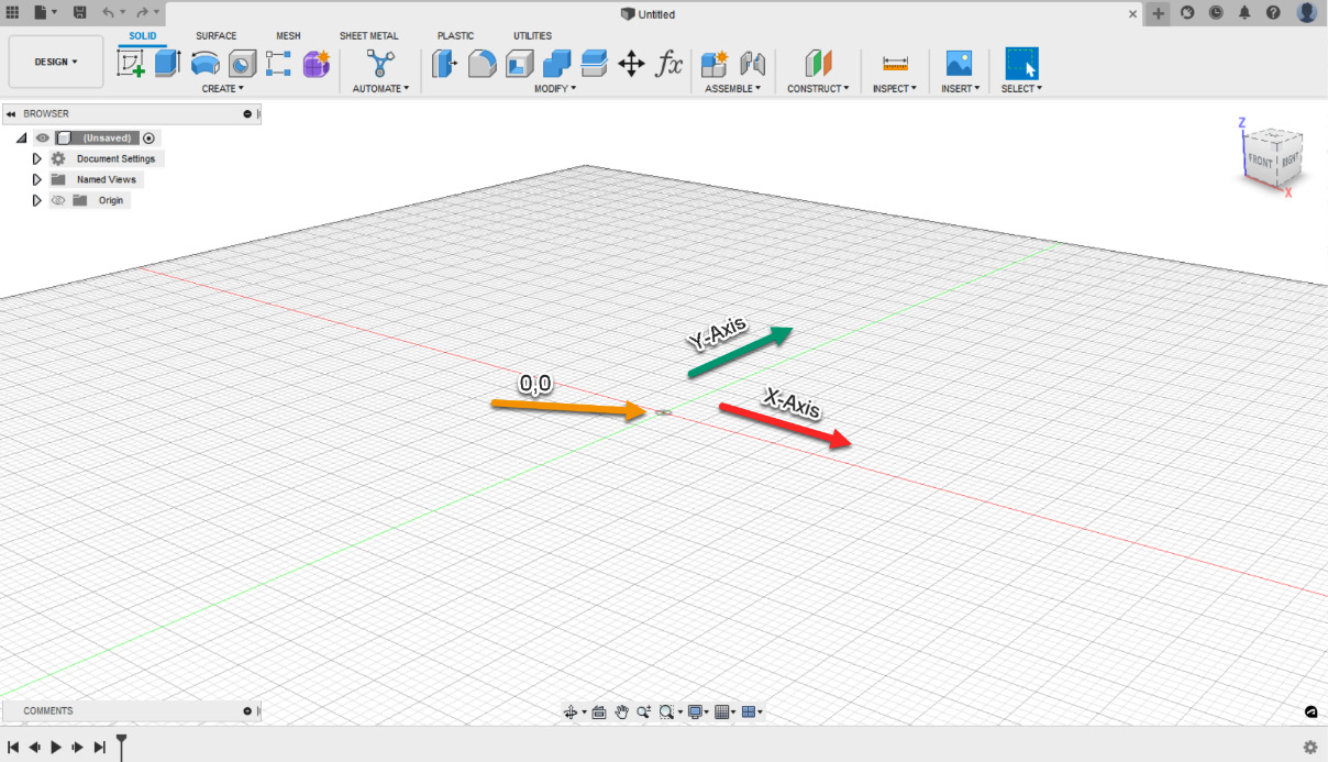
Figure 2.1 – Origin location on a grid
Choosing any tool in the toolbar, such as the Box tool under the SOLID tab within the CREATE panel, you will see three planes appear on your screen with a Select a plane or planar face option:
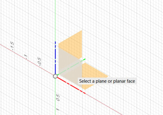
Figure 2.2 – Planes once a command has been chosen
Think of these planes as your drawing paper, and you can choose which side of an object you want to draw on. These planes represent the top, side, and front views of your object.
Once you choose a plane by left-clicking on it, you can then draw the size of...