

Creating a reference model using primitives
Using primitives is a great way to get the basic shape of your reference model without having to use too many details. It’s a quick and easy way to get your project moving forward. It is limited, though, by its basic function, so just be aware that this is not the preferred way to build since it is not a parametric model.
Here is how we can create our reference model of the handlepost and handlebars using primitives:
- Within the SOLID tab, click on the CREATE drop-down arrow, and select Cylinder.
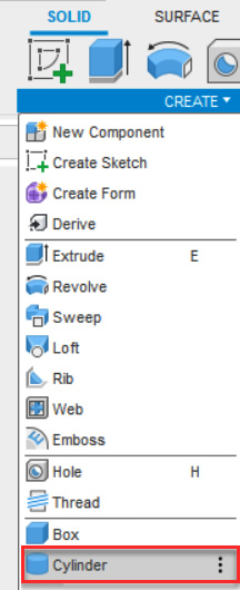
Figure 7.7 – The Cylinder tool location
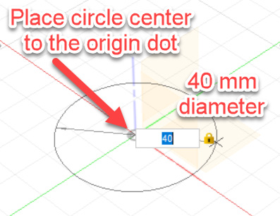
Figure 7.8 – Placing a cylinder on the XY plane
- Type in a diameter of
40 mmand hit Enter. - The CYLINDER flyout will appear. Type in
270for Height and hit Enter.
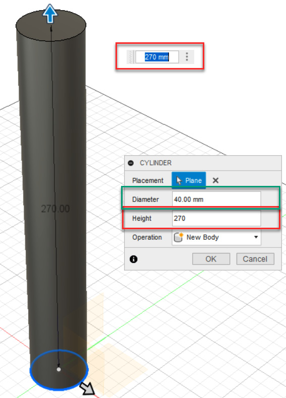
Figure...