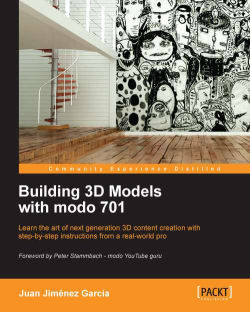

If you have some previous experience with 3D software, you will notice a typical 3D interface and a big workspace showing a single perspective view surrounded by a bunch of buttons. If you are new to all this, then it's time to explain what this is all about.
First of all, take a look at what will be the main workspace you will be using. A single perspective visor occupies the main part of the screen. That's a perspective view of your model. If you look at the top of it, you will see the information you need to identify it.
This information is divided in to two parts: information about the visor and how it displays the view (in the left-hand side corner), and general controls for zooming, panning, and rotating the basic stuff. You can see three big buttons in the left corner of each visor (giving information about the view represented, the kind of display it is showing, and a third button called RAY GL, which is off by default). We will see the RAY GL mode later on, since it's related to the rendering phase, but it's important to know about the other two.
For the first button, you will notice there is a difference in each viewport. I'm sure you have guessed the meaning of it. It's telling you what view you are seeing in each one. That's Top for the top view, Perspective for the perspective view, and so on. We will see their uses in the customizing part.
These viewports (and the layout of viewports) are customizable, as we will see later. But for now, just know that you have all the information for the visual control of your scene.
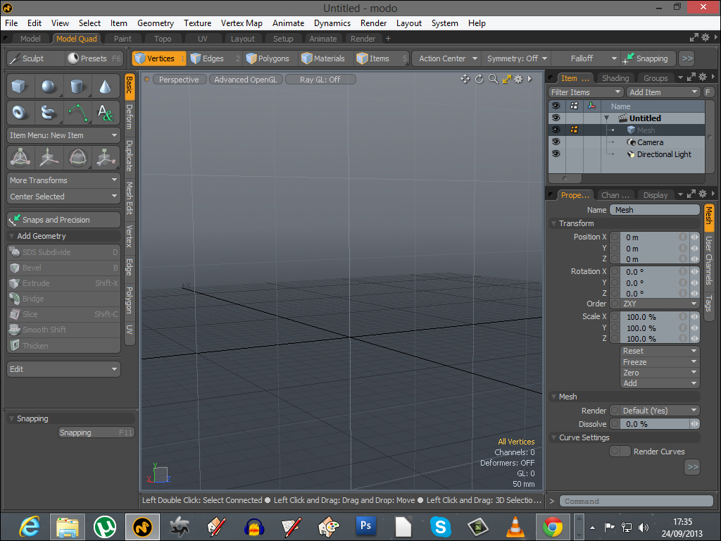
Let's focus on controlling the viewports. Viewports are not fixed in any way. You can manipulate them, change their size, position, maximize/minimize them, change their properties, and so on. That's what the control area—on the top-right of each visor—is for. Since this section will talk about controlling the viewport, we will cover the use of the top-right controls.
If you look at the previous screenshot, there are a number of icons, some of them very clear about their function and others not. Let me explain what each of them do:

The panning tool
The first icon is for panning. You can click-and-drag this icon to pan over the image.

The rotating tool
The second is for rotating. Click-and-drag over this icon to rotate the image. Of course, this button only works in a perspective or camera visor, since the rest of the views are unable to rotate, due to its very nature.

The zooming tool
The third is the zooming control. Again, click-and-drag left or right to zoom in and out.

The maximizing tool
The fourth is the maximize button. Nothing fancy here. Just click on it and the visor will expand to occupy the whole workspace. Click on it again to return to the previous viewport setup.

The options button
The fifth (the one shaped as a gear) is the options button. If you click on it, a menu will show up with all the options you need to customize that particular visor. It's divided into tabs, each one related to particular aspects of the visor. You can change things such as visibility of the wireframe, colors, mesh displays, and backgrounds. But for now, and being an introductory explanation of the interface, my advice is that you don't mess too much with this menu. The standard values should be good for you. Anyway, feel free (and it's a good thing) to experiment with some of these options to see the effect on the display of the viewport.
Now that we know how to control the views, we can move on to the next step, which will be customizing the viewports as per our own likings.
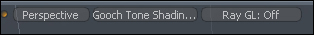
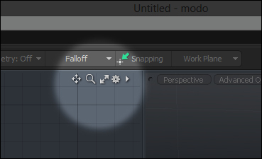
For this, we will look at the top-left corner of any viewport. You will see a set of three buttons. As I said earlier, we will ignore the third button (RAY GL) and will instead focus on the other two.
If you look at the preceding screenshot, you will see the first button says Perspective. As you guessed, this button shows us information about the type of view that visor is showing. Notice that there is a different view on each of the viewports. Of course, you can change the view to the one you like. Click on that first button to see a menu of views you can switch to. There are options to change the view to the camera view or to the light view.
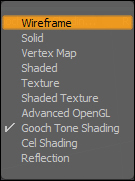
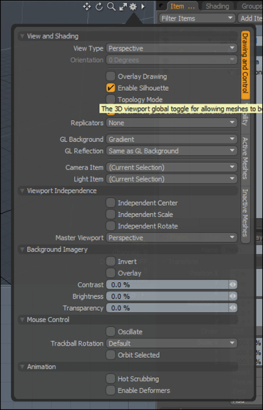
The second button is a bit more complex. It tells us the style of view this viewport is giving. In the preceding screenshot, you will see the list of styles you can choose. There are many, and as each have their own strong points, you will choose the one that is more useful for you depending on what you are doing.
Personally, the most important styles for me are wireframe, advanced OpenGL, and reflection. For me, these three styles are the basic styles you will be using most of the time. Let me show the difference between them briefly with the following screenshot:
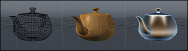
In the preceding screenshot, you can see the three styles side-by-side; first is the wireframe. This style lets us see what's not visible normally (the back of the model or hidden parts). It also shows us a clear understanding of the topology of the mesh.
The second style is called Advanced Open GL. It shows models with textures applied. It's useful to see our model with correctly-scaled textures applied. It also shows basic reflections in real time. This is very useful if we want to see a fast preview of our texturing, especially if we disable the wireframe in the options menu of the viewport, which is a good practice for new users to get used to from the beginning.
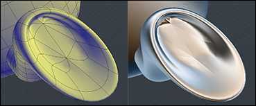
The third image is the reflection style. What this style shows is how the reflections will be calculated in that mesh (if we set its material to be reflective). This is very useful to see (even if the material is not reflective) how the mesh "flows", that is, if the modeling is well organized. So, if you rotate the visor in the reflection mode, you will see in real time how the reflections flow all across the model. If there is any bad modeling, the reflections will tell you. Look at the following screenshot to see the ugly reflections from a bad modeling:
As a last tip, you can also redistribute the viewports in the workspace. If you look at the interface, you will see that the visors are framed. And you can use the frames to resize the visors. That's simple! Just drag the vertical frame to the left or the right of the screen and you will see how one of the sides becomes bigger while the other becomes smaller. Drag the horizontal frame and the same will occur, but with the top and bottom part of the screen. You can also drag all the frames at once by dragging the point where the two frames meet (the center of the screen) and moving it freely while all the visors are resized according to where you drag their center.