
Now that we get the idea that modo's interface is divided into tabs, we're going to take a more in-depth look at what's under each one. Starting with the Model Quad tab, I want you to check the top-left panel, named the Tools panel. It contains the modeling tools you will need. Using these tools, we will be able to generate geometry, modify it, and make all sorts of operations in order to get our modeling done. Let's look at this panel in detail:
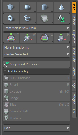
The Basic tab contains the basic operations for modeling. From here, you can generate primitives, manipulate your model (move, rotate, and scale), and perform other procedures that we will see later in this chapter.
So, what is a primitive? A primitive is a basic starting point from which you can build more complex models. These kind of objects are extremely basic (cubes, spheres, and the like). You can see what type of primitive you can generate just by taking a look at the buttons on the panel. You click on the Cube button, and you draw a cube; simple. There are two ways to generate a primitive:
By using the corresponding tool: Let's say you want to create a cube. The task is simple: just click on the Cube button and start drawing the cube inside any of the visors. First draw the base and then give it some height using the controllers.
Generating a unit primitive: If you press Ctrl and click on any of the primitives buttons, you will create a unit primitive. It's a simple shortcut to make primitive generation more simple and quick. By using this method, a standard primitive will be automatically generated without the need to draw anything.
Which method you choose for primitive creation will depend on your own preferences and the task at hand. It can often be more practical to generate a unit primitive and then modify it instead of using the tools to create a primitive of a specified size.
A mesh is formed by vertices, edges, and polygons. Their corresponding tabs will give you the tools to deal with each element. These three tabs are essential to work in the different selection modes (we will discuss this later). Let's take a look at what's basic about each one.
Under this tab, you will find many tools and operations related to vertexes:
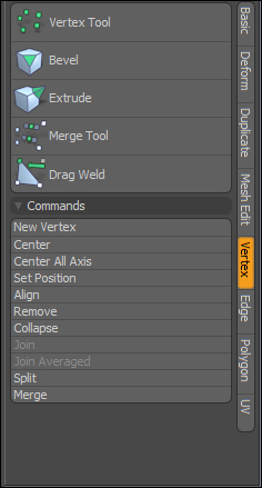
Let me show you the main and more practical options you will find here:
Center/Center All Axis: An axis is the imaginary line used as a reference for any of the dimensions in a 3D universe. Typically, axes are named x, y, and z (for width, height, and depth). I use this option very often. What it does is it takes all the selected vertices and places them in the center of every axis, which is the same as saying the center of the scene. This is very useful when I want to center a whole model. Just switch to vertex mode, click on Center All Axis, and the whole scene will be correctly placed in the exact center. If you use Center instead, a pop-up dialog will ask you for the axis you want your selection to be centered on. You choose which one is better for you at any given moment.
Join: This option joins two or more vertices to form a single one. The resulting vertex will be placed exactly in the same place as the last vertex selected, so the formula will be something like "join a to b".
Join average: This is the same as Join, but the result will be a single vertex placed in the middle of the selection. It is useful for joining offset vertices.
Merge: This option scans the mesh looking for overlapping vertices (two or more vertices overlapping each other) and then merges them into a single vertex. It is good for cleaning your models or to automatically weld parts of the model. You can set a threshold level so only certain distances between vertices get merged.
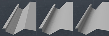
The preceding screenshot shows how the merge distance setting can affect the mesh. From left to right, as the distance value increases, the welding pairs of points become farther from each other. Normally, the default value works well, but in case you have troubles with the tool skipping some areas, you can try to fix it by increasing the threshold, thus forcing problematic areas to be welded.
Manipulating the edges of a model is always a very powerful way to work. From this tab, you will find many useful tools that will make your life easier.
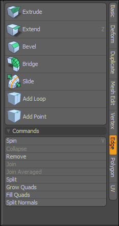
The ones I like the most are as follows:
Extend: Select an edge and click on this tool. Now, using the on-screen controls, you can control a newly generated polygon born from the selected edge. It is very useful if you want to grow your mesh from basic to complex shapes.

Bevel: Select an edge (or a group of edges) and make them round with this tool. You can control the roundness of the beveling with the tool's properties to give it more or less definition. This is extremely handy if you want to add details to your model or generate new geometry in a existing mesh.

Bridge: This generates a polygon connecting two edges. You select the two edges (or a group of edges), click on the tool, and they will be bridged. You can also control how the bridge works, if you want it segmented.

Slide: Select one or more edges and move them with this tool without the need to adjust the shape of the mesh. The mesh will be dynamically updated while you drag the edges. This is a great tool for making fine adjustments to your model.

Add loop/Loop slice: These two tools are used to add geometry based on an edge or a group of edges. You click on Add Loop and then click on an edge on the visor. It will add a cut generating the geometry. Another way is using the loop slice tool, which is more flexible and versatile to my taste. You can find the tool in the upper menu by navigating to Geometry | Slice | Loop.

Remove: The best way to get rid of one or more edges is just by using the Remove button. Select the edge you want to remove and click on the tool. The edge will disappear, but preserving the mesh involved. It's different than selecting the edge and hitting the backspace key, since this last method is destructive (it removes not only the edge, but all the geometry that edge was forming part of) while the remove method is non-destructive.

You will be using this tab most of the time. It equals—if not overcomes—the Edge tab in terms of usefulness:
Once again, we will not look at the full range of tools here, but we will focus on the most useful tools and the tools you will find most useful when you first start modeling:
Bevel: Similar to beveling an edge, you can bevel a polygon. The Bevel tool creates a new polygon, making an inset (scaling down the polygon to its own center) of the original one combined with a shift (extruding it along its face orientation). Both inset and shift can be positive or negative depending on whether the inset/shift is applied to the outside or the inside of the polygon. It is very useful for making things such as tips of poles, modeling frames, and making holes.

Smooth shift: This one is similar to the Bevel tool. The difference is that when dealing with curvy shapes, smooth shift seems to handle it better. My advice is that you use both tools and decide which one you like more. Personally, I prefer the simplicity of the Bevel tool, but again, it's your choice.

Bridge: This is the same exact thing as bridging edges, but applied to polygons.

Flip: In the 3D world, polygons aren't like a sheet of paper where you have a front face and a back face. Polygons are single-sided by default, so if you look at a polygon from behind, it will become invisible. The property that defines which face is visible is called normal. It basically states the direction the polygon is looking, leaving its back invisible. This tool actually flips the normal of the selected polygon.

Use this tool to make a polygon face one side or the other. This might sound silly, but it's useful when you are modeling and you find the geometry is being generated for some reason facing the wrong direction. Another good use is when you model a room and you use the Flip tool to make the floor, cellar, and walls face inside. So, when you see the model from the outside, the walls are invisible, but they get visible if you place the camera inside making it possible to have the walls not blocking the camera view.
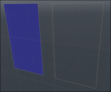
In the previous screenshot, each polygon is facing a different direction. So, we must say its normals are opposite. The left polygon is facing the camera while the right polygon is facing the opposite direction.
Set Material: This is an essential tool, of course, when you want to assign a material to some selected polygons. You will be using it all the time in its corresponding phase (materials and texturing).

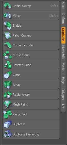
When dealing with modeling operations involving copying a mesh—or part of it—we will use the tools from the Duplicate tab:
The Duplicate tab is where you find the tools for everything related to making copies of the geometry or even the entire model. There are several tools here, and they are all more or less a bit advanced. Following the approach of the book, we will look at the main duplicate operations we will be using to get started with modeling. Let's check them out:
Mirror: This is classic mirror operation. This means that you will duplicate the selected object or geometry selection according to the tool's properties. A common operation is to make a symmetry, for example, modeling only one side of a face, then mirroring it to generate the other side.

Clone: This is a very handy tool to create copies of an object easily. With it, you can generate a number of copies without the need of making a manual copy/paste operation several times, thus saving you time. You can, for example, model an entire fence just by creating a single stake and making a bunch of copies in a single click. You can also use an offset value to modify the clones so that each one will be moved by the previous amount plus the offset.

Array: This is something like an advanced clone tool. It follows the same principles as cloning but you get more control. In addition to cloning an object, you can set the axes you want to clone through, apply an offset, and so on. Imagine yourself modeling a restaurant hall. Of course you will not be modeling each table and every set of chairs. You will not even clone it a number of times. You will want to use the Array tool, modeling one single set and then cloning it in an array of, let's say, 5 x 5 elements and you're done.

Radial Array: The same goes for the Radial Array tool, the only difference is that you don't work with the axis to establish the cloning, but with an angle number that defines how much degrees of a full 360º turn will cover the cloning. If you want to model the spokes of a bike, this is your tool.
The Mesh Edit tab is an all-purpose tab for modifying your model. It contains various interesting tools that you can use—and you will use—very often, regardless of being in vertex, edge, or polygon mode:
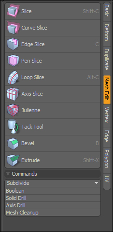
Most of my work is based around these tools. Let me show you the most used tools you will find here:
Edge Slice: This tool lets us draw cuts throughout the mesh as if we were using a cutting knife. You can go placing points anywhere on the surface of the mesh and they will connect themselves, creating more geometry.

Pen Slice: This one is a variation of the Edge Slice tool. You must be working in one of the orthographic views (top, right, left, and so on) and it will let you draw freely without having to take edges, polygons, or vertices. Once the slices are done, you can switch to a perspective view to find that your slices are in fact projected to the geometry of the mesh.

Loop Slice: Maybe the tool I use most. With this tool, you can add a slice to an entire loop in a single click. What makes this tool so powerful is that you can use it on edges or polygons or change the behavior of it if you want to change how the slices are created. We will discuss this later in more depth.

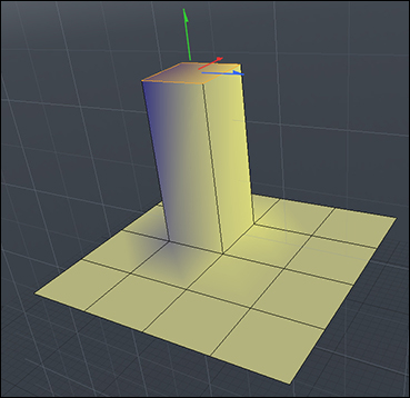
Extrude: The extrude tool is a timeless classic in every 3D software. An extrusion is when you create a new polygon from an existing one by shifting the new geometry out along a defined vector. Imagine a skyscraper rising from the underground.

The following figure shows a clear example of what an extrusion is:
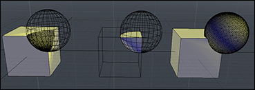
Boolean: The Boolean tool is a very classic operation too. This tool lets you merge two different objects, forming a single mesh. The intersecting geometry is removed and a new joining geometry is created. This option has got many settings, mainly affecting its behavior, so you can make a subtraction Boolean, Intersect Boolean, adding Boolean, and so on.

In the following figure, you can see examples of the main three Boolean operations. From left to right, they are as follows: Subtract , Intersect, and Add:
To perform a Boolean operation, you need two objects, each one in a separate layer. Select the object you want to be affected from the items list. Activate the tool and choose the Boolean mode you want for it. When you click on OK, the action will be performed and you will get the corresponding result.